EP1043045A2 - Installation d'extinction d'incendie - Google Patents
Installation d'extinction d'incendie Download PDFInfo
- Publication number
- EP1043045A2 EP1043045A2 EP00106176A EP00106176A EP1043045A2 EP 1043045 A2 EP1043045 A2 EP 1043045A2 EP 00106176 A EP00106176 A EP 00106176A EP 00106176 A EP00106176 A EP 00106176A EP 1043045 A2 EP1043045 A2 EP 1043045A2
- Authority
- EP
- European Patent Office
- Prior art keywords
- line
- gas
- container
- extinguishing
- extinguishing agent
- Prior art date
- Legal status (The legal status is an assumption and is not a legal conclusion. Google has not performed a legal analysis and makes no representation as to the accuracy of the status listed.)
- Granted
Links
- 238000009413 insulation Methods 0.000 claims abstract description 12
- 239000003795 chemical substances by application Substances 0.000 claims description 45
- 238000009826 distribution Methods 0.000 claims description 23
- 239000012071 phase Substances 0.000 claims description 19
- CURLTUGMZLYLDI-UHFFFAOYSA-N Carbon dioxide Chemical compound O=C=O CURLTUGMZLYLDI-UHFFFAOYSA-N 0.000 claims description 18
- 238000000034 method Methods 0.000 claims description 18
- 239000007788 liquid Substances 0.000 claims description 16
- 238000001816 cooling Methods 0.000 claims description 12
- 239000007791 liquid phase Substances 0.000 claims description 10
- 229910002092 carbon dioxide Inorganic materials 0.000 claims description 8
- 239000001569 carbon dioxide Substances 0.000 claims description 8
- 238000007654 immersion Methods 0.000 claims description 5
- 230000005855 radiation Effects 0.000 claims description 4
- 229910052799 carbon Inorganic materials 0.000 claims description 2
- 238000000605 extraction Methods 0.000 claims description 2
- 230000000630 rising effect Effects 0.000 claims 1
- 239000007789 gas Substances 0.000 description 44
- 230000000694 effects Effects 0.000 description 4
- 239000011521 glass Substances 0.000 description 4
- 238000003860 storage Methods 0.000 description 4
- 238000004519 manufacturing process Methods 0.000 description 3
- QVGXLLKOCUKJST-UHFFFAOYSA-N atomic oxygen Chemical compound [O] QVGXLLKOCUKJST-UHFFFAOYSA-N 0.000 description 2
- 238000012423 maintenance Methods 0.000 description 2
- 229910052760 oxygen Inorganic materials 0.000 description 2
- 239000001301 oxygen Substances 0.000 description 2
- 230000001960 triggered effect Effects 0.000 description 2
- XAGFODPZIPBFFR-UHFFFAOYSA-N aluminium Chemical compound [Al] XAGFODPZIPBFFR-UHFFFAOYSA-N 0.000 description 1
- 229910052782 aluminium Inorganic materials 0.000 description 1
- 230000001174 ascending effect Effects 0.000 description 1
- 238000007664 blowing Methods 0.000 description 1
- 238000006243 chemical reaction Methods 0.000 description 1
- 238000002485 combustion reaction Methods 0.000 description 1
- 238000011109 contamination Methods 0.000 description 1
- 230000003111 delayed effect Effects 0.000 description 1
- 238000012217 deletion Methods 0.000 description 1
- 230000037430 deletion Effects 0.000 description 1
- 238000013461 design Methods 0.000 description 1
- 238000001514 detection method Methods 0.000 description 1
- 230000005284 excitation Effects 0.000 description 1
- 239000000615 nonconductor Substances 0.000 description 1
- 230000009965 odorless effect Effects 0.000 description 1
- 239000003973 paint Substances 0.000 description 1
- 238000003825 pressing Methods 0.000 description 1
- 238000012545 processing Methods 0.000 description 1
- 238000010791 quenching Methods 0.000 description 1
- 230000000171 quenching effect Effects 0.000 description 1
- 238000005096 rolling process Methods 0.000 description 1
- 238000005070 sampling Methods 0.000 description 1
Images
Classifications
-
- A—HUMAN NECESSITIES
- A62—LIFE-SAVING; FIRE-FIGHTING
- A62C—FIRE-FIGHTING
- A62C99/00—Subject matter not provided for in other groups of this subclass
- A62C99/0009—Methods of extinguishing or preventing the spread of fire by cooling down or suffocating the flames
- A62C99/0018—Methods of extinguishing or preventing the spread of fire by cooling down or suffocating the flames using gases or vapours that do not support combustion, e.g. steam, carbon dioxide
Definitions
- the invention relates to a method for operating a fire extinguishing system with cryogenic carbon dioxide (CO 2 ) as an extinguishing agent, in particular a low-pressure CO 2 system (approx. 20 bar), in which the CO 2 is in the liquid phase at a temperature of -18 ° C to 22 ° C, in particular -20 ° c stored in an insulated container and kept at this temperature by means of a cooling unit and from there via a distributor line with a range valve to an extinguishing line with extinguishing nozzles, as well as a fire extinguishing system working according to the method.
- CO 2 cryogenic carbon dioxide
- Such fire extinguishing systems are so-called Kotika plants (Ko hlenklad ti ef ka lt).
- CO 2 is an odorless and colorless gas, an electrical non-conductor and is neither corrosive, polluting nor corrosive.
- By blowing carbon dioxide into a room the oxygen content of the room atmosphere can be reduced.
- the fire reaction is smothered by displacing the atmospheric oxygen.
- KOTIKA systems are suitable for Fighting fires in paint production and processing, food manufacturing, in switchgear, Data centers, rolling mills or similar
- the extinguishing system can have any suitable and recognized fire detection and extinguishing system control are triggered. So can for example with a pneumatic-electric or with the KOTIKA system with a pneumatic excitation system Glass barrel exciter and additionally via a manual trigger can be controlled. The glass barrel in a glass barrel stimulator bursts when it reaches its trigger temperature, or through Pressing the manual release relieves the control line and thus delivers a pneumatic control signal.
- CO 2 gas from the gas cushion of the KOTIKA system serves as the control medium.
- the KOTIKA container stands on a scale that checks the contents of the container. If carbon dioxide is lost, a contact is triggered to indicate a loss.
- the CO 2 storage temperature of approx. -20 ° C is maintained by the cooling unit and the insulation of the container. This keeps the pressure of the charged liquid carbonic acid at approx. 20 bar. With this technique, carbonic acid can be stored efficiently in large quantities. Such systems are economical from a CO 2 storage volume of 2000 kg.
- a KOTIKA container can supply several extinguishing areas via area valves.
- Carbon dioxide has a life-threatening effect in an extinguishing concentration, so special precautions for personal protection must be provided for room concentrations greater than 5% Vol CO 2 .
- a gas phase forms in the upper area of the extinguishing agent container and in the distribution line.
- the amount of gas from the distribution line must be routed through the lines to the extinguishing nozzles.
- a CO 2 gas is first discharged from the extinguishing nozzles. This gas cannot be extinguished.
- the extinguishable liquid gas is only applied to the source of the fire from the extinguishing nozzles after the gas phase has been completely discharged.
- the CO 2 gas phase flows through the pipe network to the extinguishing nozzles over a time factor of approx. 10 s.
- This time factor must be shortened, especially for property protection, when using CO 2 low-pressure fire extinguishing systems.
- this is essential for the object to be protected in the sense of quick and effective fire extinguishing. Due to the fire-specific influencing factors and the associated possible damage, shorter gas phases for a successful fire extinguishing must be realized.
- the invention has for its object the erasable Liquid gas phase faster through the extinguishing nozzles to the source of the fire to apply.
- the time factor for the gas phase should be ⁇ 5 s.
- This object is achieved in that the extinguishing agent drawn off from the liquid phase of the container is protected against cold radiation within the distributor line from the container to the area valve, and thus the extinguishing agent is kept liquid in the distributor line, and in that the CO 2 which forms in the distributor line rises upwards -Gas drawn off there and returned to the gas phase of the container.
- extinguishable liquid CO 2 is present in the area of the area valve, so that and in the event of fire, an extinguishable agent is immediately applied to the source of the fire via the extinguishing nozzles.
- This method can be used particularly advantageously if the extinguishing agent container is at the same height or higher than the area valve.
- a part of the liquid becomes from the liquid phase of the container Extinguished extinguishing agent and into the lower one Distribution line routed and protected against cold radiation, then it will be avoided with certainty that the Fills the distribution line with gas.
- liquid extinguishing agent is forced into circulation by means of a CO 2 pump.
- the forced circulation of the liquid CO 2 ensures at all times that no gas phase forms in the distribution line. However, if a gas phase forms, it can be subtracted.
- the requirement for the extinguishing effectiveness of the system to start is ⁇ 5 s.
- CO 2 is conveyed by means of two or more CO 2 pumps which are connected in parallel and can be shut off separately. This creates absolute operational security. With this measure, maintenance or servicing can be carried out on one of the two pumps during operation. In addition, if one pump fails, operation with one pump can be maintained.
- Another measure according to the invention is seen in the fact that the fire extinguishing system is operated in a constant pressure system with gas compensation and the recirculated CO 2 gas is additionally cooled.
- a classic low-pressure CO 2 system is hereby equipped with a gas compensation system and separate cooling unit for liquid storage up to the area valve.
- the gas compensation system with the return to the extinguishing agent container also prevents the gas phase in the distribution line.
- the two cooling units can be controlled via a cascade connection, with both cooling units being controlled in normal operation by means of a pressostat. In a classic low-pressure CO 2 system, this enables the entire extinguishing system to be operated independently. This procedure can be used particularly advantageously if the extinguishing agent container is higher than the area valve.
- cryogenic carbon dioxide (CO 2 ) as an extinguishing agent, which is stored in an insulated container connected to a cooling unit, from which a distribution line provided with an immersion pipe, a shut-off valve and an area valve leads to an extinguishing line with extinguishing nozzles, and the Container with a filling line for the extinguishing agent and a return gas line is proposed according to the invention for performing the method that the distribution line from the extinguishing agent container to the area valve is provided with insulation and a gas return line is connected to the highest point of the distribution line, the the other end is led into the gas phase of the extinguishing agent container.
- CO 2 cryogenic carbon dioxide
- a particularly advantageous device is seen in that a pocket tube from the liquid phase of the extinguishing agent container guided and connected to a bypass line, the free end led into the distribution line and with a Insulation is provided. At the highest point the Distribution line a gas return line with shut-off valve connected and with one in the gas phase of the Extinguishing agent container guided extraction tube to be connected.
- the invention proposes that in the Gas return line a heat exchanger is installed.
- One (or more) CO 2 gas pump is installed in the bypass line for forced circulation.
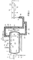
- Cryogenic carbon dioxide (CO 2 ) is stored as an extinguishing agent in an extinguishing agent container 1 with insulation 2.
- a temperature of the extinguishing agent of approximately -20 ° C. is maintained by a cooling unit 3 with a connecting line 4 to the extinguishing agent container 1.
- a vertical immersion tube 6 is let into the extinguishing agent container 1, to which a distributor line 5 provided with insulation 21 with a shut-off valve 7 is connected.
- the other end of the distributor line 5 is connected to an extinguishing line 8 with extinguishing nozzles 10 and is provided with an area valve 9.
- the valves 7 and 9 can also be isolated.
- the extinguishing agent is filled into the extinguishing agent container 1 via a filling line 11 with a filling valve 12. Furthermore, a gas return line 13 with a shut-off valve 14 is provided. 16 with a safety valve in a safety line 15 is designated. A control gas line, not shown, is led to an alarm valve of a mechanical delay device with an extinguishing valve.
- the quenching line 8 is assigned a pickup line 19 with a pickup 20, for example a glass bottle pickup, which is led to a manual release (not shown) and to the control line 37 with a control center (not shown).
- a horizontal dip tube 6a is provided on that the distribution line 5 is connected.
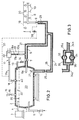
- the embodiment is the gas return line in two Split lines 17a and 17b, between which a Heat exchanger 32 is installed. Between the range valve 9 and the sub-line 17a is provided with a control line 37, in which a control valve 38 is installed. It is also between the heat exchanger 32 and the distribution line 5 another Return line 39 is provided. Forms in the partial line 17b a gas cushion 28a.
- the bypass line is divided into two sub-lines 24a and 24b, between which two pump lines 35 and 36 running parallel to one another are provided, in each of which a CO 2 pump 33 and 34 is installed.
- the pump lines 35, 36 and the pumps 33, 34 are surrounded by insulation 26 and are connected to the distributor line 5 in front of the area valve 9.
- the prerequisite here is that the range valve 9 is lower lies as the extinguishing agent container 1.
- the lockable Bypass line 24 connects the extinguishing agent container 1 and the Distribution line 5 to the area valve 9.
- the bypass line 24 prevents the entire distribution line 5 fills with gas and therefore a delayed deletion is initiated.
- a low-pressure CO 2 extinguishing system is equipped with a gas compensation system by means of a separate heat exchanger 32 for liquid storage.
- the ascending gas phase 28a is returned with the heat exchanger 32 and returned to the distributor line 5 by means of the return line 39.
- An equal pressure system is created via the partial line 17a and thus it is ensured that the boundary layers 30 and 30a are always at the same level.
- the distribution line is completely filled with a liquid CO 2 extinguishing agent.
- the process variants 1 to 3 can easily can be combined with each other or individually.
Landscapes
- Health & Medical Sciences (AREA)
- Public Health (AREA)
- Business, Economics & Management (AREA)
- Emergency Management (AREA)
- Fire-Extinguishing By Fire Departments, And Fire-Extinguishing Equipment And Control Thereof (AREA)
- Filling Or Discharging Of Gas Storage Vessels (AREA)
- Fire Alarms (AREA)
- Cereal-Derived Products (AREA)
Applications Claiming Priority (2)
| Application Number | Priority Date | Filing Date | Title |
|---|---|---|---|
| DE19915801A DE19915801A1 (de) | 1999-04-08 | 1999-04-08 | Feuerlöschanlage |
| DE19915801 | 1999-04-08 |
Publications (3)
| Publication Number | Publication Date |
|---|---|
| EP1043045A2 true EP1043045A2 (fr) | 2000-10-11 |
| EP1043045A3 EP1043045A3 (fr) | 2001-08-08 |
| EP1043045B1 EP1043045B1 (fr) | 2004-12-15 |
Family
ID=7903856
Family Applications (1)
| Application Number | Title | Priority Date | Filing Date |
|---|---|---|---|
| EP00106176A Expired - Lifetime EP1043045B1 (fr) | 1999-04-08 | 2000-03-21 | Installation d'extinction d'incendie |
Country Status (3)
| Country | Link |
|---|---|
| EP (1) | EP1043045B1 (fr) |
| AT (1) | ATE284735T1 (fr) |
| DE (2) | DE19915801A1 (fr) |
Cited By (1)
| Publication number | Priority date | Publication date | Assignee | Title |
|---|---|---|---|---|
| CN102451535A (zh) * | 2010-10-25 | 2012-05-16 | 薛玉良 | 一种大型灭火装置 |
Families Citing this family (1)
| Publication number | Priority date | Publication date | Assignee | Title |
|---|---|---|---|---|
| CN106955439A (zh) * | 2017-04-06 | 2017-07-18 | 南京信息职业技术学院 | 一种智能配电箱用主动喷射式二氧化碳灭火装置 |
Family Cites Families (2)
| Publication number | Priority date | Publication date | Assignee | Title |
|---|---|---|---|---|
| DE1708100C3 (de) * | 1967-02-24 | 1976-01-08 | Total Foerstner & Co, 6802 Ladenburg | Verfahren zum Ausspülen des Leitungssystems einer Niederdruckkohlensäure-Feuerlöschvorrichtung nach einem LöschVorgang |
| US5850876A (en) * | 1990-01-08 | 1998-12-22 | Pyrozone Pty. Ltd. | Apparatus and system for the storage and supply of liquid CO2 at low pressure for extinguishing of fires |
-
1999
- 1999-04-08 DE DE19915801A patent/DE19915801A1/de not_active Withdrawn
-
2000
- 2000-03-21 DE DE50008930T patent/DE50008930D1/de not_active Expired - Fee Related
- 2000-03-21 EP EP00106176A patent/EP1043045B1/fr not_active Expired - Lifetime
- 2000-03-21 AT AT00106176T patent/ATE284735T1/de not_active IP Right Cessation
Cited By (1)
| Publication number | Priority date | Publication date | Assignee | Title |
|---|---|---|---|---|
| CN102451535A (zh) * | 2010-10-25 | 2012-05-16 | 薛玉良 | 一种大型灭火装置 |
Also Published As
| Publication number | Publication date |
|---|---|
| ATE284735T1 (de) | 2005-01-15 |
| DE19915801A1 (de) | 2000-10-12 |
| EP1043045A3 (fr) | 2001-08-08 |
| DE50008930D1 (de) | 2005-01-20 |
| EP1043045B1 (fr) | 2004-12-15 |
Similar Documents
| Publication | Publication Date | Title |
|---|---|---|
| EP1062005B1 (fr) | Procede d'inertisation pour la prevention et l'extinction des incendies dans des locaux fermes | |
| EP2459922B1 (fr) | Système de gaz combustible, en particulier pour des bateaux de commerce | |
| DE102017008210B4 (de) | Vorrichtung und Verfahren zum Befüllen eines mobilen Kältemitteltanks mit einem kryogenen Kältemittel | |
| EP3081842A1 (fr) | Procede et dispositif de remplissage d'un reservoir mobile avec du dioxyde de carbone liquide | |
| EP0769190B1 (fr) | Procede et dispositif de generation de gaz inerte | |
| EP0496066A1 (fr) | Dispositif de lutte contre les incendies avec un reservoir de fluide cryogénique | |
| DE69937279T2 (de) | Kontrolliertes Entlüftungssystem für ultrahochreines Zufuhrsystem für verflüssigte Druckgase | |
| EP1043045B1 (fr) | Installation d'extinction d'incendie | |
| EP0859649B1 (fr) | Dispositif d'extinction et ensemble soupape pour ledit dispositif | |
| DE1086255B (de) | Verfahren und Vorrichtung zur Rueckkondensation von Gasen | |
| DE19830458C1 (de) | Verfahren und Vorrichtung zum Trocknen von bei der Erdölförderung anfallenden Erdgasen | |
| DE2747492A1 (de) | Sicherheitseinsatz fuer gefaesse zum aufbewahren tiefsiedender verfluessigter gase | |
| EP1142611B1 (fr) | Procédé pour l'optimisation d'un système d'extinction d'incendie à pulvérisation d'eau et système d'extinction d'incendie à pulvérisation d'eau pour la mise en oeuvre du procédé | |
| DE3828136A1 (de) | Verfahren und vorrichtung zur kuehlung eines mit fluessigkeit gefuellten behaelters | |
| DE4215131C2 (de) | Anlage zur sicheren Entsorgung von in einem Druckgasbehälter gespeicherten Gefahrgasen | |
| DE4432344C2 (de) | Verfahren und Vorrichtung zum Inertisieren von Reaktoren | |
| DE966655C (de) | Verfahren zur Regelung des Dampfdruckes in Fluessiggas-Behaeltern | |
| DE4445656C1 (de) | Speicherung von Acetylen | |
| EP3450819B1 (fr) | Procédé de remplissage d'un réservoir d'agent de refroidissement mobile d'un agent de refroidissement cryogénique | |
| EP0011126B1 (fr) | Procédé pour la protection des installations de production et de traitement de l'oxyde d'éthylène contre la décomposition de l'oxyde d'éthylène et dispositif pour la production et le traitement del'oxyde d'éthylène protégé contre la décomposition de l'oxyde d'éthylène | |
| DE2456207C2 (de) | Feuerloeschanlage | |
| DE3011300A1 (de) | Verfahren und vorrichtung zum ableiten von bei stoerfaellen aus einem lagerbhaelter austrtenden gasen | |
| DE809424C (de) | Sicherheitseinrichtung fuer Anlagen, die mit Acetylen unter Bedingungen arbeiten, bei denen ein fortschreitender Zerfall des Acetylens moeglich ist | |
| DE640047C (de) | Reaktionsturm zur Durchfuehrung chemischer und physikalischer Reaktionen zwischen Gasen, Daempfen oder dampfhaltigen Gasen und Fluessigkeiten | |
| DE895701C (de) | Verfahren und Vorrichtung zur Verwendung von Kohlensaeure als Feuerloeschmittel |
Legal Events
| Date | Code | Title | Description |
|---|---|---|---|
| PUAI | Public reference made under article 153(3) epc to a published international application that has entered the european phase |
Free format text: ORIGINAL CODE: 0009012 |
|
| AK | Designated contracting states |
Kind code of ref document: A2 Designated state(s): AT BE DE FI LU NL |
|
| AX | Request for extension of the european patent |
Free format text: AL;LT;LV;MK;RO;SI |
|
| PUAL | Search report despatched |
Free format text: ORIGINAL CODE: 0009013 |
|
| AK | Designated contracting states |
Kind code of ref document: A3 Designated state(s): AT BE CH CY DE DK ES FI FR GB GR IE IT LI LU MC NL PT SE |
|
| AX | Request for extension of the european patent |
Free format text: AL;LT;LV;MK;RO;SI |
|
| 17P | Request for examination filed |
Effective date: 20010712 |
|
| AKX | Designation fees paid |
Free format text: AT BE DE FI LU NL |
|
| GRAP | Despatch of communication of intention to grant a patent |
Free format text: ORIGINAL CODE: EPIDOSNIGR1 |
|
| GRAS | Grant fee paid |
Free format text: ORIGINAL CODE: EPIDOSNIGR3 |
|
| GRAA | (expected) grant |
Free format text: ORIGINAL CODE: 0009210 |
|
| AK | Designated contracting states |
Kind code of ref document: B1 Designated state(s): AT BE DE FI LU NL |
|
| PG25 | Lapsed in a contracting state [announced via postgrant information from national office to epo] |
Ref country code: NL Free format text: LAPSE BECAUSE OF FAILURE TO SUBMIT A TRANSLATION OF THE DESCRIPTION OR TO PAY THE FEE WITHIN THE PRESCRIBED TIME-LIMIT Effective date: 20041215 Ref country code: FI Free format text: LAPSE BECAUSE OF FAILURE TO SUBMIT A TRANSLATION OF THE DESCRIPTION OR TO PAY THE FEE WITHIN THE PRESCRIBED TIME-LIMIT Effective date: 20041215 |
|
| REF | Corresponds to: |
Ref document number: 50008930 Country of ref document: DE Date of ref document: 20050120 Kind code of ref document: P |
|
| PG25 | Lapsed in a contracting state [announced via postgrant information from national office to epo] |
Ref country code: AT Free format text: LAPSE BECAUSE OF NON-PAYMENT OF DUE FEES Effective date: 20050321 |
|
| PGFP | Annual fee paid to national office [announced via postgrant information from national office to epo] |
Ref country code: BE Payment date: 20050322 Year of fee payment: 6 |
|
| PGFP | Annual fee paid to national office [announced via postgrant information from national office to epo] |
Ref country code: LU Payment date: 20050325 Year of fee payment: 6 |
|
| PGFP | Annual fee paid to national office [announced via postgrant information from national office to epo] |
Ref country code: DE Payment date: 20050425 Year of fee payment: 6 |
|
| NLV1 | Nl: lapsed or annulled due to failure to fulfill the requirements of art. 29p and 29m of the patents act | ||
| PLBE | No opposition filed within time limit |
Free format text: ORIGINAL CODE: 0009261 |
|
| STAA | Information on the status of an ep patent application or granted ep patent |
Free format text: STATUS: NO OPPOSITION FILED WITHIN TIME LIMIT |
|
| 26N | No opposition filed |
Effective date: 20050916 |
|
| PG25 | Lapsed in a contracting state [announced via postgrant information from national office to epo] |
Ref country code: LU Free format text: LAPSE BECAUSE OF NON-PAYMENT OF DUE FEES Effective date: 20060331 Ref country code: BE Free format text: LAPSE BECAUSE OF NON-PAYMENT OF DUE FEES Effective date: 20060331 |
|
| PG25 | Lapsed in a contracting state [announced via postgrant information from national office to epo] |
Ref country code: DE Free format text: LAPSE BECAUSE OF NON-PAYMENT OF DUE FEES Effective date: 20061003 |
|
| BERE | Be: lapsed |
Owner name: *TOTAL WALTHER G.M.B.H. FEUERSCHUTZ UND SICHERHEIT Effective date: 20060331 |