EP1043113B1 - Verfahren zum Abdachen und Entgräten der Zähne eines Zahnrads, Vorrichtung zum Durchführen des Verfahrens, und zugehörendes Werkzeug - Google Patents
Verfahren zum Abdachen und Entgräten der Zähne eines Zahnrads, Vorrichtung zum Durchführen des Verfahrens, und zugehörendes Werkzeug Download PDFInfo
- Publication number
- EP1043113B1 EP1043113B1 EP00107582A EP00107582A EP1043113B1 EP 1043113 B1 EP1043113 B1 EP 1043113B1 EP 00107582 A EP00107582 A EP 00107582A EP 00107582 A EP00107582 A EP 00107582A EP 1043113 B1 EP1043113 B1 EP 1043113B1
- Authority
- EP
- European Patent Office
- Prior art keywords
- teeth
- tool
- tooth
- gear
- permanent deformation
- Prior art date
- Legal status (The legal status is an assumption and is not a legal conclusion. Google has not performed a legal analysis and makes no representation as to the accuracy of the status listed.)
- Expired - Lifetime
Links
- 238000000034 method Methods 0.000 title claims description 18
- 230000000295 complement effect Effects 0.000 claims description 3
- 230000000694 effects Effects 0.000 claims 4
- 230000006835 compression Effects 0.000 claims 1
- 238000007906 compression Methods 0.000 claims 1
- 238000005520 cutting process Methods 0.000 description 3
- 230000001154 acute effect Effects 0.000 description 2
- 230000015572 biosynthetic process Effects 0.000 description 2
- 238000010438 heat treatment Methods 0.000 description 1
- 238000003780 insertion Methods 0.000 description 1
- 230000037431 insertion Effects 0.000 description 1
- 238000003754 machining Methods 0.000 description 1
- 238000004519 manufacturing process Methods 0.000 description 1
- 230000002093 peripheral effect Effects 0.000 description 1
- 238000003860 storage Methods 0.000 description 1
Images

Classifications
-
- B—PERFORMING OPERATIONS; TRANSPORTING
- B21—MECHANICAL METAL-WORKING WITHOUT ESSENTIALLY REMOVING MATERIAL; PUNCHING METAL
- B21H—MAKING PARTICULAR METAL OBJECTS BY ROLLING, e.g. SCREWS, WHEELS, RINGS, BARRELS, BALLS
- B21H5/00—Making gear wheels, racks, spline shafts or worms
- B21H5/02—Making gear wheels, racks, spline shafts or worms with cylindrical outline, e.g. by means of die rolls
- B21H5/022—Finishing gear teeth with cylindrical outline, e.g. burnishing
-
- Y—GENERAL TAGGING OF NEW TECHNOLOGICAL DEVELOPMENTS; GENERAL TAGGING OF CROSS-SECTIONAL TECHNOLOGIES SPANNING OVER SEVERAL SECTIONS OF THE IPC; TECHNICAL SUBJECTS COVERED BY FORMER USPC CROSS-REFERENCE ART COLLECTIONS [XRACs] AND DIGESTS
- Y10—TECHNICAL SUBJECTS COVERED BY FORMER USPC
- Y10T—TECHNICAL SUBJECTS COVERED BY FORMER US CLASSIFICATION
- Y10T29/00—Metal working
- Y10T29/49—Method of mechanical manufacture
- Y10T29/49462—Gear making
- Y10T29/49467—Gear shaping
-
- Y—GENERAL TAGGING OF NEW TECHNOLOGICAL DEVELOPMENTS; GENERAL TAGGING OF CROSS-SECTIONAL TECHNOLOGIES SPANNING OVER SEVERAL SECTIONS OF THE IPC; TECHNICAL SUBJECTS COVERED BY FORMER USPC CROSS-REFERENCE ART COLLECTIONS [XRACs] AND DIGESTS
- Y10—TECHNICAL SUBJECTS COVERED BY FORMER USPC
- Y10T—TECHNICAL SUBJECTS COVERED BY FORMER US CLASSIFICATION
- Y10T29/00—Metal working
- Y10T29/49—Method of mechanical manufacture
- Y10T29/49462—Gear making
- Y10T29/49467—Gear shaping
- Y10T29/49471—Roll forming
-
- Y—GENERAL TAGGING OF NEW TECHNOLOGICAL DEVELOPMENTS; GENERAL TAGGING OF CROSS-SECTIONAL TECHNOLOGIES SPANNING OVER SEVERAL SECTIONS OF THE IPC; TECHNICAL SUBJECTS COVERED BY FORMER USPC CROSS-REFERENCE ART COLLECTIONS [XRACs] AND DIGESTS
- Y10—TECHNICAL SUBJECTS COVERED BY FORMER USPC
- Y10T—TECHNICAL SUBJECTS COVERED BY FORMER US CLASSIFICATION
- Y10T29/00—Metal working
- Y10T29/49—Method of mechanical manufacture
- Y10T29/49462—Gear making
- Y10T29/49467—Gear shaping
- Y10T29/49476—Gear tooth cutting
-
- Y—GENERAL TAGGING OF NEW TECHNOLOGICAL DEVELOPMENTS; GENERAL TAGGING OF CROSS-SECTIONAL TECHNOLOGIES SPANNING OVER SEVERAL SECTIONS OF THE IPC; TECHNICAL SUBJECTS COVERED BY FORMER USPC CROSS-REFERENCE ART COLLECTIONS [XRACs] AND DIGESTS
- Y10—TECHNICAL SUBJECTS COVERED BY FORMER USPC
- Y10T—TECHNICAL SUBJECTS COVERED BY FORMER US CLASSIFICATION
- Y10T407/00—Cutters, for shaping
- Y10T407/17—Gear cutting tool
- Y10T407/174—Gear generating, revolving shaper cutting tool
-
- Y—GENERAL TAGGING OF NEW TECHNOLOGICAL DEVELOPMENTS; GENERAL TAGGING OF CROSS-SECTIONAL TECHNOLOGIES SPANNING OVER SEVERAL SECTIONS OF THE IPC; TECHNICAL SUBJECTS COVERED BY FORMER USPC CROSS-REFERENCE ART COLLECTIONS [XRACs] AND DIGESTS
- Y10—TECHNICAL SUBJECTS COVERED BY FORMER USPC
- Y10T—TECHNICAL SUBJECTS COVERED BY FORMER US CLASSIFICATION
- Y10T409/00—Gear cutting, milling, or planing
- Y10T409/10—Gear cutting
- Y10T409/101113—Gear chamfering or deburring
Definitions
- the present invention relates to a method of chamfering and deburring gear teeth. Further, it relates to a tool and a device for performing said method.
- the present invention relates to a method of chamfering and deburring helical gears, to which the following description refers purely by way of example.
- a method according to the preamble of claim 1 is known, for example, from DE-U-83 07 877.
- Gears normally comprise teeth defined by respective sides and end faces, which, with the sides, form sharp edges along which burrs are left after chip-forming machining, and which must therefore be chamfered for the gear to work and mesh properly.
- One known deburring and chamfering method employs a tool featuring a ring gear comprising a number of teeth, which are brought into contact with and pressed against the sharp edges to deform them permanently and form bevels between the sides and end faces of the gear teeth.
- a major drawback of the above known method lies in the formation of curls projecting from the gear teeth and partly inside the gaps between the teeth, and which are formed by the permanently deformed material of the tooth, and seriously impair operation of the gear, particularly in the case of high-precision gears.
- the problem is further compounded in the case of gears which are ground after heat treatment, in which case, the hardened curls may indent the grinding tool.
- the present invention also relates to a chamfering and deburring tool (see claim 4).
- the present invention also relates to a chamfering and deburring device (see claim 12).
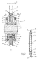
- Number 1 in Figure 1 indicates as a whole a device for chamfering and deburring the teeth of a gear 2 shown by the dash lines in Figure 1.
- Device 1 comprises a hub 3 and an axis 4 of rotation and symmetry.
- Hub 3 is fitted to a known shaft (not shown) and comprises a ring 5 integral with hub 3 and extending radially; an L-section ring 6 fitted to ring 5 by screws 7 (only one shown in Figure 1); and two annular disks 8 and 9 fitted to ring 5 by screws 10 (only one shown in Figure 1).
- Rings 5 and 6 define an annular seat 11 housing two tools 12 and 13, which are in the form of annular disks facing and parallel to each other, are fitted to respective rings 5 and 6 by means of screws 14, and are located a given axial distance apart.
- Disk 8 is located on the opposite side of rings 5 and 6 to disk 9.
- Disks 8 and 9 are positioned facing and parallel to each other, and define a seat 15 housing two annular deburring disks 16 and 17 facing and parallel to each other and adjacent to respective tools 12 and 13.
- Disks 16 and 17 rest on respective rings 5 and 6, and are pushed towards each other by springs 18 located between disks 8, 9 and respective disks 16, 17.
- Disks 16 and 17 comprise screws 19 fitted to disks 16 and 17 and in turn comprising respective heads 20 projecting axially with respect to disks 16 and 17 and housed inside respective seats 21 formed in disks 8 and 9.
- Device 1 also comprises two disks 22 located between deburring disks 16, 17 and respective tools 12, 13. That is, whereas tools 12 and 13 are fitted rigidly to hub 3, deburring disks 16 and 17 are allowed to slide axially by a limited amount with respect to hub 3.
- Deburring disks 16 and 17 have respective outer peripheral edges 23 bent towards each other at the outer peripheries of respective tools 12 and 13, and having cutting edges for deburring the sides of gear 2.
- Gear 2 is connected to device 1 and mounted for rotation about a respective axis 24 parallel to axis 4.
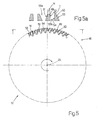
- tool 12 comprises an axis 25 coincident, in use, with axis 4 of device 1; an annular disk 26 having a central hole 27; and a ring gear 28 integral with disk 26.
- Annular disk 26 has a number of threaded holes 29 equally spaced about axis 25 and which are engaged, in use, by screws 14 ( Figure 1).
- ring gear 28 comprises at least one portion 30 having teeth 31; and at least one portion 32 having teeth 33. Portions 30 and 32 are complementary to each other and may, for example, each occupy half of ring gear 28.
- each tooth 31 comprises sides 34 and 35 forming an acute angle A ranging between 0° and 90°.
- each tooth 33 comprises sides 36 and 37 forming an acute angle B considerably smaller than angle A and ranging between 0° and 15°.
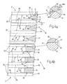
- gear 2 comprises a succession of helical teeth 38, each of which has a respective axis 39 inclined at an angle C with respect to a direction parallel to axis 24.
- Each tooth 38 comprises two sides 40 and 41 parallel to axis 39; and two end faces 42 parallel to each other and perpendicular to axis 24 of gear 2.
- gear 2 is aligned with tools 12 and 13, with axis 24 parallel to axis 4 of device 1, so as to mesh with tools 12 and 13; a known device (not shown) applies pressure between gear 2 and device 1 in direction 44 to push tools 12 and 13 against gear 2; deburring disks 16 and 17 push respective edges 23 into contact with the sides of gear; and springs 18 press edges 23 against the sides of gear 2.
- portion 30 of ring gear 28 of tool 12 engages gear 2 on one side of gear 2, with teeth 31 located successively between respective teeth 38 of gear 2. More specifically, side 35 of each tooth 31 is positioned contacting an edge between side 41 and respective end face 42 of one tooth 38, while side 34 of tooth 31 is positioned contacting an edge between side 40 and the respective end face of an adjacent tooth 38. Gradual forced insertion of teeth 31 between teeth 38 of gear 2 and the pressure exerted in direction 44 between gear 2 and device 1 produce considerable pressure between faces 34 and 35 of each tooth 31 and the edges of two successive, adjacent teeth 38, so as to permanently deform the edges as shown in the enlarged detail of Figure 4a.
- Permanent deformation of the edges is such as to flatten the edges and form respective chamfer faces 45 between respective sides 40 and 41 and respective end faces 42, and to also form a curl 46a on the side of tooth 38, and a curl 46b on face 42 ( Figure 4a).
- each tooth 31 forms, by permanent deformation, chamfer faces 45 on sides 40 and 41 of two adjacent teeth 38 of gear 2.
- Chamfer faces 45 are inclined, with respect to respective sides 40 and 41, at an angle D, which is a complement of 180° with the inclination E of faces 34 and 35 with respect to the axes 39 of teeth 38.
- Tests have shown gears 2 to operate best with an inclination E ranging between 5° and 45°.
- portion 32 of ring gear 28 of tool 12 engages one side of gear 2, with teeth 33 located successively between respective teeth 38 of gear 2. More specifically, side 37 of each tooth 33 is positioned contacting curl 46a between side 41 and respective chamfer face 45, while side 36 of tooth 33 is positioned contacting curl 46a between side 40 and respective chamfer face 45 of an adjacent tooth 38. Like teeth 31, the pressure exerted in direction 44 produces considerable pressure between faces 36 and 37 and curls 46a, so as to deform curls 46a as shown in the enlarged detail of Figure 4b.
- Deformation of curls 46a is a permanent deformation by which curls 46a are flattened and "ironed out” so to speak on to sides 41, while curls 46b projecting from end faces 42 of tooth 38 are removed by cutting edges 23 of deburring disks 16, 17.
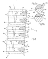
- tool 12 comprises a ring gear 48 in turn comprising teeth 49 and teeth 50 equally spaced and alternating with each other about ring gear 48.
- Each tooth 49 comprises a side 51 inclined at a given angle with respect to a direction parallel to axis 25, and a side 52 inclined with respect to axis 25 at a smaller angle than side 51; and sides 51 and 52 of each tooth 49 form an angle H comparable to angle B in the Figure 3 embodiment.
- Each tooth 50 comprises a side 53 inclined at a given angle with respect to axis 25, and a side 54 inclined with respect to axis 25 at a given angle considerably smaller than that of side 53; and sides 53 and 54 of each tooth 50 form an angle I comparable to angle A in the Figure 3 embodiment.
- Teeth 49 and 50 are so arranged that side 51 of each tooth 49 faces side 53 of the adjacent tooth 50 on one side, and side 52 faces side 54 of the adjacent tooth 50 on the opposite side, and so that flared gaps 55a of a given size between sides 51 and 53 of adjacent teeth 49 and 50 alternate about ring gear 48 with flared gaps 55b formed between sides 52 and 54 of respective teeth 49 and 50 and considerably smaller than gaps 55a.
- ring gear 48 of tool 12 engages gear 2 on one side, with teeth 49 and 50 located successively between respective teeth 38 of gear 2. More specifically, sides 51, 52 and 53, 54 of respective teeth 49 and 50 are brought into contact with the edges between sides 40 and 41 and end faces 42 of gear 2. In particular, the edge between side 41 and end face 42 of each tooth 38 contacts side 53; and, as in the Figure 3 embodiment, side 53 of tooth 50 forms, by permanent deformation, chamfer face 45 between side 41 and face 42.
- each side 41 is brought into contact with a respective side 52 of a tooth 49, which provides for further permanent deformation by exerting pressure on curl 46a.
- each side 40 is brought into contact with a respective side 54 of a respective tooth 50, which provides for further permanent deformation by exerting pressure on curl 46a.
- the outer curl 46b is removed by cutting edges 23 of disks 16, 17.
Landscapes
- Engineering & Computer Science (AREA)
- Mechanical Engineering (AREA)
- Gear Processing (AREA)
Claims (13)
- Verfahren zum Abfasen und Entgraten der Zähne eines Zahnrads (2), das erste Zähne (38) umfasst, wobei die ersten Zähne (38) jeweils eine erste und eine zweite Seite (40, 41) und jeweilige Endflächen (42) umfassen, und wobei das Verfahren folgende Schritte umfasst: In Eingriffbringen des Zahnrads (2) mit zumindest einem Werkzeug (12, 13), wobei das Werkzeug (12, 13) einen Zahnring (28; 48) umfasst, der in die ersten Zähne (38) an Kanten eingreift, die zwiechen den ersten und zweiten Seiten (40, 41) und den Endflächen (42) ausgebildet sind; Ausüben von Druck zwischen den ersten Zähnen (38) und dem Zahnring (28; 48); und Bewirken, einer ersten permanenten Verformung der ersten Zähne (38) zwischen jeweils den ersten und zweiten Seiten (40, 41) und den Endflächen (42); wobei das Verfahren gekennzeichnet ist durch das Umfassen des weiteren Schritts des Bewirkens einer zweiten permanenten Verformung der ersten Zähne (38) zwischen jeweils den ersten und zweiten Seiten (40, 41) und den Endflächen (42); wobei die erste und zweite Verformung mittels Blockwerkzeugen (12, 13) bewirkt wird, die jeweils eine erste Anzahl von Zähnen (31, 49) und eine zweite Anzahl von Zähnen (33; 50) zum jeweiligen Bewirken der ersten permanenten Verformung und der zweiten permanenten Verformung aufweisen.
- Verfahren nach Anspruch 1, dadurch gekennzeichnet, dass jeder Zahn der ersten Anzahl von Zähnen (31) gleichzeitig zwei Fasen (45) von zwei benachbarten ersten Zähnen (38) des Zahnrads (2) bildet und jeder Zahn der zweiten Anzahl von Zähnen (33) das Ebnen einer Wölbung (46a) von zwei benachbarten ersten Zähnen (38) des Zahnrads (2) vorsieht.
- Verfahren nach Anspruch 1, dadurch gekennzeichnet, dass jeder Zahn der ersten Anzahl von Zähnen (49) und jeder Zahn der zweiten Anzahl von Zähnen (50) einerseits eine Fase ausbilden und andererseits das Ebnen der Wölbung (46a) von zwei benachbarten ersten Zähnen (38) vorsehen.
- Werkzeug zum Umsetzen des Verfahrens nach Anspruch 1 bis 3, dadurch gekennzeichnet, dass der Zahnring (28; 48), der en bloc und einstückig mit einer ringförmigen Scheibe (26) ausgebildet ist, eine erste Anzahl von Zähnen (31; 49) und eine zweite Anzahl von Zähnen (33, 50) zum jeweiligen Bewirken der ersten und zweiten permanenten Verformung umfasst.
- Werkzeug nach Anspruch 4, dadurch gekennzeichnet, dass der Zahnring (28) zumindest einen ersten und zumindest einen zweiten Abschnitt (30, 32) umfasst; der zumindest eine erste und der zumindest eine zweite Abschnitt (30, 32) sich gegenseitig ergänzen; der zumindest eine erste Abschnitt (30) die erste Anzahl von Zähnen (31) umfasst; und der zumindest eine zweite Abschnitt (30) die zweite Anzahl von Zähnen (33) umfasst.
- Werkzeug nach Anspruch 5, dadurch gekennzeichnet, dass bei der ersten Anzahl von Zähnen (31) jeder Zahn jeweilige Seiten (34, 35) aufweist, die einen ersten Winkel (A) bilden; und bei der zweiten Anzahl von Zähnen (33) jeder Zahn jeweilige Seiten (35, 36) aufweist, die einen zweiten Winkel (B) bilden; wobei der zweite Winkel (B) erheblich kleiner als der erste Winkel (A) ist.
- Werkzeug nach Anspruch 6, dadurch gekennzeichnet, dass der zweite Winkel (B) zwischen 0° und 15° liegt.
- Werkzeug nach Anspruch 6, dadurch gekennzeichnet, dass der erste Winkel (A) zwischen 0° und 90° liegt.
- Werkzeug nach Anspruch 4, dadurch gekennzeichnet, dass bei der ersten Anzahl von Zähnen (31) jeder Zahn in zwei benachbarte erste Zähne (38) des Zahnrads (2) eingreift, um die erste permanente Verformung zu bewirken; bei der zweiten Anzahl von Zähnen (33) jeder Zahn in zwei benachbarte erste Zähne (38) eingreift, um die zweite permanente Verformung zu bewirken.
- Werkzeug nach Anspruch 4, dadurch gekennzeichnet, dass sich die erste Anzahl von Zähnen (49) mit der zweiten Anzahl von Zähnen (50) auf den Zahnring (48) abwechseln.
- Werkzeug nach Anspruch 10, dadurch gekennzeichnet, dass bei der ersten Anzahl von Zähnen (49) jeder Zahn jeweilige Seiten (51, 52) umfasst und bei der zweiten Anzahl von Zähnen (50) jeder Zahn jeweilige Seiten (53, 54) umfasst; die Seiten (51, 53) zum Bewirken der ersten permanenten Verformung verwendet werden; und die Seiten (52, 54) zum Bewirken der zweiten permanenten Verformung verwendet werden.
- Gerät zum Umsetzen des Verfahrens nach Anspruch 1 bis 3, dadurch gekennzeichnet, dass es zumindest ein Werkzeug (12, 13) nach Anspruch 4 bis 11 umfasst; sich das zumindest eine Werkzeug (12, 13) um eine Achse (4) dreht.
- Gerät nach Anspruch 12, dadurch gekennzeichnet, dass es zumindest eine Entgratscheibe (16, 17) umfasst, die sich um die Achse (4) dreht.
Applications Claiming Priority (2)
| Application Number | Priority Date | Filing Date | Title |
|---|---|---|---|
| IT1999BO000164A IT1309965B1 (it) | 1999-04-09 | 1999-04-09 | Metodo si smussatura e sbavatura di denti di ruote dentate,dispositivo per l'attuazione di tale metodo e relativo utensile |
| ITBO990164 | 1999-04-09 |
Publications (2)
| Publication Number | Publication Date |
|---|---|
| EP1043113A1 EP1043113A1 (de) | 2000-10-11 |
| EP1043113B1 true EP1043113B1 (de) | 2003-07-02 |
Family
ID=11343893
Family Applications (1)
| Application Number | Title | Priority Date | Filing Date |
|---|---|---|---|
| EP00107582A Expired - Lifetime EP1043113B1 (de) | 1999-04-09 | 2000-04-07 | Verfahren zum Abdachen und Entgräten der Zähne eines Zahnrads, Vorrichtung zum Durchführen des Verfahrens, und zugehörendes Werkzeug |
Country Status (7)
| Country | Link |
|---|---|
| US (1) | US6571475B1 (de) |
| EP (1) | EP1043113B1 (de) |
| AR (1) | AR023412A1 (de) |
| AT (1) | ATE244101T1 (de) |
| BR (1) | BR0002244A (de) |
| DE (1) | DE60003601T2 (de) |
| IT (1) | IT1309965B1 (de) |
Families Citing this family (10)
| Publication number | Priority date | Publication date | Assignee | Title |
|---|---|---|---|---|
| DE10129853C1 (de) * | 2001-06-21 | 2003-01-09 | Gleason Works | Werkzeug zum Anfasen und Entgraten der stirnseitigen Zahnkanten von Zahnrädern |
| DE10340468A1 (de) * | 2003-09-03 | 2005-04-21 | Werner Hermann Wera Werke | Entgratvorrichtung mit Entgratscheibe |
| CN100412734C (zh) * | 2006-09-29 | 2008-08-20 | 天津第一机床总厂 | 一种弧齿锥齿轮倒棱控制方法 |
| US20100050325A1 (en) * | 2008-09-01 | 2010-03-04 | Tzu-Feng Wang-Lee | Structure For adjusting inside Circumference of Helmet |
| JP5302638B2 (ja) * | 2008-11-18 | 2013-10-02 | 本田技研工業株式会社 | 歯車加工装置及びフレージングカッタ |
| DE102009018392A1 (de) * | 2009-04-22 | 2010-10-28 | The Gleason Works | Anordnung zur Verbindung eines Werkzeugrads und einer Werkzeugaufnahme |
| CN102059597B (zh) * | 2010-03-12 | 2013-05-29 | 内蒙古第一机械制造(集团)有限公司 | 一种硬齿面插齿刀负倒棱的加工方法 |
| DE102011006993B4 (de) * | 2011-04-07 | 2025-10-09 | MODUL MT Verzahntechnik GmbH | Verfahren zur Herstellung von Verzahnungen an Werkstücken |
| DE102013218542B4 (de) * | 2013-09-16 | 2015-09-24 | Felsomat Gmbh & Co Kg | Verfahren zum Anfasen und Glätten von verzahnten Werkstücken und zugehörige Bearbeitungsstation |
| DE102024104116A1 (de) * | 2024-02-14 | 2025-08-14 | Gleason-Pfauter Maschinenfabrik Gmbh | Verfahren zum Anfasen einer Zahnkante einer Werkstückverzahnung |
Family Cites Families (7)
| Publication number | Priority date | Publication date | Assignee | Title |
|---|---|---|---|---|
| CH539484A (de) * | 1970-05-12 | 1973-07-31 | Zahnradfabrik Friedrichshafen | Einrichtung zum Einwalzen von Stirnkanten von vorverzahnten Zahnrädern |
| US3735619A (en) * | 1972-01-27 | 1973-05-29 | Lear Siegler Inc | Gear roll chamfering |
| FR2225244B1 (de) * | 1973-04-14 | 1978-01-06 | Hurth Masch Zahnrad Carl | |
| IT1206410B (it) * | 1977-05-03 | 1989-04-21 | Samputensili Spa | Perfezionamento negli utensili per smussare e sbavare gli ingranaggi |
| DE8307877U1 (de) * | 1983-03-17 | 1984-04-05 | Carl Hurth Maschinen- und Zahnradfabrik GmbH & Co, 8000 München | Vorrichtung zum spanenden oder spanlosen Entgraten oder Brechen der stirnseitigen Zahnkanten von grad- oder schrägverzahnten Zahnrädern |
| DE4130927C2 (de) * | 1991-09-18 | 1997-06-19 | Praewema Werkzeugmaschinenfabr | Werkzeugzahnrad zum Entgraten bzw. Anfasen der Stirnkanten der Zähne eines schrägverzahnten Werkstückzahnrades |
| DE29715092U1 (de) * | 1997-08-22 | 1997-10-23 | The Gleason Works, Rochester, N.Y. | Vorrichtung zum Anfassen und Entgraten der stirnseitigen Zahnkanten von Zahnrädern |
-
1999
- 1999-04-09 IT IT1999BO000164A patent/IT1309965B1/it active
-
2000
- 2000-04-07 DE DE60003601T patent/DE60003601T2/de not_active Expired - Lifetime
- 2000-04-07 US US09/544,859 patent/US6571475B1/en not_active Expired - Lifetime
- 2000-04-07 AT AT00107582T patent/ATE244101T1/de not_active IP Right Cessation
- 2000-04-07 AR ARP000101599A patent/AR023412A1/es unknown
- 2000-04-07 EP EP00107582A patent/EP1043113B1/de not_active Expired - Lifetime
- 2000-04-10 BR BR0002244-6A patent/BR0002244A/pt not_active Application Discontinuation
Also Published As
| Publication number | Publication date |
|---|---|
| BR0002244A (pt) | 2001-10-09 |
| US6571475B1 (en) | 2003-06-03 |
| ITBO990164A1 (it) | 2000-10-09 |
| DE60003601D1 (de) | 2003-08-07 |
| IT1309965B1 (it) | 2002-02-05 |
| DE60003601T2 (de) | 2004-06-03 |
| ATE244101T1 (de) | 2003-07-15 |
| EP1043113A1 (de) | 2000-10-11 |
| AR023412A1 (es) | 2002-09-04 |
| ITBO990164A0 (it) | 1999-04-09 |
Similar Documents
| Publication | Publication Date | Title |
|---|---|---|
| KR101496436B1 (ko) | 단부절삭 공작물 휠의 2차 버를 제거하기 위한 방법 및 장치 | |
| US6571475B1 (en) | Method of chamfering and deburring gear teeth, device implementing such a method, and relative tool | |
| JP2790376B2 (ja) | 薄鋼板からの歯車の冷間成形 | |
| US5154553A (en) | Apparatus for chamfering and deburring the end edges of a toothed production gear | |
| WO2004085093A1 (ja) | ボルトの製造方法および製造装置並びにこれに用いる螺子転造ダイス並びに多重螺子ボルト | |
| US7076875B2 (en) | Method of manufacturing compound helical planet gears having different leads | |
| EP0921897B1 (de) | Verfahren zur herstellung von zahnrädern und dazu hergestelltes produkt | |
| JPS6258847B2 (de) | ||
| JP3484321B2 (ja) | 自動車用トランスミッションにおけるトルク伝達部材,スプライン歯形の成形方法およびスプライン歯形成形装置 | |
| KR100237124B1 (ko) | 기어의 전조 방법 및 장치 | |
| JPH0146216B2 (de) | ||
| CN108138937B (zh) | 具有内齿部和冠状齿部的齿圈及其制造方法和带有这种齿圈的变速箱 | |
| JPH0988988A (ja) | シャフトの外周面にボールスプライン溝を形成する方法 | |
| JP4077482B2 (ja) | 螺旋体の転造加工方法とその転造用ダイス | |
| JP2005061494A (ja) | 無段変速機のバリエータ部品の製造方法及び無段変速機のバリエータ部品 | |
| EP0691164A1 (de) | Verfahren zur herstellung einer antriebsplatte | |
| JP3700156B2 (ja) | ヘリカルギヤとデファレンシャル装置 | |
| CN204639348U (zh) | 一种剃齿工装夹具的防削渣结构 | |
| SU1162557A1 (ru) | Трубчата плашка | |
| US20130199044A1 (en) | Method of Forming a Sprocket | |
| KR200256631Y1 (ko) | 니플 자동 성형기 | |
| SU837516A1 (ru) | Инструмент дл пластического де-фОРМиРОВАНи РАбОчиХ пОВЕРХНОСТЕйзубчАТОй дЕТАли | |
| US3995352A (en) | Gear shaving cutter | |
| SU632509A1 (ru) | Инструмент дл чистовой обработки закаленных зубчатых колес | |
| JP2001054820A (ja) | 一体型ホブカッタ |
Legal Events
| Date | Code | Title | Description |
|---|---|---|---|
| PUAI | Public reference made under article 153(3) epc to a published international application that has entered the european phase |
Free format text: ORIGINAL CODE: 0009012 |
|
| AK | Designated contracting states |
Kind code of ref document: A1 Designated state(s): AT BE CH CY DE DK ES FI FR GB GR IE IT LI LU MC NL PT SE |
|
| AX | Request for extension of the european patent |
Free format text: AL;LT;LV;MK;RO;SI |
|
| 17P | Request for examination filed |
Effective date: 20010321 |
|
| AKX | Designation fees paid |
Free format text: AT BE CH CY DE DK ES FI FR GB GR IE IT LI LU MC NL PT SE |
|
| GRAH | Despatch of communication of intention to grant a patent |
Free format text: ORIGINAL CODE: EPIDOS IGRA |
|
| GRAH | Despatch of communication of intention to grant a patent |
Free format text: ORIGINAL CODE: EPIDOS IGRA |
|
| GRAA | (expected) grant |
Free format text: ORIGINAL CODE: 0009210 |
|
| AK | Designated contracting states |
Designated state(s): AT BE CH CY DE DK ES FI FR GB GR IE IT LI LU MC NL PT SE |
|
| PG25 | Lapsed in a contracting state [announced via postgrant information from national office to epo] |
Ref country code: NL Free format text: LAPSE BECAUSE OF FAILURE TO SUBMIT A TRANSLATION OF THE DESCRIPTION OR TO PAY THE FEE WITHIN THE PRESCRIBED TIME-LIMIT Effective date: 20030702 Ref country code: CH Free format text: LAPSE BECAUSE OF FAILURE TO SUBMIT A TRANSLATION OF THE DESCRIPTION OR TO PAY THE FEE WITHIN THE PRESCRIBED TIME-LIMIT Effective date: 20030702 Ref country code: CY Free format text: LAPSE BECAUSE OF FAILURE TO SUBMIT A TRANSLATION OF THE DESCRIPTION OR TO PAY THE FEE WITHIN THE PRESCRIBED TIME-LIMIT Effective date: 20030702 Ref country code: FI Free format text: LAPSE BECAUSE OF FAILURE TO SUBMIT A TRANSLATION OF THE DESCRIPTION OR TO PAY THE FEE WITHIN THE PRESCRIBED TIME-LIMIT Effective date: 20030702 Ref country code: LI Free format text: LAPSE BECAUSE OF FAILURE TO SUBMIT A TRANSLATION OF THE DESCRIPTION OR TO PAY THE FEE WITHIN THE PRESCRIBED TIME-LIMIT Effective date: 20030702 Ref country code: AT Free format text: LAPSE BECAUSE OF FAILURE TO SUBMIT A TRANSLATION OF THE DESCRIPTION OR TO PAY THE FEE WITHIN THE PRESCRIBED TIME-LIMIT Effective date: 20030702 |
|
| REG | Reference to a national code |
Ref country code: GB Ref legal event code: FG4D |
|
| REG | Reference to a national code |
Ref country code: CH Ref legal event code: EP |
|
| REG | Reference to a national code |
Ref country code: IE Ref legal event code: FG4D |
|
| REF | Corresponds to: |
Ref document number: 60003601 Country of ref document: DE Date of ref document: 20030807 Kind code of ref document: P |
|
| PG25 | Lapsed in a contracting state [announced via postgrant information from national office to epo] |
Ref country code: GR Free format text: LAPSE BECAUSE OF FAILURE TO SUBMIT A TRANSLATION OF THE DESCRIPTION OR TO PAY THE FEE WITHIN THE PRESCRIBED TIME-LIMIT Effective date: 20031002 Ref country code: SE Free format text: LAPSE BECAUSE OF FAILURE TO SUBMIT A TRANSLATION OF THE DESCRIPTION OR TO PAY THE FEE WITHIN THE PRESCRIBED TIME-LIMIT Effective date: 20031002 Ref country code: PT Free format text: LAPSE BECAUSE OF FAILURE TO SUBMIT A TRANSLATION OF THE DESCRIPTION OR TO PAY THE FEE WITHIN THE PRESCRIBED TIME-LIMIT Effective date: 20031002 Ref country code: DK Free format text: LAPSE BECAUSE OF FAILURE TO SUBMIT A TRANSLATION OF THE DESCRIPTION OR TO PAY THE FEE WITHIN THE PRESCRIBED TIME-LIMIT Effective date: 20031002 |
|
| PG25 | Lapsed in a contracting state [announced via postgrant information from national office to epo] |
Ref country code: ES Free format text: LAPSE BECAUSE OF FAILURE TO SUBMIT A TRANSLATION OF THE DESCRIPTION OR TO PAY THE FEE WITHIN THE PRESCRIBED TIME-LIMIT Effective date: 20031013 |
|
| NLV1 | Nl: lapsed or annulled due to failure to fulfill the requirements of art. 29p and 29m of the patents act | ||
| REG | Reference to a national code |
Ref country code: CH Ref legal event code: PL |
|
| PG25 | Lapsed in a contracting state [announced via postgrant information from national office to epo] |
Ref country code: LU Free format text: LAPSE BECAUSE OF NON-PAYMENT OF DUE FEES Effective date: 20040407 Ref country code: IE Free format text: LAPSE BECAUSE OF NON-PAYMENT OF DUE FEES Effective date: 20040407 |
|
| PG25 | Lapsed in a contracting state [announced via postgrant information from national office to epo] |
Ref country code: MC Free format text: LAPSE BECAUSE OF NON-PAYMENT OF DUE FEES Effective date: 20040430 |
|
| ET | Fr: translation filed | ||
| PLBE | No opposition filed within time limit |
Free format text: ORIGINAL CODE: 0009261 |
|
| STAA | Information on the status of an ep patent application or granted ep patent |
Free format text: STATUS: NO OPPOSITION FILED WITHIN TIME LIMIT |
|
| 26N | No opposition filed |
Effective date: 20040405 |
|
| REG | Reference to a national code |
Ref country code: IE Ref legal event code: MM4A |
|
| REG | Reference to a national code |
Ref country code: FR Ref legal event code: PLFP Year of fee payment: 17 |
|
| REG | Reference to a national code |
Ref country code: FR Ref legal event code: PLFP Year of fee payment: 18 |
|
| REG | Reference to a national code |
Ref country code: FR Ref legal event code: PLFP Year of fee payment: 19 |
|
| PGFP | Annual fee paid to national office [announced via postgrant information from national office to epo] |
Ref country code: IT Payment date: 20190411 Year of fee payment: 20 Ref country code: DE Payment date: 20190531 Year of fee payment: 20 |
|
| PGFP | Annual fee paid to national office [announced via postgrant information from national office to epo] |
Ref country code: BE Payment date: 20190425 Year of fee payment: 20 Ref country code: FR Payment date: 20190426 Year of fee payment: 20 |
|
| PGFP | Annual fee paid to national office [announced via postgrant information from national office to epo] |
Ref country code: GB Payment date: 20190429 Year of fee payment: 20 |
|
| REG | Reference to a national code |
Ref country code: DE Ref legal event code: R071 Ref document number: 60003601 Country of ref document: DE |
|
| REG | Reference to a national code |
Ref country code: GB Ref legal event code: PE20 Expiry date: 20200406 |
|
| REG | Reference to a national code |
Ref country code: BE Ref legal event code: MK Effective date: 20200407 |
|
| PG25 | Lapsed in a contracting state [announced via postgrant information from national office to epo] |
Ref country code: GB Free format text: LAPSE BECAUSE OF EXPIRATION OF PROTECTION Effective date: 20200406 |