EP1043248A2 - Chaíne transporteuse denté pouvant suivre des courbes, et elément de chaíne - Google Patents
Chaíne transporteuse denté pouvant suivre des courbes, et elément de chaíne Download PDFInfo
- Publication number
- EP1043248A2 EP1043248A2 EP00104985A EP00104985A EP1043248A2 EP 1043248 A2 EP1043248 A2 EP 1043248A2 EP 00104985 A EP00104985 A EP 00104985A EP 00104985 A EP00104985 A EP 00104985A EP 1043248 A2 EP1043248 A2 EP 1043248A2
- Authority
- EP
- European Patent Office
- Prior art keywords
- plate
- conveyor
- plates
- slot
- slots
- Prior art date
- Legal status (The legal status is an assumption and is not a legal conclusion. Google has not performed a legal analysis and makes no representation as to the accuracy of the status listed.)
- Withdrawn
Links
Images


Classifications
-
- B—PERFORMING OPERATIONS; TRANSPORTING
- B65—CONVEYING; PACKING; STORING; HANDLING THIN OR FILAMENTARY MATERIAL
- B65G—TRANSPORT OR STORAGE DEVICES, e.g. CONVEYORS FOR LOADING OR TIPPING, SHOP CONVEYOR SYSTEMS OR PNEUMATIC TUBE CONVEYORS
- B65G17/00—Conveyors having an endless traction element, e.g. a chain, transmitting movement to a continuous or substantially-continuous load-carrying surface or to a series of individual load-carriers; Endless-chain conveyors in which the chains form the load-carrying surface
- B65G17/06—Conveyors having an endless traction element, e.g. a chain, transmitting movement to a continuous or substantially-continuous load-carrying surface or to a series of individual load-carriers; Endless-chain conveyors in which the chains form the load-carrying surface having a load-carrying surface formed by a series of interconnected, e.g. longitudinal, links, plates, or platforms
- B65G17/08—Conveyors having an endless traction element, e.g. a chain, transmitting movement to a continuous or substantially-continuous load-carrying surface or to a series of individual load-carriers; Endless-chain conveyors in which the chains form the load-carrying surface having a load-carrying surface formed by a series of interconnected, e.g. longitudinal, links, plates, or platforms the surface being formed by the traction element
-
- B—PERFORMING OPERATIONS; TRANSPORTING
- B65—CONVEYING; PACKING; STORING; HANDLING THIN OR FILAMENTARY MATERIAL
- B65G—TRANSPORT OR STORAGE DEVICES, e.g. CONVEYORS FOR LOADING OR TIPPING, SHOP CONVEYOR SYSTEMS OR PNEUMATIC TUBE CONVEYORS
- B65G17/00—Conveyors having an endless traction element, e.g. a chain, transmitting movement to a continuous or substantially-continuous load-carrying surface or to a series of individual load-carriers; Endless-chain conveyors in which the chains form the load-carrying surface
- B65G17/30—Details; Auxiliary devices
- B65G17/38—Chains or like traction elements; Connections between traction elements and load-carriers
-
- B—PERFORMING OPERATIONS; TRANSPORTING
- B65—CONVEYING; PACKING; STORING; HANDLING THIN OR FILAMENTARY MATERIAL
- B65G—TRANSPORT OR STORAGE DEVICES, e.g. CONVEYORS FOR LOADING OR TIPPING, SHOP CONVEYOR SYSTEMS OR PNEUMATIC TUBE CONVEYORS
- B65G2201/00—Indexing codes relating to handling devices, e.g. conveyors, characterised by the type of product or load being conveyed or handled
- B65G2201/02—Articles
Definitions
- the present invention refers to the field of toothed chains, in particular of toothed-chain conveyors, which comprise, on each chain pin, a number of co-operating links or plates set alongside each other so as to form a sort of moving belt.
- the said conveyors are generally actuated by meshing sprocket or gear wheels meshing therewith, said sprocket or gear wheels having a number of toothings set alongside each other.
- a known toothed-chain conveyor of this type is shown in the annexed Figs. 1 and 2.
- the links or plates of known toothed-chain conveyors are generally made like links or plates of gearing chains and, more preferably, like links of so-called "silent chains".
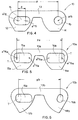
- a known type of plate is shown in the attached Figure 1.
- the plate 1 shown in Figure 1 has a two-lobed shape, the two lobes 2, 4 being joined by a bridge-like body 3, and each lobe having a particular profile designed to mesh with the gear wheels for transmitting motion with minimum noise emission.
- Each lobe has a slot, 5 and 6, respectively, for engagement by a pin or link stud 7.
- the shape of the slots and the cross sectional shape of the pin in the figures are shown as circular and of corresponding dimensions except for any clearance.
- Also widely used are link studs having vertically elongated cross sectional shape, which couple to slots with a number of centres, in order to enable rotation of the plates in an area corresponding to the gear wheels.
- the pitch between the link studs in known conveyors is generally approximately 1 ⁇ 2 in. (12.7 mm).
- the space occupied by a pin or link stud within the respective slot is such as not to enable any substantial sliding between the plate and the pin in the longitudinal direction, i.e., in the direction of travel of the conveyor. Consequently, known toothed-chain conveyors are suitable for conveying along a rectilinear path, but cannot be adapted to curved paths having a curvature in the plane of conveyance travel.
- toothed-chain conveyors are widely preferred in certain sectors, such as in glass-making, where they have to work at high temperatures and where the use of other types of conveyors is penalized by installation costs or by high running costs due to rapid wear.
- An aim of the present invention is to overcome the drawback referred to above and to provide a tooted-chain conveyor which may cover a path with curves of wide radius in the plane of the path, i.e., in the plane of useful travel of the conveyor.
- a plate element for a chain or chain conveyor, as claimed in Claim 6 is also part of the present invention.
- the new chain conveyor is able to cover paths with curves of wide radius in the plane of conveyance; it can be manufactured as a normal chain or as a silent chain.
- a chain plate according to the invention in Fig. 4, is designated by the reference number 10, and has two lobes 12, 14 which are connected by a central bridge-like body 13. Each one of the lobes has a slot for engagement of a pin or link stud, the slots being designated, respectively, by 15 and 16.
- the slot 16 has a traditional, circular shape, with axis a 16 .
- the slot 15 has a shape elongated in the longitudinal direction, where by longitudinal is meant the direction of advance, i.e. the travel direction, of the conveyor.
- the elongated shape of the slot 15 comprises two half-circumferences, with axes a' 15 and a'' 15 , which have their diameters equal to the diameter d 16 of the slot 16 and are at a distance d from one another, and an intermediate slot portion having parallel sides.
- the distance or pitch p between the distal axis a' 15 of the slot 15 and the axis a 16 is generally, but not exclusively, one inch (25.4 mm); i.e., the plate is generally longer than traditional plates.
- the profile of the lobes is generally made according to one of the per-se known shapes of silent-type chains or the like, and is not part of the present application.
- the plate according to the invention is designated as a whole by 10a, and comprises two lobes 12a, 14a and a central body 13a. Both of the lobes are provided with identical longitudinally elongated openings, referenced 15a, 16a, having a basically rectangular shape with rounded corners.
- the slots are suitable for being engaged by traditional link studs T of the type having a vertically elongated cross section, as illustrated by the dashed line in the figure. Each slot defines two spaced axes a' 15a , a'' 15a ; a' 16a , a'' 16a corresponding to a distal and a proximal positions of the link stud in the slot. Engagement between the link studs and the slots enables a rotation of the plate about the link stud to enable engagement with driving gear wheels and enables reciprocal longitudinal sliding.
- Fig. 6 shows a further plate 10b according to the invention, which is equipped with a longitudinally elongated slot 15b, on one lobe 12b, and with a traditional multicentric slot 16b, on the other lobe 14b.
- the multicentric slot has a per-se known shape known, which is designed to enable rotation of the plate on the link stud T having an elongated cross section.
- the proximal side and distal side of the elongated slot 15b have the shape of the two sides of a multicentric slot.
- a pitch p b between the distal centres of the slots is approximately 1 in., corresponding to 25.4 mm.
- the profiles of the lobes are preferably traditional profiles for chains of the so-called "silent" type.
- the invention may equally well apply to chains not belonging to this category.
- the plates described are mere examples of a wide range of possible plates, according to the invention, having one or two elongated slots, of various shapes.
- the invention also envisages various accessory elements of the conveyor.
- Fig. 7 illustrates a so-called “solid" plate, 20, with a straight bottom edge, as is sometimes used in a transversally intermediate or lateral position on the toothed-chain conveyor for guide engagement in appropriate grooves in the driving gear wheels.
- the plate 20 has one or two elongated slots like the other plates of the conveyor. In the particular embodiment shown in the drawing, the slots have semicircular ends and are designed for engaging with a round-sectioned link stud T.
- Fig. 8 is a cross sectional view of an embodiment of link stud 30 that may be used with the plates of Figs. 5 and 6.
- the link stud has a body with an oblong cross section, and is defined by two parallel sides and by two semicircular sides; it moreover has a quadrangular stub 31.
- An end washer 34 having a quadrangular opening 35 engages with the link stud.
- Fig. 10 shows a containment plate 40 for a conveyor according to the invention.
- the containment plates are designed to be mounted on the link studs laterally, or also in intermediate positions, so as to protrude onto a plane of conveyance defined by the plates, to act as containment means on the conveyed material.
- the containment plates have one or two elongated slots which correspond in terms of shape and size to the slots of the conveyor plates.
- the plate 40 has slots like the plate 10 in Fig. 4.
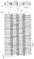
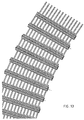
- Figs. 11, 12 and 13 show a chain conveyor 100 according to the present invention, made using plates 10c each provided with a slot 16c having a shape corresponding to the cross sectional shape of the link stud T, and with a longitudinally elongated slot 15c.
- the conveyor is shown in a condition in which it is moving along a rectilinear path, i.e., with the link studs T parallel to one another and with a pitch p c between them, i.e., with the plates arranged according to the maximum longitudinal extension.
- the link studs occupy the distal position of the longitudinally elongated slots of each plate.
Landscapes
- Engineering & Computer Science (AREA)
- Mechanical Engineering (AREA)
- Chain Conveyers (AREA)
- Attitude Control For Articles On Conveyors (AREA)
Applications Claiming Priority (2)
| Application Number | Priority Date | Filing Date | Title |
|---|---|---|---|
| ITMI990544 IT1311752B1 (it) | 1999-03-18 | 1999-03-18 | Trasportatore a catena a denti con possibilita' di movimentocurvilineo nel piano di scorrimento;ed elementi di catena |
| ITMI990544 | 1999-03-18 |
Publications (2)
| Publication Number | Publication Date |
|---|---|
| EP1043248A2 true EP1043248A2 (fr) | 2000-10-11 |
| EP1043248A3 EP1043248A3 (fr) | 2003-07-02 |
Family
ID=11382320
Family Applications (1)
| Application Number | Title | Priority Date | Filing Date |
|---|---|---|---|
| EP00104985A Withdrawn EP1043248A3 (fr) | 1999-03-18 | 2000-03-09 | Chaíne transporteuse denté pouvant suivre des courbes, et elément de chaíne |
Country Status (3)
| Country | Link |
|---|---|
| EP (1) | EP1043248A3 (fr) |
| CA (1) | CA2300795A1 (fr) |
| IT (1) | IT1311752B1 (fr) |
Cited By (7)
| Publication number | Priority date | Publication date | Assignee | Title |
|---|---|---|---|---|
| EP1241117A1 (fr) * | 2001-03-14 | 2002-09-18 | Pennine Industrial Equipment Limited | Membre d'obturation |
| WO2004067459A1 (fr) * | 2003-01-31 | 2004-08-12 | Bormioli Rocco & Figlio S.P.A. | Transporteur refractaire pour objets chauds |
| EP1956267A2 (fr) | 2007-02-12 | 2008-08-13 | Fond Metalli Conveyors S.r.l. | Chaîne silencieuse, particulièrement pour convoyeurs |
| EP2505522A1 (fr) * | 2011-03-30 | 2012-10-03 | Pennine Industrial Equipment Limited | Chaîne de convoyeur |
| DE102011111943A1 (de) * | 2011-08-30 | 2013-02-28 | Robert Bosch Gmbh | Transportzahnkette zum Transportieren von erwärmten Transportgütern |
| CN109573145A (zh) * | 2019-01-24 | 2019-04-05 | 四川金仕达自动化设备有限公司 | 一种转弯链式输蛋设备 |
| WO2024263418A1 (fr) * | 2023-06-21 | 2024-12-26 | Ramsey Products Corporation | Chaîne transporteuse à partie supérieure plate |
Family Cites Families (2)
| Publication number | Priority date | Publication date | Assignee | Title |
|---|---|---|---|---|
| US3646752A (en) * | 1970-09-28 | 1972-03-07 | Conveyor Specialties Co | Plastic encased metal ribbed flexible conveyor chain |
| DE4433557C1 (de) * | 1994-09-07 | 1995-12-21 | Mannesmann Ag | Transportzahnkette für Stückgut, insbesondere für Glasgut |
-
1999
- 1999-03-18 IT ITMI990544 patent/IT1311752B1/it active
-
2000
- 2000-03-09 EP EP00104985A patent/EP1043248A3/fr not_active Withdrawn
- 2000-03-15 CA CA 2300795 patent/CA2300795A1/fr not_active Abandoned
Cited By (8)
| Publication number | Priority date | Publication date | Assignee | Title |
|---|---|---|---|---|
| EP1241117A1 (fr) * | 2001-03-14 | 2002-09-18 | Pennine Industrial Equipment Limited | Membre d'obturation |
| WO2004067459A1 (fr) * | 2003-01-31 | 2004-08-12 | Bormioli Rocco & Figlio S.P.A. | Transporteur refractaire pour objets chauds |
| EP1956267A2 (fr) | 2007-02-12 | 2008-08-13 | Fond Metalli Conveyors S.r.l. | Chaîne silencieuse, particulièrement pour convoyeurs |
| EP2505522A1 (fr) * | 2011-03-30 | 2012-10-03 | Pennine Industrial Equipment Limited | Chaîne de convoyeur |
| DE102011111943A1 (de) * | 2011-08-30 | 2013-02-28 | Robert Bosch Gmbh | Transportzahnkette zum Transportieren von erwärmten Transportgütern |
| CN109573145A (zh) * | 2019-01-24 | 2019-04-05 | 四川金仕达自动化设备有限公司 | 一种转弯链式输蛋设备 |
| WO2024263418A1 (fr) * | 2023-06-21 | 2024-12-26 | Ramsey Products Corporation | Chaîne transporteuse à partie supérieure plate |
| US12358728B1 (en) * | 2023-06-21 | 2025-07-15 | Ramsey Products Corporation | Flat top conveyor chain |
Also Published As
| Publication number | Publication date |
|---|---|
| EP1043248A3 (fr) | 2003-07-02 |
| IT1311752B1 (it) | 2002-03-19 |
| CA2300795A1 (fr) | 2000-09-18 |
| ITMI990544A1 (it) | 2000-09-18 |
Similar Documents
| Publication | Publication Date | Title |
|---|---|---|
| EP0384076B1 (fr) | Chaîne à dents silencieuse | |
| US5437581A (en) | Phased chain assemblies | |
| US5419743A (en) | Low noise chain drive | |
| CA1062921A (fr) | Plaque de fermeture fixee a pression | |
| US7837028B2 (en) | Radius chain modular conveyor | |
| US6766899B1 (en) | Sprocket with combined hinge/center drive | |
| US6564933B2 (en) | Conveyor chain | |
| EP1149780B1 (fr) | Convoyeur à bande | |
| CA2007511C (fr) | Joint articule pour chaine | |
| US5397280A (en) | System phasing of overhead cam engine timing chains | |
| US5267909A (en) | Power transmission chain constructed with butt style links | |
| EP1043248A2 (fr) | Chaíne transporteuse denté pouvant suivre des courbes, et elément de chaíne | |
| EP1054825A1 (fr) | Dispositif de manutention | |
| US7267221B2 (en) | Silent modular conveyor and conveyor links | |
| US20020020612A1 (en) | Module with alternating, offset cross-rib | |
| US4909381A (en) | Shavings conveyor | |
| JPH1172144A (ja) | チェーン組立体およびチェーン・スプロケット組立体 | |
| US6159122A (en) | Silent chain | |
| US7137917B2 (en) | Transport tooth chain with reduced wear on the vertical dimension of its link members | |
| EP0750134B1 (fr) | Courroie à maillons | |
| KR20080091142A (ko) | 컨베이어 매트용 모듈, 모듈형 컨베이어 매트 및 컨베이어 | |
| EP0845425B1 (fr) | Module d'une bande transporteuse et bande transporteuse | |
| US20080070732A1 (en) | Gemini chain system with resonance elimination feature | |
| US3957153A (en) | Pusher-type chain for conveyor means | |
| EP0980843A3 (fr) | Dispositif de convoyage continu réversible |
Legal Events
| Date | Code | Title | Description |
|---|---|---|---|
| PUAI | Public reference made under article 153(3) epc to a published international application that has entered the european phase |
Free format text: ORIGINAL CODE: 0009012 |
|
| AK | Designated contracting states |
Kind code of ref document: A2 Designated state(s): AT BE CH CY DE DK ES FI FR GB GR IE IT LI LU MC NL PT SE |
|
| AX | Request for extension of the european patent |
Free format text: AL;LT;LV;MK;RO;SI |
|
| RIC1 | Information provided on ipc code assigned before grant |
Ipc: 7B 65G 17/08 B Ipc: 7B 65G 17/38 A |
|
| PUAL | Search report despatched |
Free format text: ORIGINAL CODE: 0009013 |
|
| AK | Designated contracting states |
Designated state(s): AT BE CH CY DE DK ES FI FR GB GR IE IT LI LU MC NL PT SE |
|
| AX | Request for extension of the european patent |
Extension state: AL LT LV MK RO SI |
|
| AKX | Designation fees paid | ||
| REG | Reference to a national code |
Ref country code: DE Ref legal event code: 8566 |
|
| STAA | Information on the status of an ep patent application or granted ep patent |
Free format text: STATUS: THE APPLICATION IS DEEMED TO BE WITHDRAWN |
|
| 18D | Application deemed to be withdrawn |
Effective date: 20040103 |