EP1043431B1 - Palier pour un rotor de filage dans un métier à filer à bout libre - Google Patents
Palier pour un rotor de filage dans un métier à filer à bout libre Download PDFInfo
- Publication number
- EP1043431B1 EP1043431B1 EP00103286A EP00103286A EP1043431B1 EP 1043431 B1 EP1043431 B1 EP 1043431B1 EP 00103286 A EP00103286 A EP 00103286A EP 00103286 A EP00103286 A EP 00103286A EP 1043431 B1 EP1043431 B1 EP 1043431B1
- Authority
- EP
- European Patent Office
- Prior art keywords
- bearing
- rotor
- arrangement according
- rotor shaft
- bearing arrangement
- Prior art date
- Legal status (The legal status is an assumption and is not a legal conclusion. Google has not performed a legal analysis and makes no representation as to the accuracy of the status listed.)
- Expired - Lifetime
Links
- 238000009987 spinning Methods 0.000 title claims description 32
- 230000005291 magnetic effect Effects 0.000 claims description 39
- 230000003068 static effect Effects 0.000 claims description 18
- 239000002344 surface layer Substances 0.000 claims description 15
- 239000000463 material Substances 0.000 claims description 14
- 230000005294 ferromagnetic effect Effects 0.000 claims description 9
- 238000007383 open-end spinning Methods 0.000 claims description 8
- 230000002829 reductive effect Effects 0.000 claims description 6
- 239000000696 magnetic material Substances 0.000 claims description 5
- 239000011248 coating agent Substances 0.000 claims description 4
- 238000000576 coating method Methods 0.000 claims description 4
- 229910052761 rare earth metal Inorganic materials 0.000 claims description 4
- 150000002910 rare earth metals Chemical class 0.000 claims description 4
- 229910000881 Cu alloy Inorganic materials 0.000 claims description 3
- 239000007770 graphite material Substances 0.000 claims description 3
- RYGMFSIKBFXOCR-UHFFFAOYSA-N Copper Chemical compound [Cu] RYGMFSIKBFXOCR-UHFFFAOYSA-N 0.000 claims description 2
- 229910052802 copper Inorganic materials 0.000 claims description 2
- 239000010949 copper Substances 0.000 claims description 2
- 239000000835 fiber Substances 0.000 claims description 2
- OKTJSMMVPCPJKN-UHFFFAOYSA-N Carbon Chemical compound [C] OKTJSMMVPCPJKN-UHFFFAOYSA-N 0.000 claims 1
- 229910052799 carbon Inorganic materials 0.000 claims 1
- 230000014759 maintenance of location Effects 0.000 claims 1
- 238000004140 cleaning Methods 0.000 description 7
- 230000008901 benefit Effects 0.000 description 5
- 230000004907 flux Effects 0.000 description 4
- 238000010438 heat treatment Methods 0.000 description 4
- 238000003860 storage Methods 0.000 description 4
- 230000015572 biosynthetic process Effects 0.000 description 3
- 230000000694 effects Effects 0.000 description 3
- 238000004519 manufacturing process Methods 0.000 description 3
- 229920000049 Carbon (fiber) Polymers 0.000 description 2
- PXHVJJICTQNCMI-UHFFFAOYSA-N Nickel Chemical compound [Ni] PXHVJJICTQNCMI-UHFFFAOYSA-N 0.000 description 2
- ATJFFYVFTNAWJD-UHFFFAOYSA-N Tin Chemical compound [Sn] ATJFFYVFTNAWJD-UHFFFAOYSA-N 0.000 description 2
- HCHKCACWOHOZIP-UHFFFAOYSA-N Zinc Chemical compound [Zn] HCHKCACWOHOZIP-UHFFFAOYSA-N 0.000 description 2
- 229910052782 aluminium Inorganic materials 0.000 description 2
- XAGFODPZIPBFFR-UHFFFAOYSA-N aluminium Chemical compound [Al] XAGFODPZIPBFFR-UHFFFAOYSA-N 0.000 description 2
- 238000013459 approach Methods 0.000 description 2
- 239000004917 carbon fiber Substances 0.000 description 2
- 230000006872 improvement Effects 0.000 description 2
- 238000009434 installation Methods 0.000 description 2
- 239000007769 metal material Substances 0.000 description 2
- VNWKTOKETHGBQD-UHFFFAOYSA-N methane Chemical compound C VNWKTOKETHGBQD-UHFFFAOYSA-N 0.000 description 2
- 230000009467 reduction Effects 0.000 description 2
- 229910052718 tin Inorganic materials 0.000 description 2
- 229910052725 zinc Inorganic materials 0.000 description 2
- 239000011701 zinc Substances 0.000 description 2
- 229910001369 Brass Inorganic materials 0.000 description 1
- 239000005749 Copper compound Substances 0.000 description 1
- 229910000831 Steel Inorganic materials 0.000 description 1
- 230000002411 adverse Effects 0.000 description 1
- 230000009286 beneficial effect Effects 0.000 description 1
- 230000033228 biological regulation Effects 0.000 description 1
- 239000010951 brass Substances 0.000 description 1
- 230000008859 change Effects 0.000 description 1
- 238000010276 construction Methods 0.000 description 1
- 150000001880 copper compounds Chemical class 0.000 description 1
- 230000001419 dependent effect Effects 0.000 description 1
- 229910003460 diamond Inorganic materials 0.000 description 1
- 239000010432 diamond Substances 0.000 description 1
- 239000003292 glue Substances 0.000 description 1
- 230000003993 interaction Effects 0.000 description 1
- 235000015095 lager Nutrition 0.000 description 1
- 239000010410 layer Substances 0.000 description 1
- 230000000670 limiting effect Effects 0.000 description 1
- 238000005461 lubrication Methods 0.000 description 1
- 230000008018 melting Effects 0.000 description 1
- 238000002844 melting Methods 0.000 description 1
- 229910052751 metal Inorganic materials 0.000 description 1
- 239000002184 metal Substances 0.000 description 1
- 229910052759 nickel Inorganic materials 0.000 description 1
- 230000035515 penetration Effects 0.000 description 1
- 239000011253 protective coating Substances 0.000 description 1
- 230000000717 retained effect Effects 0.000 description 1
- 230000006641 stabilisation Effects 0.000 description 1
- 238000011105 stabilization Methods 0.000 description 1
- 239000010959 steel Substances 0.000 description 1
- 239000000126 substance Substances 0.000 description 1
- 239000004753 textile Substances 0.000 description 1
- 238000010792 warming Methods 0.000 description 1
- 230000003313 weakening effect Effects 0.000 description 1
Images

Classifications
-
- F—MECHANICAL ENGINEERING; LIGHTING; HEATING; WEAPONS; BLASTING
- F16—ENGINEERING ELEMENTS AND UNITS; GENERAL MEASURES FOR PRODUCING AND MAINTAINING EFFECTIVE FUNCTIONING OF MACHINES OR INSTALLATIONS; THERMAL INSULATION IN GENERAL
- F16C—SHAFTS; FLEXIBLE SHAFTS; ELEMENTS OR CRANKSHAFT MECHANISMS; ROTARY BODIES OTHER THAN GEARING ELEMENTS; BEARINGS
- F16C19/00—Bearings with rolling contact, for exclusively rotary movement
- F16C19/50—Other types of ball or roller bearings
-
- D—TEXTILES; PAPER
- D01—NATURAL OR MAN-MADE THREADS OR FIBRES; SPINNING
- D01H—SPINNING OR TWISTING
- D01H4/00—Open-end spinning machines or arrangements for imparting twist to independently moving fibres separated from slivers; Piecing arrangements therefor; Covering endless core threads with fibres by open-end spinning techniques
- D01H4/04—Open-end spinning machines or arrangements for imparting twist to independently moving fibres separated from slivers; Piecing arrangements therefor; Covering endless core threads with fibres by open-end spinning techniques imparting twist by contact of fibres with a running surface
- D01H4/08—Rotor spinning, i.e. the running surface being provided by a rotor
- D01H4/12—Rotor bearings; Arrangements for driving or stopping
-
- F—MECHANICAL ENGINEERING; LIGHTING; HEATING; WEAPONS; BLASTING
- F16—ENGINEERING ELEMENTS AND UNITS; GENERAL MEASURES FOR PRODUCING AND MAINTAINING EFFECTIVE FUNCTIONING OF MACHINES OR INSTALLATIONS; THERMAL INSULATION IN GENERAL
- F16C—SHAFTS; FLEXIBLE SHAFTS; ELEMENTS OR CRANKSHAFT MECHANISMS; ROTARY BODIES OTHER THAN GEARING ELEMENTS; BEARINGS
- F16C32/00—Bearings not otherwise provided for
- F16C32/04—Bearings not otherwise provided for using magnetic or electric supporting means
- F16C32/0406—Magnetic bearings
- F16C32/0408—Passive magnetic bearings
- F16C32/041—Passive magnetic bearings with permanent magnets on one part attracting the other part
- F16C32/0417—Passive magnetic bearings with permanent magnets on one part attracting the other part for axial load mainly
- F16C32/0419—Passive magnetic bearings with permanent magnets on one part attracting the other part for axial load mainly with facing radial projections
-
- F—MECHANICAL ENGINEERING; LIGHTING; HEATING; WEAPONS; BLASTING
- F16—ENGINEERING ELEMENTS AND UNITS; GENERAL MEASURES FOR PRODUCING AND MAINTAINING EFFECTIVE FUNCTIONING OF MACHINES OR INSTALLATIONS; THERMAL INSULATION IN GENERAL
- F16C—SHAFTS; FLEXIBLE SHAFTS; ELEMENTS OR CRANKSHAFT MECHANISMS; ROTARY BODIES OTHER THAN GEARING ELEMENTS; BEARINGS
- F16C39/00—Relieving load on bearings
- F16C39/02—Relieving load on bearings using mechanical means
-
- F—MECHANICAL ENGINEERING; LIGHTING; HEATING; WEAPONS; BLASTING
- F16—ENGINEERING ELEMENTS AND UNITS; GENERAL MEASURES FOR PRODUCING AND MAINTAINING EFFECTIVE FUNCTIONING OF MACHINES OR INSTALLATIONS; THERMAL INSULATION IN GENERAL
- F16C—SHAFTS; FLEXIBLE SHAFTS; ELEMENTS OR CRANKSHAFT MECHANISMS; ROTARY BODIES OTHER THAN GEARING ELEMENTS; BEARINGS
- F16C39/00—Relieving load on bearings
- F16C39/06—Relieving load on bearings using magnetic means
- F16C39/063—Permanent magnets
-
- F—MECHANICAL ENGINEERING; LIGHTING; HEATING; WEAPONS; BLASTING
- F16—ENGINEERING ELEMENTS AND UNITS; GENERAL MEASURES FOR PRODUCING AND MAINTAINING EFFECTIVE FUNCTIONING OF MACHINES OR INSTALLATIONS; THERMAL INSULATION IN GENERAL
- F16C—SHAFTS; FLEXIBLE SHAFTS; ELEMENTS OR CRANKSHAFT MECHANISMS; ROTARY BODIES OTHER THAN GEARING ELEMENTS; BEARINGS
- F16C2340/00—Apparatus for treating textiles
- F16C2340/18—Apparatus for spinning or twisting
Definitions
- the invention relates to a bearing of a spinning rotor Open-end spinning device with the features of the preamble of claim 1.
- Spinning units are known in which the high speed revolving spinning rotor with its rotor shaft in the bearing gap a support disc bearing arrangement supported and over a axial bearing arranged at the end is fixed.
- the axes of the two pairs of support disks are such limited that an axial thrust exerted on the rotor shaft which is the rotor shaft in contact with the mechanical Thrust bearing holds.
- a disadvantage of this type of spinning rotor bearing is however, that due to the setting of the support washers between the treads of the support disks and the rotor shaft increased friction occurs, which leads to heating of the Leads of the support disks. This frictional heat not only are the running surfaces of the support disks significant claimed, but to overcome this friction is also additional energy necessary.
- the well-known mechanical Axial bearings are also, even with regulations Lubrication, subject to considerable wear.
- Some of these variants relate to non-positive, other positive locking of the rotating magnetic bearing elements, which can be easily detached if necessary.
- these known magnetic bearing devices a correct axial fixation of the rotor shaft on the support disk bearing arrangement is possible and it is also ensured that the spinning rotor can be easily installed and removed if necessary, but it has been shown that the advantageous in principle, easily removable if necessary , non-positive attachment of the magnetic bearing component on the rotor shaft is still room for improvement.
- the problem with such magnetic bearing devices is, in particular, the attachment of the rotating magnetic bearing elements to the rotor shaft, since high demands are placed on the quality of the balancing of this connection due to the high speed of the spinning rotor.
- An open-end rotor spinning device with one permanent magnetic thrust bearing is also due to the AT-PS 270 459 known.
- a disadvantage of such a magnetic bearing arrangement is, however, that the ring lugs arranged on the rotor shaft have a significantly larger diameter than that Rotor shaft itself. Because the diameter is significantly larger Ring approaches the installation and removal of the spinning rotor, in particular complicate its front mounting considerably or prevented, this known magnetic bearing arrangement could not enforce in practice.
- DE 30 47 606 A1 discloses a bearing for a spindle of a textile machine rotating at a relatively high speed.
- the spindle is supported in the radial direction via a three-point bearing arrangement similar to a support disk bearing and is secured in the axial direction by a magnetic bearing.
- the end of the spindle has a bearing area with two ferromagnetic ring projections.
- a sleeve made of a non-magnetic material is fixed to the bearing housing, into which a ring-shaped permanent magnet element, which is enclosed by lateral pole disks, is embedded.
- the ferromagnetic ring extensions of the spindle shaft face the pole disks of the permanent magnet element fixed in the static bearing element.
- the generic DE 197 29 191 A1 is also a Storage of a spinning rotor of an open-end spinning device known, in which the rotor radially in the bearing gusset Support disc support supported and by a magnetic Axial bearing is positioned axially.
- the thrust bearing has a static bearing component with at least two on both sides permanent magnet rings limited by pole disks. This Permanent magnet rings are arranged in a bearing body in such a way that in the installed state there are poles of the same direction (N / N or S / S) face.
- the rotor shaft has at least three im Distance of the pole disks arranged ferromagnetic webs.
- DE 197 29 191 A1 contains an indication that that the bearing housing with its central axis opposite to the the location of the bearing gusset of the support disks given Central axis of the rotor shaft is lowered. This will Rotor shaft in the axial bearing area an upward radial force component issued. As a result, the Clean the rotor when the rotor is no longer through the Pressure roller, which causes its drive presses the machine-long tangential belt onto the rotor shaft, in the bearing gusset is pressed, better in a horizontal position held. However, this radial component has an adverse effect while driving the rotor.
- the offset of the support disc bearing according to the invention ensures improved guidance of the rotor in the Bearing gusset of the support washers. Above all, it increases Smooth running of the rotor and the influence of runtime-related changes due to flexing in Support disc lining by the adhesion of the rotor shaft on the Support disc lining within the bearing gusset is improved. As a result, the invention thus permits a further increase the possible rotor speeds and thus productivity improvements.
- the radial force component achieved by the bearing offset the rotor shaft leads to a while cleaning the rotor increased tendency of the rotor shaft to tilt out of the bearing gusset Support washers out.
- the rotor shaft gets contact with the rotor at least when cleaning it Surface layer on which he then rests without it comes to the aforementioned contact between webs and pole disks.
- the reduction in the coefficient of friction of the surface layer leads to Do not turn the rotor to one during cleaning noticeable or even harmful heating of the rotor shaft. Such warming could occur, especially when filling the spaces between the webs of the rotor shaft a non-temperature-resistant material for melting and glue the entire storage area.
- the Training as a wear-resistant surface ensures that the layer does not wear away or only very slowly, so that the position of the support surface does not change noticeably and the friction-reducing properties are retained.
- the arrangement of the support surface or the friction-reducing, wear-protected surface layer on a ring insert allows easy replacement thereof. Accordingly, it is also possible to complete this Manufacture ring insert from this material.
- the radial adjustability of the ring insert allows one Adjustment of the annular gap according to the requirements.
- a side on the side facing away from the bearing gusset is advantageous narrower annular gap, as the rotor shaft jams when Cleaning the rotor cup is thereby limited even more.
- the rotor By tilting the rotor when cleaning, the rotor, in addition to the mentioned support surfaces, also with its shaft end on the side facing the bearing gusset Support on a designated support surface that in turn also with a friction-reducing, wear-resistant surface layer is provided.
- the last two supporting surfaces mentioned are advantageous formed by a sleeve held in a receptacle.
- This Sleeve can also be completely made from the low-friction, wear-resistant material.
- An inexpensive Material with the properties mentioned is, for example Carbon fiber or graphite material.
- the dimensioning of magnetic rings specified in claim 11 and pole disks is in relation to the corresponding dimensions and optimized the bearing rigidity.
- the required one Bearing stiffness is also given, although on that of the bearing gusset opposite side of the static bearing component due to the Bearing offset significantly larger weakening the magnetic field
- the bearing rigidity can also be optimized if there are webs and pole disks have the same width. It works the same way beneficial to the formation of the magnetic fields if the opposite edges of pole disks and webs are not rounded.
- Non-magnetic material for filling the gaps Copper advantageously comes between the webs of the rotor shaft or copper compounds in question that a plastic have better heat resistance.
- non-magnetic metallic materials such as tin, zinc or Aluminum can be used.
- the rotor shaft faces over its entire Length, that is, also in the area of the thrust bearing constant diameter, which has advantages in Manufacturing effort leads.
- the second alternative is one Gradation of the rotor shaft diameter in the range of Axial bearings in question, which at high rotor speeds, especially over 150,000 rpm, due to the smooth running of the rotor the significant increase in the natural frequency over the Operating speed improved.
- the absolute depth of the punctures, which serve to work out the webs is reduced accordingly to the stability of the rotor shaft in the area to ensure the thrust bearing.
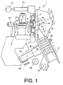
- the open-end spinning unit shown in Figure 1 carries total reference number 1.
- the spinning unit has a Rotor housing 2, in which the spinning cup of a spinning rotor 3 with rotates at high speed.
- the spinning rotor 3 is with his Rotor shaft 4 in the bearing gusset of a support disk bearing 5 supported and is supported by a machine-long Tangential belt 6, which is started by a pressure roller 7 is charged.
- the axial fixation of the rotor shaft 4 takes place via a permanent magnetic axial bearing 18, which in Figures 2 and 3 is shown in detail.
- the rotor housing 2 which is open towards the front, is closed during operation by a pivotably mounted cover element 8, into which a channel plate (not shown) with a seal 9 is inserted.
- the rotor housing 2 is also connected via a corresponding suction line 10 to a vacuum source 11, which generates the spinning vacuum required in the rotor housing 2.
- a channel plate adapter 12 is arranged in the cover element 8 and has the thread draw-off nozzle 13 and the mouth region of the fiber guide channel 14.
- a thread take-off tube 15 connects to the thread take-off nozzle 13.
- an opening roller housing 17 is fixed on the cover element 8, which is rotatably supported to a limited extent about a pivot axis 16.
- the cover element 8 furthermore has bearing brackets 19, 20 on the back for mounting an opening roller 21 or a sliver feed cylinder 22.
- the opening roller 21 is driven in the region of its whorl 23 by a circumferential, machine-long tangential belt 24, while the (not shown) drive of the sliver feed cylinder 22 is preferably carried out via a worm gear arrangement which is connected to a machine-long drive shaft 25.
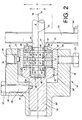
- Figure 2 shows the thrust bearing according to the invention in detail, wherein the axial bearing 18 is shown in section.
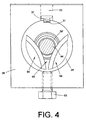
- a support disc 54 with shaft 55 in Figure 2 partially shown, while in FIG. 3 parts of two support disks 54 and 54 'are shown to determine the location of the bearing gusset 56 to make the rear support disks visible.
- a corresponding one The pair of support disks is spaced apart near the spinning cup of the spinning rotor 3, as can be seen in FIG. 1 is.
- the magnetic thrust bearing 18 consists of a static one Bearing component 27 which is axially adjustable in a bearing housing 26 is held.
- the active inventory components in the form of Permanent magnet rings 41 each arranged on both sides Pole rings 45 and 46 are within a bearing bush 28 arranged.
- a receptacle 29 is on the back via a thread 30 screwed to the bearing bush 28.
- the active ones Stock components 41 and 45, 46, which within the Bearing bush 28 are guided against one within one Bore 58 arranged in the front part of the bearing bush Ring insert 39 pressed. On the one hand, this results in a stable bearing construction, on the other hand an unproblematic Removability of the bearing, for example, within the Components to be replaced in the warehouse.
- the bearing bush 28 is within a bore 26 'of the Bearing housing 26 and the recording in a remote Bore 26 '' of the bearing housing 26 axially displaceable. Thereby can the stationary bearing component 27 axially adjusted exactly so be that the optimal spinning position of the Rotor cup results.
- a pin 32 engages one in a bore 34 inserted bolt 33 in a longitudinal groove 31 of the Bearing bush 28.
- a in a groove 59 of the receptacle 29 engaging pin 35 of an eccentric pin 36 can the axial adjustment of the static Bearing component 27 take place.
- the eccentric pin 36 is in one Bore 38 of the bearing housing 26 is used. He owns one Hexagon head 37, which has the possibility of connecting one Offers tools.
- a locking screw 53 which Bearing housing 26 braced against the bearing bush 28, the axial position of the static bearing component 27 are fixed.
- the rotor shaft 4 can through an opening in the rotor housing 2, through the gusset of the support disc bearing 5, by a Bore 57 of the ring insert 39 with its the dynamic Bearing component forming axial bearing part 44 'in the static Bearing component 27 are introduced, while the rest, mainly serving the radial bearing of the spinning rotor 3 Shaft part 44 remains outside of the axial bearing 18.
- Axial bearing part 44 'of the rotor shaft 4 are recesses 47 available that are filled with non-magnetic material, 47 different widths between these recesses Form webs 45 and 46.
- the rotor shaft 4 or the rotor 3 are made of steel with ferromagnetic properties.
- pole disks 42 and 43 have the same width on as the webs 45 and 46.
- the width B of the middle Pole disk 42 and the central web 46 is twice as large like the width b of the outer pole disks 43 and outer ones Web 45.
- the width b of the pole disks 43 1 mm, while the width B of the central pole disk 46 is 2 mm is.
- the width m of the permanent magnet rings 41 is 3.5 mm each.
- the ratio of the outer diameter D of the Permanent magnet rings 41 with inner diameter d is 1.7: 1.
- the permanent magnet rings 41 are axially polarized Rare earth magnets formed with the same poles (N / N or S / S).
- the non-magnetic, the Punctures 47 filling material is a copper alloy, for example brass, which is brazed onto the shaft is soldered.
- Other non-magnetic substances, that is, except Copper alloys also come in aluminum, tin or zinc also in question.
- These metallic substances have opposite an otherwise also possible plastic filling of the Punctures 47 have the advantage of higher heat resistance as well Stabilization of the rotor shaft 4 or its Thrust bearing part 44 '.
- the central axis 51 of the rotor is opposite the central axis 50 of the static bearing component 27 in the direction of the Bearing gusset 56 lowered.
- the radial adjustment takes place either by adjusting the support disc bearing 5 or of the thrust bearing 18.
- the entire bearing 5 is advantageous or 18 in a holder indicated in Fig. 1 within the Spinning unit 1 adjusted.
- This eccentric arrangement of the Rotor shaft 4 with its axial bearing part 44 'within the static bearing component 27 causes a reduction in Gap width between the webs 45 and 46 and Pole discs 42 and 43 on the bearing gusset 56 facing Page. Care must be taken that the distance is still is large enough to touch the one in alignment Metal body with resulting damage and heating too avoid.
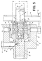
- a gradation of the rotor shaft 4 '(see FIG. 5) has the advantage, however, that the rotor shaft in the region of the axial bearing 18 has an increased natural frequency, which, depending on the other rotor dimensions and a high operating speed of the spinning rotor 3, ensures smooth running and, in particular, noise emission positively influenced.
- a radial adjustment of the ring insert 39 is in principle possible within the bore 58 in the bearing bush 28, especially about the security of avoiding the Maximize contact of the pole disks with the lands without however, the rotor shaft runs against the ring insert 39 effect during operation.
- the rotor shaft 4 is supported with the Shank end 48 on a support surface 49 '' of a sleeve 49, the overall from a friction-reducing, wear-resistant material.
- the piecing car exerts an essentially axial force on the Rotor cup 3 exercised, which starts up the shaft end 48 causes a support surface 48 'of the sleeve 49.
- the support surfaces 40 and 49 'and 49' 'becomes one prevents such deflection of the rotor shaft 4, which leads to a Contact between the webs 45 and 46 with the aligned ones Pole discs 42 and 43 could result.
- the socket 49 the consists entirely of a friction-reducing material, only the support surface 49 'and one over the same Angular range ⁇ , as within the ring insert 39 extending surface layer for the support surface 49 '' to provide the surface layer 40 axially spaced apart, but radially opposite, that is, by 180 ° is arranged pivoted.
- FIG. 4 also shows an alternative, that the annular gap between rotor shaft 4 and ring insert 39 'is constant. There is a risk of contact between rotor shaft 4 and ring insert 39 'during Operation of the spinning device reduced. At this point to point out that adjustment and Formation of the ring insert not in Figures 3 and 4 shown connection must have.
- Spinning rotors are used with a counter to reduce wear Wear protective coating, e.g. one Nickel / diamond coating.
- wear Wear protective coating e.g. one Nickel / diamond coating.
Landscapes
- Engineering & Computer Science (AREA)
- General Engineering & Computer Science (AREA)
- Mechanical Engineering (AREA)
- Textile Engineering (AREA)
- Spinning Or Twisting Of Yarns (AREA)
- Magnetic Bearings And Hydrostatic Bearings (AREA)
Claims (21)
- Palier pour un rotor de filage dans un métier à filer à bout librecaractérisé en ce que le palier de disque d'appui (5) du rotor (3) est disposé de telle manière par rapport à la composante de palier statique (27) du palier axial (18) que l'axe médian (51) du rotor (3) maintenu dans le gousset de logement (56) soit décalé en direction du gousset de logement (56) par rapport à l'axe médian (50) de la composante de palier statique et en ce que sur la partie de la composante de palier statique (27) dirigée vers les disque d'appui (54, 54'), en dehors du groupe composé des disques magnétiques et des disques polaires (41, 42, 43) et au moins sur une section d'angle α de 45° sur le côté du palier opposé au gousset de logement (56) se trouve une surface d'appui espacée par rapport à la tige de rotor (4) lors du fonctionnement et comprenant une couche de surface (40) réduisant le coefficient de frottement et protégée contre l'usure, dont l'espacement par rapport à la tige de rotor (4) est, lors du fonctionnement, d'au maximum la moitié de l'espacement le plus faible entre les disques polaires et les entretoises ferromagnétiques (45, 46).le rotor étant appuyé dans le gousset de logement d'un palier de disque d'appui et étant positionné dans le sens axial par un palier axial magnétique,le palier axial disposant d'une composante de palier statique (27) avec au moins deux bagues magnétiques permanentes (41) à polarisation axiale délimitées des deux côtés par des disques polaires (42, 43), qui sont disposées de telle manière dans un corps de palier que dans l'état monté, des pôles de même sens (N/N ou S/S) se trouvent en opposition réciproque etla tige de rotor (4) comprenant au moins trois entretoises ferromagnétiques (46) disposées avec un espacement par rapport aux disques polaires,
- Palier selon la revendication 1, caractérisé en ce que la surface d'appui (40) est disposée sur un insert d'anneau interchangeable (39) permettant le passage de la tige de rotor (4) dans le palier axial (18) et placé dans un coussinet de palier (28).
- Palier selon la revendication 2, caractérisé en ce que l'insert d'anneau (39) se compose d'un matériau réduisant le coefficient de frottement et protégé contre l'usure.
- Palier selon la revendication 1, 2 ou 3, caractérisé en ce que l'insert d'anneau (39, 39') peut être ajusté dans le sens radial, de sorte qu'une fente annulaire égale par rapport à la tige de rotor (4, 4'), ou une fente annulaire plus étroite du côté opposé au gousset de logement (56) est obtenue.
- Palier selon la revendication 2, 3 ou 4, caractérisé en ce que qu'une couche de surface réduisant le coefficient de frottement et protégée contre l'usure est également prévue sur une surface d'appui (49') espacée dans le sens axial par rapport à l'extrémité (48) de la tige de rotor lors du fonctionnement.
- Palier selon l'une des revendications 1 à 5, caractérisé en ce qu'à la hauteur de l'extrémité de la tige (48) du rotor (4), qui se trouve en dehors du groupe composé des disques magnétiques et des disques polaires (41, 42, 43), sur le côté dirigé vers le gousset de logement (56) se trouve une surface d'appui (49') espacée lors du fonctionnement et comprenant une couche de surface réduisant le coefficient de frottement et protégée contre l'usure.
- Palier selon la revendication 5 ou 6, caractérisé en ce que les surfaces d'appui (49', 49") sont formées par une douille (49), qui est maintenue dans un réceptacle (29).
- Palier selon la revendication 7, caractérisé en ce que la douille (49) se compose d'un matériau réduisant le coefficient de frottement et protégé contre l'usure.
- Palier selon l'une des revendications 1 à 8, caractérisé en ce que le matériau réduisant le coefficient de frottement est un matériau à base de fibres de carbone ou de graphite.
- Palier selon l'une des revendications 1 à 9, caractérisé en ce que le rapport entre le déport de l'axe médian (51) du rotor (4) vis-à-vis de l'axe médian (50) de la composante de palier statique (27) et la différence entre le diamètre intérieur des anneaux polaires (42, 43) et le diamètre extérieur des entretoises (45, 46) qui leur sont opposées est de 1 : 3,0 à 1 : 8,0 et de préférence de 1 : 4 à 1 : 6,5.
- Palier selon la revendication 10, caractérisé en ce que le déport entre l'axe médian du rotor et l'axe médian de la composante de palier statique est de 0,2 à 1,0 mm et de préférence de 0,25 à 0,4 mm.
- Palier selon l'une des revendications 1 à 11, caractérisé en ce qu'un revêtement réduisant l'usure du rotor de filage (4) se limite à la partie (44) du rotor de filage (4) située à l'extérieur du palier axial (18).
- Palier selon l'une des revendications 1 à 12, caractérisé en ce que les bagues magnétiques permanentes (41) présentent un rapport entre le diamètre extérieur D et le diamètre intérieur d de 1,5 : 1 à 2,8 : 1 et de préférence de 1,7 : 1 à 1,8 : 1 et ont une largeur m qui présente avec la largeur b des disques polaires extérieurs un rapport de 2,5 : 1 à 5,0 : 1 et de préférence de 3,0 : 1 à 3,9 : 1 et avec une largeur d'un disque polaire situé entre les bagues magnétiques permanentes un rapport de 1,3 : 1 à 2,5 : 1 et de préférence de 1,5 : 1 à 2,0 : 1.
- Palier selon la revendication 13, caractérisé en ce que la largeur b des disques polaires extérieurs est de 0,5 à 1,5 mm, tandis que la largeur B des disques polaires situés entre les bagues magnétiques permanentes est de 1,0 à 3,0 mm.
- Palier selon la revendication 14, caractérisé en ce que la largeur (B, b) des disques polaires (42, 43) correspond à la largeur des entretoises ferromagnétiques (45, 46) entre des encoches (47) dans la tige de rotor (4) du rotor de filage (3) remplies d'un matériau amagnétique, qui sont en alignement avec les disques polaires.
- Palier selon la revendication 15, caractérisé en ce que le matériau amagnétique est du cuivre ou un alliage de cuivre.
- Palier selon l'une des revendications 13 à 16, caractérisé en ce que les bagues magnétiques permanentes (41) sont des aimants de terres rares.
- Palier selon l'une des revendications 13 à 17, caractérisé en ce que la totalité des bords opposés des disques polaires (42, 43) et des entretoises (45, 46) ne sont pas arrondis.
- Palier selon l'une des revendications 13 à 18, caractérisé en ce que la tige de rotor (4) présente un diamètre qui reste constant sur toute sa longueur.
- Palier selon l'une des revendications 13 à 18, caractérisé en ce que dans sa partie de palier axial (44'), la tige de rotor (4) présente par rapport au diamètre R de l'autre partie (44) disposée en dehors du palier axial un diamètre r de tige de rotor réduit de 1/8 à 1/2 et de préférence de 1/4 à 3/8, qui est encore réduit par les encoches (47), les composants de palier statiques (27) étant adaptés pour un maintien au moins approximatif des largeurs de fentes entre les disques polaires (42, 43) et les entretoises (45, 46).
- Palier selon la revendication 19 ou 20, caractérisé en ce que la profondeur des encoches (47, 47') représente 0,1 à 0,3 fois le diamètre des entretoises (45', 46').
Applications Claiming Priority (2)
| Application Number | Priority Date | Filing Date | Title |
|---|---|---|---|
| DE19910279A DE19910279A1 (de) | 1999-03-09 | 1999-03-09 | Lagerung eines Spinnrotors einer Offenend-Spinnvorrichtung |
| DE19910279 | 1999-03-09 |
Publications (2)
| Publication Number | Publication Date |
|---|---|
| EP1043431A1 EP1043431A1 (fr) | 2000-10-11 |
| EP1043431B1 true EP1043431B1 (fr) | 2002-10-02 |
Family
ID=7900209
Family Applications (1)
| Application Number | Title | Priority Date | Filing Date |
|---|---|---|---|
| EP00103286A Expired - Lifetime EP1043431B1 (fr) | 1999-03-09 | 2000-02-18 | Palier pour un rotor de filage dans un métier à filer à bout libre |
Country Status (5)
| Country | Link |
|---|---|
| US (1) | US6340855B1 (fr) |
| EP (1) | EP1043431B1 (fr) |
| JP (1) | JP2000273724A (fr) |
| CZ (1) | CZ299186B6 (fr) |
| DE (2) | DE19910279A1 (fr) |
Cited By (2)
| Publication number | Priority date | Publication date | Assignee | Title |
|---|---|---|---|---|
| US8072105B2 (en) | 2008-11-12 | 2011-12-06 | Oerlikon Textile Gmbh & Co. Kg | Axial bearing |
| CN103409862A (zh) * | 2013-08-22 | 2013-11-27 | 宁波冠蓝机械科技有限公司 | 一种转杯纺纱机的转杯间隙调节结构 |
Families Citing this family (7)
| Publication number | Priority date | Publication date | Assignee | Title |
|---|---|---|---|---|
| DE19955829A1 (de) | 1999-11-20 | 2001-05-23 | Schlafhorst & Co W | Offenend-Spinnvorrichtung |
| DE10050694A1 (de) * | 2000-10-13 | 2002-04-18 | Schlafhorst & Co W | Lagerung für eine Offenend-Spinnvorrichtung |
| DE10200743A1 (de) * | 2002-01-10 | 2003-07-24 | Rieter Ingolstadt Spinnerei | Grundkörper für die Stützscheibe einer OE-Rotorlagerung |
| DE102008008854A1 (de) | 2008-02-13 | 2009-08-20 | Oerlikon Textile Gmbh & Co. Kg | Axiallager |
| FR2962505B1 (fr) | 2010-07-08 | 2012-08-10 | Mecanique Magnetique Sa | Palier magnetique a reglage axial et procede de montage |
| CN115046878B (zh) * | 2022-06-14 | 2023-06-20 | 燕山大学 | 非金属材料双形式摩擦磨损检测装置 |
| CN118088578B (zh) * | 2024-03-05 | 2025-02-07 | 江苏科技大学 | 一种用于复合材料轴的磁轴承结构及其装配方法 |
Family Cites Families (10)
| Publication number | Priority date | Publication date | Assignee | Title |
|---|---|---|---|---|
| AT270459B (de) | 1966-03-01 | 1969-04-25 | Vyzk Ustav Bavlnarsky | Vorrichtung zur Lagerung und zum Antrieb der rotierenden Spinnkammer |
| DE2108590A1 (de) * | 1971-02-23 | 1972-09-07 | Siemens Ag | Anordnung zur Lagerung einer hochtourig, insbesondere elektromotorisch angetriebenen Welle |
| DE2514734C2 (de) | 1975-04-04 | 1982-10-28 | Stahlecker, Fritz, 7347 Bad Überkingen | Lagerung für einen Offenend-Spinnrotor |
| DE3047606C2 (de) | 1979-12-26 | 1985-07-11 | Ichikawa Iron Works Co. Ltd., Kiryu, Gumma | Lageranordnung für einen länglichen, um seine Längsachse drehbaren Drehkörper |
| DE3942612C2 (de) * | 1989-12-25 | 2003-05-08 | Rieter Ingolstadt Spinnerei | Offenend-Spinnvorrichtung |
| US5622040A (en) | 1994-12-21 | 1997-04-22 | W. Schlafhorst Ag & Co. | Bearing for an open-end spinning rotor |
| DE19729191B4 (de) * | 1997-07-09 | 2008-01-10 | Oerlikon Textile Gmbh & Co. Kg | Offenend-Spinnvorrichtung mit einem Spinnrotor |
| EP0926275B1 (fr) * | 1997-12-18 | 2003-09-10 | W. SCHLAFHORST AG & CO. | Métier à filer à bout ouvert pour fabriquer des fils à torsion S ou Z |
| EP0955397B1 (fr) * | 1998-05-04 | 2004-04-21 | Saurer GmbH & Co. KG | Métier à filer à bout libre |
| DE19827606A1 (de) * | 1998-06-20 | 1999-12-23 | Schlafhorst & Co W | Lageranordnung für eine Offenend-Spinnvorrichtung |
-
1999
- 1999-03-09 DE DE19910279A patent/DE19910279A1/de not_active Withdrawn
-
2000
- 2000-02-18 EP EP00103286A patent/EP1043431B1/fr not_active Expired - Lifetime
- 2000-02-18 DE DE50000578T patent/DE50000578D1/de not_active Expired - Lifetime
- 2000-02-24 US US09/512,561 patent/US6340855B1/en not_active Expired - Lifetime
- 2000-03-06 JP JP2000061112A patent/JP2000273724A/ja active Pending
- 2000-03-07 CZ CZ20000831A patent/CZ299186B6/cs not_active IP Right Cessation
Cited By (3)
| Publication number | Priority date | Publication date | Assignee | Title |
|---|---|---|---|---|
| US8072105B2 (en) | 2008-11-12 | 2011-12-06 | Oerlikon Textile Gmbh & Co. Kg | Axial bearing |
| CN103409862A (zh) * | 2013-08-22 | 2013-11-27 | 宁波冠蓝机械科技有限公司 | 一种转杯纺纱机的转杯间隙调节结构 |
| CN103409862B (zh) * | 2013-08-22 | 2015-11-18 | 宁波冠蓝机械科技有限公司 | 一种转杯纺纱机的转杯间隙调节结构 |
Also Published As
| Publication number | Publication date |
|---|---|
| US6340855B1 (en) | 2002-01-22 |
| DE50000578D1 (de) | 2002-11-07 |
| EP1043431A1 (fr) | 2000-10-11 |
| CZ299186B6 (cs) | 2008-05-14 |
| JP2000273724A (ja) | 2000-10-03 |
| DE19910279A1 (de) | 2000-09-14 |
| CZ2000831A3 (cs) | 2000-10-11 |
Similar Documents
| Publication | Publication Date | Title |
|---|---|---|
| DE1800761C3 (de) | Vorrichtung zum Zerhacken endloser Glasfaserstränge | |
| EP1043431B1 (fr) | Palier pour un rotor de filage dans un métier à filer à bout libre | |
| DE2047569A1 (de) | Lagerung für Spinnturbinen | |
| DE19729191B4 (de) | Offenend-Spinnvorrichtung mit einem Spinnrotor | |
| DE19720795A1 (de) | Fadenbremse und damit ausgerüstete Textilmaschine und Fadenliefervorrichtung | |
| EP1101845B1 (fr) | Palier pour un rotor de filage dans une machine de filature à bout ouvert | |
| DE2524093A1 (de) | Zufuehr- und aufloeseeinrichtung fuer ein offenend-spinnaggregat | |
| EP2090681B1 (fr) | Palier axial | |
| EP2187075A1 (fr) | Palier axial | |
| EP0794273A1 (fr) | Métier à filer à bout libre | |
| EP0476407B1 (fr) | Appareil pour le guidage d'un chapeau d'une machine de cardage pour le coton ou pour la laine | |
| DE19549680B4 (de) | Auflösewalze für eine Offenend-Spinnvorrichtung | |
| WO2007079794A1 (fr) | Rotor de filage a extremite ouverte pour machine textile qui fabrique des bobines croisees | |
| DE29920395U1 (de) | Lagerung für eine Offenend-Spinnvorrichtung | |
| EP0747517B1 (fr) | Cylindre ouvreur pour un métier à filer à bout libéré | |
| DE4423605B4 (de) | Lagerung für einen Offenend-Spinnrotor | |
| DE69809068T2 (de) | Antriebsrad | |
| DE2363768A1 (de) | Spulentragvorrichtung | |
| DE4117175A1 (de) | Schaft fuer einen oe-spinnrotor | |
| DE29920394U1 (de) | Lagerung für eine Offenend-Spinnvorrichtung | |
| DE19528727C2 (de) | Offen-End-Rotorspinnmaschine | |
| DE4418723C1 (de) | Offenend-Rotorspinnvorrichtung | |
| DE3417705A1 (de) | Oe-rotorspinnmaschine mit einer vielzahl von spinnaggregaten | |
| DE10050694A1 (de) | Lagerung für eine Offenend-Spinnvorrichtung | |
| EP3156527B1 (fr) | Dispositif de filature à rotor à bout libre avec un rotor fileur, stocké avec sa tige de rotor dans le coin d'un palier à disque d'appui |
Legal Events
| Date | Code | Title | Description |
|---|---|---|---|
| PUAI | Public reference made under article 153(3) epc to a published international application that has entered the european phase |
Free format text: ORIGINAL CODE: 0009012 |
|
| AK | Designated contracting states |
Kind code of ref document: A1 Designated state(s): CH DE IT LI |
|
| AX | Request for extension of the european patent |
Free format text: AL;LT;LV;MK;RO;SI |
|
| 17P | Request for examination filed |
Effective date: 20010411 |
|
| AKX | Designation fees paid |
Free format text: CH DE IT LI |
|
| GRAG | Despatch of communication of intention to grant |
Free format text: ORIGINAL CODE: EPIDOS AGRA |
|
| 17Q | First examination report despatched |
Effective date: 20011206 |
|
| GRAG | Despatch of communication of intention to grant |
Free format text: ORIGINAL CODE: EPIDOS AGRA |
|
| GRAH | Despatch of communication of intention to grant a patent |
Free format text: ORIGINAL CODE: EPIDOS IGRA |
|
| GRAH | Despatch of communication of intention to grant a patent |
Free format text: ORIGINAL CODE: EPIDOS IGRA |
|
| GRAA | (expected) grant |
Free format text: ORIGINAL CODE: 0009210 |
|
| AK | Designated contracting states |
Kind code of ref document: B1 Designated state(s): CH DE IT LI |
|
| REG | Reference to a national code |
Ref country code: CH Ref legal event code: EP |
|
| REF | Corresponds to: |
Ref document number: 50000578 Country of ref document: DE Date of ref document: 20021107 |
|
| PLBE | No opposition filed within time limit |
Free format text: ORIGINAL CODE: 0009261 |
|
| STAA | Information on the status of an ep patent application or granted ep patent |
Free format text: STATUS: NO OPPOSITION FILED WITHIN TIME LIMIT |
|
| 26N | No opposition filed |
Effective date: 20030703 |
|
| PGFP | Annual fee paid to national office [announced via postgrant information from national office to epo] |
Ref country code: CH Payment date: 20060220 Year of fee payment: 7 |
|
| PGFP | Annual fee paid to national office [announced via postgrant information from national office to epo] |
Ref country code: IT Payment date: 20060228 Year of fee payment: 7 |
|
| PG25 | Lapsed in a contracting state [announced via postgrant information from national office to epo] |
Ref country code: LI Free format text: LAPSE BECAUSE OF NON-PAYMENT OF DUE FEES Effective date: 20070228 Ref country code: CH Free format text: LAPSE BECAUSE OF NON-PAYMENT OF DUE FEES Effective date: 20070228 |
|
| REG | Reference to a national code |
Ref country code: CH Ref legal event code: PL |
|
| PG25 | Lapsed in a contracting state [announced via postgrant information from national office to epo] |
Ref country code: IT Free format text: LAPSE BECAUSE OF NON-PAYMENT OF DUE FEES Effective date: 20070218 |
|
| PGFP | Annual fee paid to national office [announced via postgrant information from national office to epo] |
Ref country code: DE Payment date: 20120312 Year of fee payment: 13 |
|
| REG | Reference to a national code |
Ref country code: DE Ref legal event code: R119 Ref document number: 50000578 Country of ref document: DE Effective date: 20130903 |
|
| PG25 | Lapsed in a contracting state [announced via postgrant information from national office to epo] |
Ref country code: DE Free format text: LAPSE BECAUSE OF NON-PAYMENT OF DUE FEES Effective date: 20130903 |