EP1043480A2 - Refroidissement à pellicule des parois chaudes - Google Patents
Refroidissement à pellicule des parois chaudes Download PDFInfo
- Publication number
- EP1043480A2 EP1043480A2 EP00302884A EP00302884A EP1043480A2 EP 1043480 A2 EP1043480 A2 EP 1043480A2 EP 00302884 A EP00302884 A EP 00302884A EP 00302884 A EP00302884 A EP 00302884A EP 1043480 A2 EP1043480 A2 EP 1043480A2
- Authority
- EP
- European Patent Office
- Prior art keywords
- substrate
- exit site
- passage hole
- hole
- cooling
- Prior art date
- Legal status (The legal status is an assumption and is not a legal conclusion. Google has not performed a legal analysis and makes no representation as to the accuracy of the status listed.)
- Withdrawn
Links
- 238000001816 cooling Methods 0.000 title claims abstract description 94
- 239000000758 substrate Substances 0.000 claims abstract description 153
- 238000000034 method Methods 0.000 claims abstract description 77
- 239000002826 coolant Substances 0.000 claims abstract description 70
- 238000000576 coating method Methods 0.000 claims abstract description 30
- 239000011248 coating agent Substances 0.000 claims abstract description 24
- 239000012720 thermal barrier coating Substances 0.000 abstract description 35
- 229910000601 superalloy Inorganic materials 0.000 abstract description 6
- 239000000463 material Substances 0.000 description 33
- 238000007664 blowing Methods 0.000 description 29
- 239000010410 layer Substances 0.000 description 20
- 238000002485 combustion reaction Methods 0.000 description 18
- 229910052751 metal Inorganic materials 0.000 description 17
- 239000002184 metal Substances 0.000 description 17
- MCMNRKCIXSYSNV-UHFFFAOYSA-N Zirconium dioxide Chemical compound O=[Zr]=O MCMNRKCIXSYSNV-UHFFFAOYSA-N 0.000 description 12
- 230000000873 masking effect Effects 0.000 description 9
- 238000012360 testing method Methods 0.000 description 9
- 239000000919 ceramic Substances 0.000 description 7
- 238000005553 drilling Methods 0.000 description 7
- 239000007921 spray Substances 0.000 description 7
- XLYOFNOQVPJJNP-UHFFFAOYSA-N water Substances O XLYOFNOQVPJJNP-UHFFFAOYSA-N 0.000 description 7
- PXHVJJICTQNCMI-UHFFFAOYSA-N Nickel Chemical compound [Ni] PXHVJJICTQNCMI-UHFFFAOYSA-N 0.000 description 6
- 230000035515 penetration Effects 0.000 description 6
- 238000004088 simulation Methods 0.000 description 6
- 239000012809 cooling fluid Substances 0.000 description 5
- 230000006872 improvement Effects 0.000 description 5
- 230000015572 biosynthetic process Effects 0.000 description 4
- 230000008569 process Effects 0.000 description 4
- 229910052782 aluminium Inorganic materials 0.000 description 3
- XAGFODPZIPBFFR-UHFFFAOYSA-N aluminium Chemical compound [Al] XAGFODPZIPBFFR-UHFFFAOYSA-N 0.000 description 3
- 238000013459 approach Methods 0.000 description 3
- 239000000446 fuel Substances 0.000 description 3
- 238000005259 measurement Methods 0.000 description 3
- 239000007769 metal material Substances 0.000 description 3
- 238000012986 modification Methods 0.000 description 3
- 230000004048 modification Effects 0.000 description 3
- 229910052759 nickel Inorganic materials 0.000 description 3
- SIWVEOZUMHYXCS-UHFFFAOYSA-N oxo(oxoyttriooxy)yttrium Chemical compound O=[Y]O[Y]=O SIWVEOZUMHYXCS-UHFFFAOYSA-N 0.000 description 3
- 229920005989 resin Polymers 0.000 description 3
- 239000011347 resin Substances 0.000 description 3
- 239000004593 Epoxy Substances 0.000 description 2
- XEEYBQQBJWHFJM-UHFFFAOYSA-N Iron Chemical compound [Fe] XEEYBQQBJWHFJM-UHFFFAOYSA-N 0.000 description 2
- PPBRXRYQALVLMV-UHFFFAOYSA-N Styrene Chemical compound C=CC1=CC=CC=C1 PPBRXRYQALVLMV-UHFFFAOYSA-N 0.000 description 2
- 230000009286 beneficial effect Effects 0.000 description 2
- 230000008901 benefit Effects 0.000 description 2
- 239000011247 coating layer Substances 0.000 description 2
- 238000000151 deposition Methods 0.000 description 2
- 230000008021 deposition Effects 0.000 description 2
- 238000005328 electron beam physical vapour deposition Methods 0.000 description 2
- 238000005516 engineering process Methods 0.000 description 2
- 239000003822 epoxy resin Substances 0.000 description 2
- 238000002474 experimental method Methods 0.000 description 2
- 239000012530 fluid Substances 0.000 description 2
- 230000004907 flux Effects 0.000 description 2
- 238000003754 machining Methods 0.000 description 2
- 229910001092 metal group alloy Inorganic materials 0.000 description 2
- 150000002739 metals Chemical class 0.000 description 2
- 239000000203 mixture Substances 0.000 description 2
- 230000036961 partial effect Effects 0.000 description 2
- 229920000647 polyepoxide Polymers 0.000 description 2
- 230000001681 protective effect Effects 0.000 description 2
- 239000000126 substance Substances 0.000 description 2
- 229920001169 thermoplastic Polymers 0.000 description 2
- 239000012815 thermoplastic material Substances 0.000 description 2
- 239000004416 thermosoftening plastic Substances 0.000 description 2
- 238000011144 upstream manufacturing Methods 0.000 description 2
- 229920000178 Acrylic resin Polymers 0.000 description 1
- 239000004925 Acrylic resin Substances 0.000 description 1
- 239000004952 Polyamide Substances 0.000 description 1
- 229910000831 Steel Inorganic materials 0.000 description 1
- RTAQQCXQSZGOHL-UHFFFAOYSA-N Titanium Chemical compound [Ti] RTAQQCXQSZGOHL-UHFFFAOYSA-N 0.000 description 1
- 238000005299 abrasion Methods 0.000 description 1
- 239000000853 adhesive Substances 0.000 description 1
- 230000001070 adhesive effect Effects 0.000 description 1
- 238000003915 air pollution Methods 0.000 description 1
- 229920000180 alkyd Polymers 0.000 description 1
- 230000004888 barrier function Effects 0.000 description 1
- 238000005422 blasting Methods 0.000 description 1
- 238000005219 brazing Methods 0.000 description 1
- QHIWVLPBUQWDMQ-UHFFFAOYSA-N butyl prop-2-enoate;methyl 2-methylprop-2-enoate;prop-2-enoic acid Chemical compound OC(=O)C=C.COC(=O)C(C)=C.CCCCOC(=O)C=C QHIWVLPBUQWDMQ-UHFFFAOYSA-N 0.000 description 1
- BRPQOXSCLDDYGP-UHFFFAOYSA-N calcium oxide Chemical compound [O-2].[Ca+2] BRPQOXSCLDDYGP-UHFFFAOYSA-N 0.000 description 1
- 239000000292 calcium oxide Substances 0.000 description 1
- ODINCKMPIJJUCX-UHFFFAOYSA-N calcium oxide Inorganic materials [Ca]=O ODINCKMPIJJUCX-UHFFFAOYSA-N 0.000 description 1
- 230000015556 catabolic process Effects 0.000 description 1
- 229910010293 ceramic material Inorganic materials 0.000 description 1
- 229910000420 cerium oxide Inorganic materials 0.000 description 1
- 238000012512 characterization method Methods 0.000 description 1
- 238000004140 cleaning Methods 0.000 description 1
- 229910017052 cobalt Inorganic materials 0.000 description 1
- 239000010941 cobalt Substances 0.000 description 1
- GUTLYIVDDKVIGB-UHFFFAOYSA-N cobalt atom Chemical compound [Co] GUTLYIVDDKVIGB-UHFFFAOYSA-N 0.000 description 1
- 230000000052 comparative effect Effects 0.000 description 1
- 150000001875 compounds Chemical class 0.000 description 1
- 238000005094 computer simulation Methods 0.000 description 1
- 238000007796 conventional method Methods 0.000 description 1
- 229920001577 copolymer Polymers 0.000 description 1
- 230000007423 decrease Effects 0.000 description 1
- 230000003247 decreasing effect Effects 0.000 description 1
- 238000006731 degradation reaction Methods 0.000 description 1
- 238000013461 design Methods 0.000 description 1
- 238000009792 diffusion process Methods 0.000 description 1
- 230000000694 effects Effects 0.000 description 1
- 238000009760 electrical discharge machining Methods 0.000 description 1
- 239000003344 environmental pollutant Substances 0.000 description 1
- 238000005530 etching Methods 0.000 description 1
- 238000001125 extrusion Methods 0.000 description 1
- 239000000945 filler Substances 0.000 description 1
- 238000011049 filling Methods 0.000 description 1
- 239000007850 fluorescent dye Substances 0.000 description 1
- LNEPOXFFQSENCJ-UHFFFAOYSA-N haloperidol Chemical compound C1CC(O)(C=2C=CC(Cl)=CC=2)CCN1CCCC(=O)C1=CC=C(F)C=C1 LNEPOXFFQSENCJ-UHFFFAOYSA-N 0.000 description 1
- 238000010348 incorporation Methods 0.000 description 1
- 229910052742 iron Inorganic materials 0.000 description 1
- 230000001788 irregular Effects 0.000 description 1
- 238000001499 laser induced fluorescence spectroscopy Methods 0.000 description 1
- 230000000670 limiting effect Effects 0.000 description 1
- 239000004973 liquid crystal related substance Substances 0.000 description 1
- 239000000395 magnesium oxide Substances 0.000 description 1
- CPLXHLVBOLITMK-UHFFFAOYSA-N magnesium oxide Inorganic materials [Mg]=O CPLXHLVBOLITMK-UHFFFAOYSA-N 0.000 description 1
- AXZKOIWUVFPNLO-UHFFFAOYSA-N magnesium;oxygen(2-) Chemical compound [O-2].[Mg+2] AXZKOIWUVFPNLO-UHFFFAOYSA-N 0.000 description 1
- 238000004519 manufacturing process Methods 0.000 description 1
- 238000002844 melting Methods 0.000 description 1
- 230000008018 melting Effects 0.000 description 1
- 238000005555 metalworking Methods 0.000 description 1
- BMMGVYCKOGBVEV-UHFFFAOYSA-N oxo(oxoceriooxy)cerium Chemical compound [Ce]=O.O=[Ce]=O BMMGVYCKOGBVEV-UHFFFAOYSA-N 0.000 description 1
- 238000000059 patterning Methods 0.000 description 1
- ISWSIDIOOBJBQZ-UHFFFAOYSA-N phenol group Chemical group C1(=CC=CC=C1)O ISWSIDIOOBJBQZ-UHFFFAOYSA-N 0.000 description 1
- 229920001568 phenolic resin Polymers 0.000 description 1
- 239000005011 phenolic resin Substances 0.000 description 1
- 238000005240 physical vapour deposition Methods 0.000 description 1
- 239000004033 plastic Substances 0.000 description 1
- 239000004014 plasticizer Substances 0.000 description 1
- 231100000719 pollutant Toxicity 0.000 description 1
- 229920002647 polyamide Polymers 0.000 description 1
- 229920000728 polyester Polymers 0.000 description 1
- 229920000642 polymer Polymers 0.000 description 1
- 229920000098 polyolefin Polymers 0.000 description 1
- 239000000843 powder Substances 0.000 description 1
- 239000002243 precursor Substances 0.000 description 1
- 238000012545 processing Methods 0.000 description 1
- 239000011253 protective coating Substances 0.000 description 1
- 238000000197 pyrolysis Methods 0.000 description 1
- 230000009467 reduction Effects 0.000 description 1
- 239000003870 refractory metal Substances 0.000 description 1
- HYXGAEYDKFCVMU-UHFFFAOYSA-N scandium oxide Chemical compound O=[Sc]O[Sc]=O HYXGAEYDKFCVMU-UHFFFAOYSA-N 0.000 description 1
- 238000000926 separation method Methods 0.000 description 1
- 238000007493 shaping process Methods 0.000 description 1
- 239000007787 solid Substances 0.000 description 1
- 239000002904 solvent Substances 0.000 description 1
- 239000010935 stainless steel Substances 0.000 description 1
- 229910001220 stainless steel Inorganic materials 0.000 description 1
- 239000010959 steel Substances 0.000 description 1
- 229920001059 synthetic polymer Polymers 0.000 description 1
- 229920001187 thermosetting polymer Polymers 0.000 description 1
- 239000010936 titanium Substances 0.000 description 1
- 229910052719 titanium Inorganic materials 0.000 description 1
- 238000003466 welding Methods 0.000 description 1
- 229910001233 yttria-stabilized zirconia Inorganic materials 0.000 description 1
Images


Classifications
-
- F—MECHANICAL ENGINEERING; LIGHTING; HEATING; WEAPONS; BLASTING
- F23—COMBUSTION APPARATUS; COMBUSTION PROCESSES
- F23R—GENERATING COMBUSTION PRODUCTS OF HIGH PRESSURE OR HIGH VELOCITY, e.g. GAS-TURBINE COMBUSTION CHAMBERS
- F23R3/00—Continuous combustion chambers using liquid or gaseous fuel
- F23R3/02—Continuous combustion chambers using liquid or gaseous fuel characterised by the air-flow or gas-flow configuration
- F23R3/04—Air inlet arrangements
- F23R3/06—Arrangement of apertures along the flame tube
-
- F—MECHANICAL ENGINEERING; LIGHTING; HEATING; WEAPONS; BLASTING
- F01—MACHINES OR ENGINES IN GENERAL; ENGINE PLANTS IN GENERAL; STEAM ENGINES
- F01D—NON-POSITIVE DISPLACEMENT MACHINES OR ENGINES, e.g. STEAM TURBINES
- F01D5/00—Blades; Blade-carrying members; Heating, heat-insulating, cooling or antivibration means on the blades or the members
- F01D5/12—Blades
- F01D5/14—Form or construction
- F01D5/18—Hollow blades, i.e. blades with cooling or heating channels or cavities; Heating, heat-insulating or cooling means on blades
- F01D5/186—Film cooling
-
- F—MECHANICAL ENGINEERING; LIGHTING; HEATING; WEAPONS; BLASTING
- F01—MACHINES OR ENGINES IN GENERAL; ENGINE PLANTS IN GENERAL; STEAM ENGINES
- F01D—NON-POSITIVE DISPLACEMENT MACHINES OR ENGINES, e.g. STEAM TURBINES
- F01D5/00—Blades; Blade-carrying members; Heating, heat-insulating, cooling or antivibration means on the blades or the members
- F01D5/12—Blades
- F01D5/28—Selecting particular materials; Particular measures relating thereto; Measures against erosion or corrosion
- F01D5/288—Protective coatings for blades
-
- F—MECHANICAL ENGINEERING; LIGHTING; HEATING; WEAPONS; BLASTING
- F23—COMBUSTION APPARATUS; COMBUSTION PROCESSES
- F23R—GENERATING COMBUSTION PRODUCTS OF HIGH PRESSURE OR HIGH VELOCITY, e.g. GAS-TURBINE COMBUSTION CHAMBERS
- F23R3/00—Continuous combustion chambers using liquid or gaseous fuel
- F23R3/002—Wall structures
-
- F—MECHANICAL ENGINEERING; LIGHTING; HEATING; WEAPONS; BLASTING
- F05—INDEXING SCHEMES RELATING TO ENGINES OR PUMPS IN VARIOUS SUBCLASSES OF CLASSES F01-F04
- F05D—INDEXING SCHEME FOR ASPECTS RELATING TO NON-POSITIVE-DISPLACEMENT MACHINES OR ENGINES, GAS-TURBINES OR JET-PROPULSION PLANTS
- F05D2260/00—Function
- F05D2260/20—Heat transfer, e.g. cooling
- F05D2260/202—Heat transfer, e.g. cooling by film cooling
-
- F—MECHANICAL ENGINEERING; LIGHTING; HEATING; WEAPONS; BLASTING
- F05—INDEXING SCHEMES RELATING TO ENGINES OR PUMPS IN VARIOUS SUBCLASSES OF CLASSES F01-F04
- F05D—INDEXING SCHEME FOR ASPECTS RELATING TO NON-POSITIVE-DISPLACEMENT MACHINES OR ENGINES, GAS-TURBINES OR JET-PROPULSION PLANTS
- F05D2260/00—Function
- F05D2260/20—Heat transfer, e.g. cooling
- F05D2260/221—Improvement of heat transfer
- F05D2260/2212—Improvement of heat transfer by creating turbulence
-
- Y—GENERAL TAGGING OF NEW TECHNOLOGICAL DEVELOPMENTS; GENERAL TAGGING OF CROSS-SECTIONAL TECHNOLOGIES SPANNING OVER SEVERAL SECTIONS OF THE IPC; TECHNICAL SUBJECTS COVERED BY FORMER USPC CROSS-REFERENCE ART COLLECTIONS [XRACs] AND DIGESTS
- Y02—TECHNOLOGIES OR APPLICATIONS FOR MITIGATION OR ADAPTATION AGAINST CLIMATE CHANGE
- Y02T—CLIMATE CHANGE MITIGATION TECHNOLOGIES RELATED TO TRANSPORTATION
- Y02T50/00—Aeronautics or air transport
- Y02T50/60—Efficient propulsion technologies, e.g. for aircraft
-
- Y—GENERAL TAGGING OF NEW TECHNOLOGICAL DEVELOPMENTS; GENERAL TAGGING OF CROSS-SECTIONAL TECHNOLOGIES SPANNING OVER SEVERAL SECTIONS OF THE IPC; TECHNICAL SUBJECTS COVERED BY FORMER USPC CROSS-REFERENCE ART COLLECTIONS [XRACs] AND DIGESTS
- Y10—TECHNICAL SUBJECTS COVERED BY FORMER USPC
- Y10T—TECHNICAL SUBJECTS COVERED BY FORMER US CLASSIFICATION
- Y10T428/00—Stock material or miscellaneous articles
- Y10T428/24—Structurally defined web or sheet [e.g., overall dimension, etc.]
- Y10T428/24273—Structurally defined web or sheet [e.g., overall dimension, etc.] including aperture
-
- Y—GENERAL TAGGING OF NEW TECHNOLOGICAL DEVELOPMENTS; GENERAL TAGGING OF CROSS-SECTIONAL TECHNOLOGIES SPANNING OVER SEVERAL SECTIONS OF THE IPC; TECHNICAL SUBJECTS COVERED BY FORMER USPC CROSS-REFERENCE ART COLLECTIONS [XRACs] AND DIGESTS
- Y10—TECHNICAL SUBJECTS COVERED BY FORMER USPC
- Y10T—TECHNICAL SUBJECTS COVERED BY FORMER US CLASSIFICATION
- Y10T428/00—Stock material or miscellaneous articles
- Y10T428/24—Structurally defined web or sheet [e.g., overall dimension, etc.]
- Y10T428/24273—Structurally defined web or sheet [e.g., overall dimension, etc.] including aperture
- Y10T428/24322—Composite web or sheet
Definitions
- This invention relates generally to articles which are used in a high-temperature environment. More particularly, it relates to methods for protecting the articles from damage in such an environment.
- Various types of materials are used for components which may be exposed to a high-temperature environment.
- Aircraft engine parts represent examples of these types of components.
- Peak gas temperatures present in the turbine engine of an aircraft are maintained as high as possible for operating efficiency.
- Turbine blades and other elements of the engine are usually made of metal alloys which can resist the high-temperature environment, e.g., superalloys, which have an operating temperature limit of about 1000°C-1150°C. Operation above these temperatures may cause the various turbine elements to fail and damage the engine.
- TBC thermal barrier coatings
- a pattern of cooling holes may extend from a relatively cool surface of a combustion chamber to a "hot" surface which is exposed to gas flow at combustion temperatures of at least about 1000° C. (The drawings described below will serve to illustrate this concept.)
- the technique is sometimes referred to as "discrete hole fun cooling”. Cooling air, usually bled off from the engine's compressor, is typically bypassed around the engine's combustion zone and fed through the cooling holes to the hot surface.
- the ratio of the cooling air mass flux (the product of air velocity times density) to the mass flux of the hot gas flowing along the hot surface (e.g., a combustion product) is sometimes referred to as the "blowing ratio".
- the cooling air forms a protective "film" between the metal surface and the hot gas flow, preventing melting or other degradation of the component.
- Film cooling performance may be characterized in several ways.
- One relevant indication of performance is known as the adiabatic wall film cooling effectiveness, sometimes referred to herein as the "cooling effectiveness". This particular parameter is equivalent to the concentration of film cooling fluid at the surface being cooled. In general, the greater the cooling effectiveness, the more efficiently can the surface be cooled.
- the cooling stream moving through a passageway in a substrate and out to the hot surface tends to separate from the hot surface quickly, rather than moving along the surface and being in close contact therewith. This separation can seriously diminish the cooling effectiveness and lead to temperature-related damage to the part. This is often the case with aircraft engine components, such as combustor liners, where the blowing ratio is usually greater than about 1, and often in the range of about 2 to about 6.
- a reduction in the blowing ratio might help to prevent the cooling stream from separating from the surface.
- the velocity of the cooling stream is determined in large part by the pressure drop across the combustor liner, and the turbine designer is usually not able to significantly alter the blowing ratio without changing other critical parameters in the engine design.
- the use of greater amounts of cooling air to try to maintain a certain cooling capacity diverts air away from the combustion zone. This can lead to other problems, such as greater air pollution resulting from non-ideal combustion, and less efficient engine operation.
- the methods should be especially applicable to parts exposed to very high operating temperatures, such as metal-based turbine engine parts. Moreover, the discovered techniques should not interfere with other functions, e.g., the efficient operation of a turbine engine, or the strength and integrity of turbine engine parts. The methods should also be compatible with other protective systems which may be used simultaneously, such as thermal barrier coating systems. Finally, the implementation of these methods should preferably not involve a substantial cost increase in the manufacture or use of the relevant component, or of a system in which the component operates.
- One embodiment of this invention is directed to a method for improving the cooling effectiveness of a gaseous coolant stream which flows through at least one passage hole in a substrate to an exit site on a high-temperature surface of the substrate.
- the method comprises disrupting the coolant steam at the exit site, so that the coolant steam contacts a greater area of the high-temperature surface.
- this invention allows an increase in the concentration of gaseous coolant at the high-temperature surface by a multiplicative factor of at least about 1.1, as compared to a conventional coolant steam, and often, by a multiplicative factor of at least about 1.5.
- the exit site is a crater.
- the exit site may be formed within a coating applied over the substrate, such as a thermal barrier coating.
- Another embodiment of the present invention is directed to an article which comprises a substrate and at least one passage hole for a coolant stream extending through the substrate from a first surface to an exit site at a second surface which is selectively exposed to high temperature.
- the passage hole has a substantially uniform cross-sectional area within the substrate, but has a different cross-sectional area at the exit site, suitable for disrupting the flow of the coolant steam.
- the exit site may be in the shape of a crater, as discussed below.
- the exit site may be located in a coating situated on top of the substrate.
- One example of an article based on embodiments of the present invention is a metal-based component of a turbine engine, such as a combustor. As demonstrated below, this invention significantly increases the cooling effectiveness of a coolant steam typically employed to protect turbine engine components from excessive exposure to high temperature.
- the substrate can be any material which is exposed to high temperatures and requires cooling. Examples include ceramics or metal-based materials. "Metal-based" refers to substrates which are primarily formed of a single metal or metal alloys, but which may also include some non-metallic components, e.g., ceramics, intermetallic phases, or intermediate phases. Non-limiting examples of metals related to this invention are steel, aluminum, refractory metals such titanium; and superalloys, such as those based on nickel.
- the cooling holes which are in the substrate extend from one surface to another surface, and may constitute a variety of shapes. Usually, they extend from a surface which does not require significant cooling to a "high-temperature surface” which does require cooling.
- the temperature for the latter surface of course depends on the end use of the substrate. In the case of turbine engines, though, the surface is typically exposed to gas temperatures of at least about 700°C, and more often, at least about 1000°C.
- the high-temperature surface will sometimes be referred to herein as the "hot surface”
- the surface at which the cooling passage hole originates will be referred to as the "cold surface.”
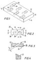
- FIG. 1 An exemplary substrate 10 is depicted in FIG. 1.
- Surface 12 is arbitrarily designated as the hot surface, while surface 14 is designated as the cold surface.
- Passage holes 16 extend throughout hole length section 18 (shown in phantom), exiting from the cold surface at hole bottom 19 (also shown in phantom).
- the distance between the hot surface and the cold surface is usually equivalent to the thickness of the substrate, and is designated as dimension "x" in FIG. 1.
- This distance is usually in the range of about 20 mils to about 2000 mils, and most often, in the range of about 50 mils to about 200 mils.
- the average diameter of the holes is typically in the range of about 10 mils to about 100 mils. In some embodiments, the diameter is in the range of about 15 mils to about 50 mils.
- the holes are usually situated at an angle, e.g., inclined at an angle of at least about 10 degrees to about 60 degrees, relative to the horizontal surface of the substrate.
- the angle is in the range of about 20 degrees to about 45 degrees.
- the particular angle of the holes is of course determined by the shape of the component; its cooling requirements; and empirical observations (and/or computer-modeling results) of air flow patterns through and across sample substrates.
- the present invention is thought to be applicable for the full range of hole inclination stated above.
- the depth of the passage hole (i.e., the "length" of a hole when it is situated at an angle) is usually in the range of about 20 mils to about 4000 mils. This range takes into account the relevant dimension of the exit site, discussed below. Typically, there are about 5 to about 200 holes per square-inch of the outer surface. In the case of an engine part such as a turbine combustion chamber, the density is usually about 40 to about 80 holes per square-inch.
- the present invention is directed to any number of passage holes.
- it can be used to improve the cooling effectiveness of a large array of holes (as found in a combustor liner); a row of holes; any random pattern or group of holes, or a single hole.
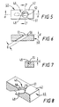
- FIG. 2 depicts a single passage hole 26 of the prior art.
- the top view depicts a hot surface 22 of substrate 20.
- the coolant steam would enter the hole at an entry site 30 (shown in phantom), and travel through hole length section 28, exiting at exit site 32.
- the area of the opening at the exit site will sometimes be referred to herein as the "penetration area", i.e., the planar area of the opening as viewed in a direction perpendicular to the surface.
- the penetration area would be the area of element 32.
- FIG. 3 shows the typical inclination of a passage hole (which originates at cold surface 24, and has a diameter "D") in a turbine engine component although the inclination can vary substantially, as discussed previously.
- FIG. 4 is another cross-sectional view which shows the typical shape of hole 26 at surface 22.
- the exiting coolant stream remain in contact with as much of hot surface 22 as possible.
- the stream sometimes has a tendency to separate from the surface immediately - especially under the high blowing ratios mentioned above, and at high inclination angles for the passage holes, e.g., greater than about 30 degrees relative to the horizontal surface of the substrate. If the concentration of coolant at the surface is insufficient, the part may become damaged due to excessive temperature-exposure.
- FIGS. 5-8 represent one embodiment of the present invention, in which the coolant stream has been disrupted.
- the exit site of hole 46 at hot surface 42 has been modified.
- the "exit site” is defined as the portion of the passage hole which borders the hot surface, and can be in the form of a crater, depression, or cavity for example.
- the exit site can be described with two parameters. First the depth of this portion of the passage hole usually constitutes about 10% to about 5001/G of the hole diameter, and in preferred embodiments, is about 201/G to about 100% of the hole diameter. Second, the planar area of the exit site (element 51 for FIG.
- the planar area of the exit site is usually in the range of about 200% to about 400% of the penetration area.
- the present invention is based in large part on the unexpected discovery that a rather sudden disruption of the flow of coolant results in the coolant stream contacting a greater area of the hot surface, leading to greater cooling effectiveness.
- the disruption is effected by maintaining a substantially uniform cross-sectional area for passage hole 46 (having a diameter "D") through the bulk of substrate 40, but enlarging the cross-sectional area of the passage hole at exit site 5 1.
- the exit site can be in the form of a crater, having a depth ("d"), and a sidewall 56 (substantially cylindrical in this embodiment) which is substantially vertical to the substrate surface.
- the central portion of the bottom of the crater opens into passage hole length section 48, continuing onto the cold surface (not shown).
- the required size of the modified section of the hole (i.e., the crater) relative to the remainder of the hole (i.e., the unchanged section) is not certain, since it appears that any enlargement according to the dimensions set forth above, may be beneficial in providing a source of disruption to the coolant flow.
- the depth of the crater would usually be about 5 mils to about 100 mils, and preferably, about 10 mils to about 30 mils.
- the passage hole itself can be prepared by a variety of techniques, such as laser drilling.
- a crater like tat depicted in the FIGS. 4-7 could also be formed by various well-known techniques, e.g., conventional machining, electrical discharge machining, or water jet drilling.
- the exit site e.g., the crater
- the depth should be less than about 50% of the length of the passage hole.
- the exit site has a depth which is less than about 35% of the length of the passage hole. The shallow depth of the exit site, relative to the length of the passage hole, tends to readily allow the coolant stream to move at its full force through the hole until it hits the obstruction. Such a disruption in coolant flow provides the advantages discussed herein.
- the axis (or centerline) of the passage hole is out of alignment with the axis of the exit site.
- This intended misalignment provides the desired type of disruption for the coolant flow, as opposed to simply diffusing the coolant flow, or merely directing the flow in a slightly different direction. The misalignment is often substantial.
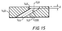
- FIG. 15, which is a substantially identical enlargement of FIG. 6, provides a helpful illustration regarding the relative, misaligned positions of the passage hole and an exit site, here in the form of a crater.
- Substrate 140 includes passage hole 142, which contains axis 144 through its approximate center (lengthwise).
- the passage hole terminates at crater 146, which contains axis 148 through the approximate center or depth of its length, i.e., its depth "d".
- the angle 150 between passage hole axis 144 and a lower extension of crater axis 148 is preferably at least about 20 degrees, and more preferably, at least about 30 degrees.
- FIG. 8 is another cross-sectional view of a portion of the modified passage hole 46 depicted in FIGS. 5-7.
- Hole length section 48 terminates at the rounded-crater 51 which serves as the exit site.
- a horizontal ledge 58 (which need not be present in all embodiments) is situated at the junction of hole section 4.8 with sidewall 56.
- sidewall 56 need not be substantially perpendicular to surface 42.
- the sidewall could be inclined in one direction or the other relative to the perpendicular position.
- the angle of the sidewall relative to surface 42 (or to horizontal ledge 58) could be as low as about 30 degrees, and as high as about 120 degrees.
- those skilled in the art can perform simulated or actual flow tests to determine the effect of a particular angle of inclination on coolant flow relative to surface 42.
- the sidewall does not have to be flat or smooth in some embodiments.
- the sidewall surface may be fairly irregular. The embodiment illustrated by FIG. 11 and discussed below usually includes this characteristic for the sidewall surface.
- Formation of an exit site in a substrate for the present invention can be carried out by a variety of processes, e.g., typical metalworking procedures for a metal-based substrate. Drilling, shaping, and machining techniques could be utilized to shape the holes according to specification. For an array of holes, these processes would sometimes be carded out with the aid of a computer, e.g., by a robotic system.
- the desired exit geometry of the hole could be obtained by placing a cover plate on the high-temperature surface of the substrate.
- the cover plate would have a lower surface planar with the substrate surface , i.e., adapted for attachment thereto. It would contain holes aligned with the passage holes in the substrate, having the dimensions of the desired exit site. In most embodiments, the thickness of the plate would be substantially equal to the depth of the exit site.
- the plate could be attached to the substrate by any technique appropriate for the end use of the substrate. Mechanical means such as bolting, welding, brazing, diffusion bonding, and the like, could be used in some instances, while an adhesive might be used in other embodiments.
- the resulting article would be similar in structure to that of FIGS. 6-8. The article would also be similar to that of FIGS. 9 and 10 (discussed below), if one were to view top layer 64 as a cover plate.
- the exit site can be formed by the application of a layer of material on top of the high-temperature surface of the substrate.
- the material is one suitable for use at high temperature, such as the TBC coating described previously. It is often ceramic-based.
- this top-layer material could be a synthetic polymer, such as an epoxy resin or a phenolic. These embodiments would be suitable for lower-temperature end uses, e.g., below about 400°C.
- FIG. 9 depicts one, non-limiting example of this embodiment in which top layer 64 lies over the hot surface 62 of substrate 60.
- Layer 64 includes an opening or "crater" which serves as the exit site 72 of passage hole 68.
- FIG. 10 is a cross-sectional view of FIG. 9 through lines 10-10, further illustrating one possible shape for the exit site. Although this figure depicts the presence of horizontal ledge 78, the ledge may have a smaller length than shown, or may be omitted, if sidewall 76 is formed in a manner which permits it to be situated closer to the uppermost edge of passage hole 68.
- the exit site 72 has a depth "d" (which in this embodiment is substantially identical to the height of sidewall 76) similar to that for previous embodiments, i.e., according to the dimensions set forth previously.
- sidewall 76 need not be substantially perpendicular to surface 62 and ledge 78.
- the sidewall could be inclined in one direction or the other relative to the perpendicular position, e.g., at an angle as low as about -60 degrees or as high as about +30 degrees relative to the perpendicular position, where a negative angle is defined as an inclination of the top of the sidewall inwardly toward the center of the crater, and a positive angle is of course an inclination in the opposite direction.
- various coolant flow tests can be employed to determine the most appropriate position for the sidewall.
- the exit site or crater may be aligned with the "upstream" edge of the passage hole (i.e., the edge closest to the coolant stream source), or the "downstream” edge of the passage hole.
- the crater does not have to be aligned with either edge, and can even extend beyond the edge of the passage hole. Coolant flow tests could again be used to determine the most appropriate configuration.
- Layer 64 could be comprised of materials which would typically constitute a TBC (by itself), a bond coat (by itself) for the TBC, or a TBC applied over a bond coat
- TBC system This two-coating structure is often referred to as a "TBC system".
- TBC systems protect metal-based substrates (or other types of substrates) and effectively raise the practical operating temperature of articles which incorporate those substrates, like aircraft engines.
- the bond layer for a metal substrate which is often very important for improving the adhesion between the substrate and the TBC, is usually formed from a material like "McrA1Y", where "M” represents a metal like iron, nickel, or cobalt.
- the bond coating may be applied by a variety of conventional techniques, such as PVD, plasma spray (e.g., air plasma), CVD, or combinations of plasma spray and CVD) techniques.
- zirconia-based embraces ceramic materials which contain at least about 75% zirconia.
- Zirconia is a well-known compound for barrier coatings, and is described, for example, in Kirk-Othmer's Encyclopedia of Chemical Technology , 3rd Edition, V. 24, pp. 882-883 (1984).
- the zirconia is chemically stabilized by being blended with a material such as yttrium oxide, calcium oxide, magnesium oxide, cerium oxide, scandium oxide, or mixtures of any of those materials.
- zirconia can be blended with about 1% by weight to about 20% by weight yttrium oxide (based on their combined weight), and preferably, from about 3%-10% yttrium oxide.
- the bond coat When the substrate is a metal-based component of a gas turbine engine, the bond coat usually has a thickness in the range of about 1 mil to about 10 mils, and preferably, in the range of about 3 mils to about 7 mils, while the TBC itself has a thickness in the range of about 5 mils to about 100 mils, and preferably, in the range of about 10 mils to about 40 mils.
- top layer 64 in the embodiments of FIGS. 9 and 10 is a TBC system, it will usually have dimensions within the combined ranges for the bond coat and the TBC. If either the bond coat or the TBC is used individually to form layer 64, each will be applied to a thickness in the range of that used for the two-part TBC system. As described previously, coolant flow behavior will dictate the most appropriate thickness of layer 64 (and consequently, the depth of exit site 72).
- the cooling passage holes can be formed in a top layer like layer 64 of FIG. 9 by a variety of techniques. Non-limiting examples include laser drilling of the holes, as well as conventional drilling and water jet drilling. When the top layer is formed of a synthetic or plastic type material, the holes could sometimes be prepared by photolithographic techniques, e.g., patterning and etching.
- a hole and terminating exit site Eke that featured in FIG. 9 is formed by the general technique taught in United States patent application serial number 08/758,328.
- the primary objective of the invention disclosed in that patent application is to temporarily protect a passage hole in a substrate from being obstructed by coatings applied over the substrate.
- the use some embodiments of that invention also results in an exit site for the passage hole which effectively disrupts the flow of a coolant stream, as required by the present invention.
- hole 68 in FIG. 9 would first be filled and covered with a curable masking material, prior to the formation of layer 64.
- the masking material (maskant) would form a protrusion over the hole.
- at least one coating is applied over the entire substrate and maskant, forming layer 64.
- the coatings do not substantially adhere to the protrusion.
- This discovery represents a particularly advantageous characteristic, since the exposed protrusions and the underlying remainder of maskant are relatively easy to remove. Subsequent removal of the maskant uncovers the passage hole, allowing unobstructed coolant flow.
- the geometry of exit site 72 after removal of the maskant results in the coolant stream contacting a greater area of the high-temperature surface (i.e., at this point the top surface 66 of layer 64), as described in the present application.
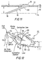
- FIG. 11 provides a cross-sectional illustration of the placement of a maskant for protecting a passage hole while also forming the necessary exit site-geometry of the present invention.
- the cured maskant 100 fills up and covers hole 90 which extends through substrate 80.
- the substrate includes coating layers 82 and 84.
- layers 82 and 84 are usually a bond coat and a TBC, as discussed previously.
- the maskant (or a precursor material) can be extruded through the hole from a hole entrance 98 on a cold surface 94, exiting the hole at hot surface 92, forming protrusion 96.
- the extrusion can be carried out by applying a layer of maskant material over cold surface 94, and then forming a pressure differential between the cold surface and hot surface 92, which will cause the maskant material to move through the hole and out to the hot surface.
- the maskant forms a protrusion on the hot surface, and the protrusion is often in the general shape of an elliptical dome.
- the maskant can comprise a wide variety of thermosetting or thermoplastic materials, such as epoxy resins, alkyd resins, phenolic resins, acrylic resins, thermoplastic polyesters, polyamides, polyolefins, styrene-based resins, and copolymers or mixtures of the thermoplastic materials.
- thermosetting or thermoplastic materials such as epoxy resins, alkyd resins, phenolic resins, acrylic resins, thermoplastic polyesters, polyamides, polyolefins, styrene-based resins, and copolymers or mixtures of the thermoplastic materials.
- thermoplastics refers generally to the cooling down and hardening of the material, as those skilled in the polymer arts understand.
- the resins are usually used in conjunction with at least one filler, plasticizer, or liquid crystal material.
- the overall material exhibits a substantially non-Newtonian flow characteristic, e.g., a Bingharn solid characteristic, which serves to ensure the formation of the protrusions.
- the maskant is removed to uncover the passage holes. As described in United States S.N. 08/758,328, removal can be effected by a variety of techniques, such as pyrolysis or the use of solvents.
- the resulting exit site geometry within the top layer coatings improves the cooling effectiveness of a coolant stream which moves through the passage hole and along hot surface 64.
- FIG. 12 is a general illustration of a section 110 of one type of turbine engine which could incorporate the present invention.
- Air supplied from a compressor moves through passage 112 and into combustion chamber 116.
- the main portion of the air is directed into combustion zone 117, along with fuel which originates at fuel source 114.
- the fuel and air are mixed and ignited in the combustion zone.
- separate streams of air are directed through liner passageways 118 and 120, along the cold sides 122, 123 of the combustor liner.
- the coolant air stream enters combustion zone 117 through passage holes 126 in combustor liner 128, which represents a "substrate" in the context of the present- invention.
- the coolant flow exits the substrate on the interior of the combustion zone, i.e., along the hot sides 124, 125 of the combustor liner.
- the geometry of the exit site of each of these passage holes is described in the previous figures. According to this invention, the disrupted coolant flow contacts a greater portion of hot sides 124, 125 than in those instances in which conventional passage holes are utilized. Greater cooling effectiveness of the combustor liner is thereby achieved.
- Another embodiment of this invention is directed to an article, comprising:
- the present invention is useful for modifying cooling channels in other types of engine components, e.g., turbine blades, vanes, and endwalls. Moreover, the invention could be utilized for modifying the flow of air or other gasses through passageways in any other type of structure.
- Substrate A was aluminum, and had a thickness of about 400 mils. It included six passage holes having a length of about 1200 mils and a diameter of about 100 mils. The holes were spaced 6.5 hole-diameters apart. The were inclined at an angle of about 20 degrees relative to the top surface of the substrate, which will arbitrarily be referred to herein as the "hot surface".
- the passage holes had a conventional shape, i.e., there was no modification of hole shape.
- Substrate B was also formed of aluminum.
- the main body of the substrate had the same thickness and the same types of passage holes (six of them) as substrate A.
- a plate containing six passage holes perpendicular to the plate surface was placed over the substrate, face-to-face.
- the plate had a thickness of 75 mils, and six of the circular holes in the plate were aligned with passage holes in the main substrate. This resulted in the formation of a modified exit site for the passage holes, similar in geometry to that depicted in FIGS. 9-10.
- the characterization technique employed Planar Laser Induced Fluorescence (PLIF), which is described in United States S.N. 08/839,114. This technique provides a reliable measurement of "near-wall" fluid concentration, measuring the concentration of cooling fluid along the dimensions of a given surface.
- PLIF Planar Laser Induced Fluorescence
- This technique provides a reliable measurement of "near-wall" fluid concentration, measuring the concentration of cooling fluid along the dimensions of a given surface.
- the orientation of a cooling model was first adjusted so that a light sheet (provided by a laser) was parallel to the cooling model.
- a test tunnel having a hot gas simulation flow and a cooling simulation flow both water in this instance was then uniformly filled with the water, which contained a fluorescent dye.
- the cooling simulation flow was passed through the passage holes of interest.
- the blowing ratio was varied from about 0.5 to 5.7.
- the cooling simulation flow image was then mathematically divided by the combined hot gas flow and cooling flow image, using a digital image processing system which allowed the measurement of both time average and instantaneous cooling fluid concentration at any location above the cooling model. The same technique was used for each substrate. Cooling performance was measured over six different blowing ratios.
- the Reynolds number (a nondimensional flow parameter) of the air flowing through the cooling holes was about 1000. (The Reynolds number would increase as the blowing ratio is increased).
- the ratio of the coolant density to the mainstream density was approximately 1.0.
- a scale from 0% to 100% was used to represent the range of cooling effectiveness. A value of 0% indicated that no cooling fluid was present at a given portion of the surface. The scale progressed to a value of 100%, with increasing percentages representing a greater concentration of cooling fluid at the surface of interest.
- the measurements for substrate A were taken over the following blowing ratios: 0.5, 0.8, 1.7, 3.3, 4.4, and 5.7.
- the cooling effectiveness was about 20%.
- the blowing ratio was increased to 1.7, no improvement was seen in cooling effectiveness. In fact, it decreased to about 5%.
- Some improvement was evident at a blowing ratio of 3.3, but the cooling effectiveness was had not reached the level for a blowing ratio of 0.5. Further improvement was seen at the blowing ratios of 4.4 and 5.7, with average cooling effectiveness values in the approximate range of those for the 0.5 ratio.
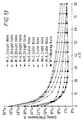
- Example 1 While the experiments performed in Example 1 are thought to provide a reliable prediction of cooling effectiveness in the case of air coolant (based on water coolant effectiveness), an additional experiment was undertaken, using air flow.
- Substrates C and D were formed of stainless steel, but were otherwise similar to those used in Example 1. The substrate thickness was 0.4 inch.
- Substrate C included five holes arranged in a row and having a conventional shape.
- Substrate D also included five holes in a row, but had a modified exit site geometry according to the present invention. The modification was achieved in the manner of substrate B in Example 1, i.e., with a plate situated on top of the main body of the substrate, having five circular plate holes aligned with the substrate holes. As in the case of substrate B, the crater (exit site) was aligned with the remainder of the passage hole as depicted in FIGS. 9 and 10.
- the substrate formed part of one wall of a small metal wind tunnel.
- the distance between the holes was 6.5 hole diameters, and the cooling hole diameter in each instance was about 0. 1 inch.
- the crater depth was 0.075 inch, while the crater diameter was 0.235 inch.
- the cooling holes were inclined at an angle of 20 degrees relative to the horizontal position.
- Cool air (approximately room temperature and pressure) flowed through the cooling holes, while hot air (at approximately 600°F (315°C) and room pressure) flowed through the wind tunnel.
- the wall of the wind tunnel downstream of the cooling holes was insulated. It also was fitted with a multitude of thermocouples to measure wall temperature.
- the ratio of the coolant density to the mainstream density was approximately 1.9, which is similar to that found in a turbine engine combustion zone.
- the Reynolds number of the air flowing through the cooling holes was also close to that found in the combustion zone of a combustor, i.e., about 10,000.
- FIG. 13 The figure depicts cooling effectiveness on the y-axis, as a function of the distance downstream (the x-axis, in hole diameter-units) of the edge of the cooling holes. The effectiveness is being measured along the surface being cooled and along the center-line of the middle hole of the row, in the direction of the mainstream flow along the surface. Clearly, cooling effectiveness is greatly enhanced with the modified passage holes of the present invention. For example, in the case of a blowing ratio of 1, higher effectiveness values are seen along the entire surface.
- film cooling performance was measured for a substrate in which the exit site geometry was modified by the use of a thermal barrier coating (TBC).
- TBC thermal barrier coating
- the comparative sample is the substrate prior to application of the TBC. It will be designated as sample E, while, the TBC-covered substrate will be designated as sample F.
- the substrate was a nickel-based superalloy, and had a thickness of about 80 mils.
- the substrate was a 3 inch x 3 inch square array of 371 holes, formed by laser drilling. The length of the holes was about 240 mils, and the hole diameter was about 22 mils.
- the holes were spaced 5.9 hole-diameters apart, and were inclined at an angle of about 20 degrees relative to the top surface of the substrate, which will arbitrarily be referred to herein as the "hot surface".
- the passage holes prior to application of the TBC system, had a conventional shape, i.e., without any modification.
- the exit site geometry for the passage holes of sample F was formed according to the process described above for United States S.N. 08/758,328.
- a 2-part epoxy material was extruded through the holes from the upstream side of the substrate (i.e., the surface opposite the hot surface, and sometimes referred to as the "cold" surface), forming the protrusion on the hot surface, similar to that depicted in FIG. 11.
- Afler the surface was grit-blasted, a bond coat layer formed of NiCrAlY was applied by air-plasma spray, to a thickness of 5 mils.
- a TBC based on yttria-stabilized zirconia was then also applied by air-plasma spray, to a thickness of 10 mils.
- the epoxy material was then removed pyrolytically in an oven at elevated temperature.
- the resul i g exit site for the passage holes included a crater somewhat oval in shape, having a penetration area width of 58 mils, and a crater area-diameter (i.e., the TBC opening, perpendicular to the stream-wise direction) of 47 mils.
- the sidewalls of the exit site were somewhat curved and uneven, as would be the case when the masking material in the structure of FIG. 11 is removed.
- Cooling effectiveness was measured (before and after application of the TBC system) by the PLIF technique described for Example 1, wherein the cooling simulation flow was passed through the passage holes of interest. Water was used as the coolant.
- a blowing ratio having a value (M) of 4 was tested, which is representative of combustion liner conditions.
- FIG. 14 is based on the results for these tests, and represents cooling effectiveness as a function of stream-wise position.
- Two curves are represented in the figure, representing samples E and F at the blowing ratio of 4.
- the y-axis represents film cooling effectiveness
- the x-axis represents the x/D distance within the large array of passage holes, wherein the value of 0 for x/D is the first row of holes. (The testing technique permitted the generation of data on the central-portion of the array.).
- each row of holes in a large array involves the further addition of coolant stream material, and the cooling effectiveness values are increased with downstream progression (in contrast to Examples 1 and 2).
- a large increase in cooling effectiveness for the sample with the modified exit hole geometry was again evident with as much as a two-fold improvement.
Landscapes
- Engineering & Computer Science (AREA)
- Mechanical Engineering (AREA)
- General Engineering & Computer Science (AREA)
- Chemical & Material Sciences (AREA)
- Combustion & Propulsion (AREA)
- Materials Engineering (AREA)
- Turbine Rotor Nozzle Sealing (AREA)
- Coating By Spraying Or Casting (AREA)
Applications Claiming Priority (2)
| Application Number | Priority Date | Filing Date | Title |
|---|---|---|---|
| US285966 | 1999-04-05 | ||
| US09/285,966 US6383602B1 (en) | 1996-12-23 | 1999-04-05 | Method for improving the cooling effectiveness of a gaseous coolant stream which flows through a substrate, and related articles of manufacture |
Publications (2)
| Publication Number | Publication Date |
|---|---|
| EP1043480A2 true EP1043480A2 (fr) | 2000-10-11 |
| EP1043480A3 EP1043480A3 (fr) | 2002-10-16 |
Family
ID=23096455
Family Applications (1)
| Application Number | Title | Priority Date | Filing Date |
|---|---|---|---|
| EP00302884A Withdrawn EP1043480A3 (fr) | 1999-04-05 | 2000-04-05 | Refroidissement à pellicule des parois chaudes |
Country Status (5)
| Country | Link |
|---|---|
| US (1) | US6383602B1 (fr) |
| EP (1) | EP1043480A3 (fr) |
| JP (1) | JP2000310464A (fr) |
| CN (1) | CN1272593A (fr) |
| SG (1) | SG90121A1 (fr) |
Cited By (25)
| Publication number | Priority date | Publication date | Assignee | Title |
|---|---|---|---|---|
| EP1091090A2 (fr) | 1999-10-04 | 2001-04-11 | General Electric Company | Méthode d'amélioration d'efficacité de refroidissement d'une pellicule de gaz et articles associés |
| WO2002032614A1 (fr) | 2000-10-18 | 2002-04-25 | Chromalloy Gas Turbine Corporation | Procede de percage de trous dans une piece a travailler metallique possedant un revetement d'isolement thermique |
| DE10244199A1 (de) * | 2002-09-23 | 2004-04-01 | Alstom (Switzerland) Ltd. | Einbringung eines Sekundärfluids in eine transsonische Primärströmung |
| EP1262631A3 (fr) * | 2001-05-21 | 2004-05-26 | United Technologies Corporation | Aube de turbine refroidié par couche d'air |
| EP1291142A3 (fr) * | 2001-08-27 | 2004-07-28 | General Electric Company | Procédé ainsi que plaquettes de blocage pour arrêter des impactes de jets d'eau sur une paroi postérieure |
| EP1515090A1 (fr) * | 2003-09-10 | 2005-03-16 | General Electric Company | Chambre de combustion avec revêtement épais |
| EP1712739A1 (fr) * | 2005-04-12 | 2006-10-18 | Siemens Aktiengesellschaft | Elément avec trou de refroidissement par film |
| EP1892375A1 (fr) * | 2006-08-23 | 2008-02-27 | Siemens Aktiengesellschaft | Disque de rotor d'un moteur à turbine avec passage de refroidissement |
| WO2008137201A1 (fr) * | 2007-05-01 | 2008-11-13 | General Electric Company | Trous de refroidissement pour chemise de chambre de combustion de turbine à gaz ayant un diamètre non uniforme au travers |
| EP1997581A1 (fr) | 2007-05-29 | 2008-12-03 | Metem Corporation | Procédé et dispositif pour le fraisage de métaux revêtus d'une barrière thermique |
| EP1635119A3 (fr) * | 2004-09-09 | 2009-06-17 | United Technologies Corporation | Composants refroidis pour turbine à gaz |
| EP2216509A1 (fr) * | 2009-02-04 | 2010-08-11 | Siemens Aktiengesellschaft | Composant de turbine doté d'une couche de protection pouvant être enlevée simplement, ensemble de composants de turbines, turbine et procédé de protection d'un composant de turbine |
| WO2012021194A3 (fr) * | 2010-06-11 | 2012-04-05 | Siemens Energy, Inc. | Paroi constitutive ayant des sections de diffusion pour le refroidissement dans un moteur de turbine |
| WO2012057908A3 (fr) * | 2010-10-29 | 2013-09-12 | General Electric Company | Substrat comportant des trous de refroidissement façonnés et procédés de fabrication |
| WO2014099161A1 (fr) | 2012-12-20 | 2014-06-26 | United Technologies Corporation | Fermeture de trous de refroidissement avec un agent de remplissage |
| US9028207B2 (en) | 2010-09-23 | 2015-05-12 | Siemens Energy, Inc. | Cooled component wall in a turbine engine |
| US9664111B2 (en) | 2012-12-19 | 2017-05-30 | United Technologies Corporation | Closure of cooling holes with a filing agent |
| EP2617940A3 (fr) * | 2012-01-18 | 2017-07-05 | Rolls-Royce plc | Procédé de scellement de trous de refroidissement d'un profi d'une aube de turbine |
| WO2017148916A1 (fr) * | 2016-03-02 | 2017-09-08 | Siemens Aktiengesellschaft | Système de couches avec élimination de la couche située autour des trous pour air de refroidissement d'aubes de turbine |
| US9771804B2 (en) | 2011-08-08 | 2017-09-26 | Siemens Aktiengesellschaft | Film cooling of turbine blades or vanes |
| EP2390465A3 (fr) * | 2010-05-28 | 2017-12-20 | General Electric Company | Composant de turbine à gaz avec des trous de refroidissement par film d'air ayant forme de chevron et procédés relatifs à celui-ci |
| EP3441569A1 (fr) * | 2017-08-07 | 2019-02-13 | United Technologies Corporation | Procédé de production d'un dispositif, sortie de buse et dispositif de nettoyage au laser d'un revêtement |
| US10239157B2 (en) | 2016-04-06 | 2019-03-26 | General Electric Company | Additive machine utilizing rotational build surface |
| EP2554792B1 (fr) * | 2010-03-24 | 2020-10-07 | Kawasaki Jukogyo Kabushiki Kaisha | Structure de refroidissement par film à double jet |
| DE102020007518A1 (de) | 2020-12-09 | 2022-06-09 | Svetlana Beck | Verfahren zum Erreichen von hohen Gastemperaturen unter Verwendung von Zentrifugalkraft |
Families Citing this family (98)
| Publication number | Priority date | Publication date | Assignee | Title |
|---|---|---|---|---|
| US6984100B2 (en) * | 2003-06-30 | 2006-01-10 | General Electric Company | Component and turbine assembly with film cooling |
| US20040265488A1 (en) * | 2003-06-30 | 2004-12-30 | General Electric Company | Method for forming a flow director on a hot gas path component |
| US20050220618A1 (en) * | 2004-03-31 | 2005-10-06 | General Electric Company | Counter-bored film-cooling holes and related method |
| US20060016191A1 (en) * | 2004-07-23 | 2006-01-26 | Honeywell International Inc. | Combined effusion and thick TBC cooling method |
| JP4752841B2 (ja) * | 2005-11-01 | 2011-08-17 | 株式会社Ihi | タービン部品 |
| US7351036B2 (en) * | 2005-12-02 | 2008-04-01 | Siemens Power Generation, Inc. | Turbine airfoil cooling system with elbowed, diffusion film cooling hole |
| US20080005903A1 (en) † | 2006-07-05 | 2008-01-10 | United Technologies Corporation | External datum system and film hole positioning using core locating holes |
| US7553534B2 (en) * | 2006-08-29 | 2009-06-30 | General Electric Company | Film cooled slotted wall and method of making the same |
| US7820267B2 (en) * | 2007-08-20 | 2010-10-26 | Honeywell International Inc. | Percussion drilled shaped through hole and method of forming |
| US7980820B2 (en) * | 2007-08-27 | 2011-07-19 | United Technologies Corporation | Turbine engine blade cooling |
| FR2927356B1 (fr) * | 2008-02-07 | 2013-03-01 | Snecma | Aubes pour roue a aubes de turbomachine avec rainure pour le refroidissement. |
| US20100011770A1 (en) * | 2008-07-21 | 2010-01-21 | Ronald James Chila | Gas Turbine Premixer with Cratered Fuel Injection Sites |
| US8397511B2 (en) * | 2009-05-19 | 2013-03-19 | General Electric Company | System and method for cooling a wall of a gas turbine combustor |
| MX341495B (es) | 2010-01-14 | 2016-08-23 | Neptco Inc * | Componentes de pala de rotor de turbina eolica y metodos para la fabricacion de los mismos. |
| US10137542B2 (en) | 2010-01-14 | 2018-11-27 | Senvion Gmbh | Wind turbine rotor blade components and machine for making same |
| US8608443B2 (en) | 2010-06-11 | 2013-12-17 | Siemens Energy, Inc. | Film cooled component wall in a turbine engine |
| US8672613B2 (en) | 2010-08-31 | 2014-03-18 | General Electric Company | Components with conformal curved film holes and methods of manufacture |
| US9696035B2 (en) | 2010-10-29 | 2017-07-04 | General Electric Company | Method of forming a cooling hole by laser drilling |
| US8572981B2 (en) * | 2010-11-08 | 2013-11-05 | General Electric Company | Self-oscillating fuel injection jets |
| US9249491B2 (en) | 2010-11-10 | 2016-02-02 | General Electric Company | Components with re-entrant shaped cooling channels and methods of manufacture |
| US8673397B2 (en) | 2010-11-10 | 2014-03-18 | General Electric Company | Methods of fabricating and coating a component |
| US8753071B2 (en) | 2010-12-22 | 2014-06-17 | General Electric Company | Cooling channel systems for high-temperature components covered by coatings, and related processes |
| US20120164376A1 (en) * | 2010-12-23 | 2012-06-28 | General Electric Company | Method of modifying a substrate for passage hole formation therein, and related articles |
| US9157328B2 (en) | 2010-12-24 | 2015-10-13 | Rolls-Royce North American Technologies, Inc. | Cooled gas turbine engine component |
| US8601691B2 (en) | 2011-04-27 | 2013-12-10 | General Electric Company | Component and methods of fabricating a coated component using multiple types of fillers |
| US9327384B2 (en) | 2011-06-24 | 2016-05-03 | General Electric Company | Components with cooling channels and methods of manufacture |
| US9216491B2 (en) | 2011-06-24 | 2015-12-22 | General Electric Company | Components with cooling channels and methods of manufacture |
| US9206696B2 (en) | 2011-08-16 | 2015-12-08 | General Electric Company | Components with cooling channels and methods of manufacture |
| US9249672B2 (en) | 2011-09-23 | 2016-02-02 | General Electric Company | Components with cooling channels and methods of manufacture |
| US20130086784A1 (en) | 2011-10-06 | 2013-04-11 | General Electric Company | Repair methods for cooled components |
| US9249670B2 (en) | 2011-12-15 | 2016-02-02 | General Electric Company | Components with microchannel cooling |
| US9133724B2 (en) | 2012-01-09 | 2015-09-15 | General Electric Company | Turbomachine component including a cover plate |
| US9011078B2 (en) | 2012-01-09 | 2015-04-21 | General Electric Company | Turbine vane seal carrier with slots for cooling and assembly |
| US8944751B2 (en) | 2012-01-09 | 2015-02-03 | General Electric Company | Turbine nozzle cooling assembly |
| US8864445B2 (en) | 2012-01-09 | 2014-10-21 | General Electric Company | Turbine nozzle assembly methods |
| US9011079B2 (en) | 2012-01-09 | 2015-04-21 | General Electric Company | Turbine nozzle compartmentalized cooling system |
| US9039350B2 (en) | 2012-01-09 | 2015-05-26 | General Electric Company | Impingement cooling system for use with contoured surfaces |
| CN103244196B (zh) * | 2012-02-08 | 2015-04-22 | 中国科学院工程热物理研究所 | 一种离散气膜冷却孔型 |
| CH706090A1 (de) * | 2012-02-17 | 2013-08-30 | Alstom Technology Ltd | Verfahren zum Herstellen eines oberflächennahen Kühlkanals in einem thermisch hoch beanspruchten Bauteil sowie Bauteil mit einem solchen Kanal. |
| US9435208B2 (en) | 2012-04-17 | 2016-09-06 | General Electric Company | Components with microchannel cooling |
| US9234438B2 (en) | 2012-05-04 | 2016-01-12 | Siemens Aktiengesellschaft | Turbine engine component wall having branched cooling passages |
| US9243503B2 (en) | 2012-05-23 | 2016-01-26 | General Electric Company | Components with microchannel cooled platforms and fillets and methods of manufacture |
| US9303517B2 (en) * | 2012-06-15 | 2016-04-05 | General Electric Company | Channel marker and related methods |
| DE102013109116A1 (de) | 2012-08-27 | 2014-03-27 | General Electric Company (N.D.Ges.D. Staates New York) | Bauteil mit Kühlkanälen und Verfahren zur Herstellung |
| US8974859B2 (en) | 2012-09-26 | 2015-03-10 | General Electric Company | Micro-channel coating deposition system and method for using the same |
| US9242294B2 (en) | 2012-09-27 | 2016-01-26 | General Electric Company | Methods of forming cooling channels using backstrike protection |
| US9238265B2 (en) | 2012-09-27 | 2016-01-19 | General Electric Company | Backstrike protection during machining of cooling features |
| US9200521B2 (en) | 2012-10-30 | 2015-12-01 | General Electric Company | Components with micro cooled coating layer and methods of manufacture |
| US9562436B2 (en) | 2012-10-30 | 2017-02-07 | General Electric Company | Components with micro cooled patterned coating layer and methods of manufacture |
| EP2733310A1 (fr) * | 2012-11-16 | 2014-05-21 | Siemens Aktiengesellschaft | Surface modifiée autour d'un trou |
| US9003657B2 (en) | 2012-12-18 | 2015-04-14 | General Electric Company | Components with porous metal cooling and methods of manufacture |
| WO2014137470A1 (fr) | 2013-03-05 | 2014-09-12 | Vandervaart Peter L | Agencement de composant pour moteur à turbine à gaz |
| WO2014163698A1 (fr) | 2013-03-07 | 2014-10-09 | Vandervaart Peter L | Pièce refroidie de turbine à gaz |
| CA2898822A1 (fr) | 2013-03-13 | 2014-10-09 | Rolls-Royce Corporation | Agencement de trou de refroidissement a tranchee pour une ailette composite a matrice ceramique |
| US9638057B2 (en) | 2013-03-14 | 2017-05-02 | Rolls-Royce North American Technologies, Inc. | Augmented cooling system |
| DE102013214487A1 (de) * | 2013-07-24 | 2015-01-29 | Rolls-Royce Deutschland Ltd & Co Kg | Brennkammerschindel einer Gasturbine |
| US9250188B2 (en) | 2013-09-10 | 2016-02-02 | General Electric Company | System and method for measuring cooling of a component |
| CN103452595A (zh) * | 2013-09-25 | 2013-12-18 | 青岛科技大学 | 一种提高冷却效率的新型气膜孔 |
| DE102013221227A1 (de) | 2013-10-18 | 2015-05-07 | Rolls-Royce Deutschland Ltd & Co Kg | Vorrichtung zur Kühlung einer Wandung eines Bauteils |
| US9278462B2 (en) | 2013-11-20 | 2016-03-08 | General Electric Company | Backstrike protection during machining of cooling features |
| US9476306B2 (en) | 2013-11-26 | 2016-10-25 | General Electric Company | Components with multi-layered cooling features and methods of manufacture |
| US10364684B2 (en) | 2014-05-29 | 2019-07-30 | General Electric Company | Fastback vorticor pin |
| CA2950011C (fr) | 2014-05-29 | 2020-01-28 | General Electric Company | Generateur de turbulence fastback |
| GB201419327D0 (en) | 2014-10-30 | 2014-12-17 | Rolls Royce Plc | A cooled component |
| US10233775B2 (en) | 2014-10-31 | 2019-03-19 | General Electric Company | Engine component for a gas turbine engine |
| US10280785B2 (en) | 2014-10-31 | 2019-05-07 | General Electric Company | Shroud assembly for a turbine engine |
| US10247011B2 (en) * | 2014-12-15 | 2019-04-02 | United Technologies Corporation | Gas turbine engine component with increased cooling capacity |
| US10132166B2 (en) | 2015-02-27 | 2018-11-20 | General Electric Company | Engine component |
| US10024169B2 (en) | 2015-02-27 | 2018-07-17 | General Electric Company | Engine component |
| US10208602B2 (en) * | 2015-04-27 | 2019-02-19 | United Technologies Corporation | Asymmetric diffuser opening for film cooling holes |
| FR3037107B1 (fr) * | 2015-06-03 | 2019-11-15 | Safran Aircraft Engines | Paroi annulaire de chambre de combustion a refroidissement optimise |
| US9970302B2 (en) * | 2015-06-15 | 2018-05-15 | General Electric Company | Hot gas path component trailing edge having near wall cooling features |
| US9938899B2 (en) | 2015-06-15 | 2018-04-10 | General Electric Company | Hot gas path component having cast-in features for near wall cooling |
| US9897006B2 (en) | 2015-06-15 | 2018-02-20 | General Electric Company | Hot gas path component cooling system having a particle collection chamber |
| US9828915B2 (en) | 2015-06-15 | 2017-11-28 | General Electric Company | Hot gas path component having near wall cooling features |
| CA2933884A1 (fr) * | 2015-06-30 | 2016-12-30 | Rolls-Royce Corporation | Tuile de combustor |
| US10392947B2 (en) | 2015-07-13 | 2019-08-27 | General Electric Company | Compositions and methods of attachment of thick environmental barrier coatings on CMC components |
| US10378444B2 (en) | 2015-08-19 | 2019-08-13 | General Electric Company | Engine component for a gas turbine engine |
| US11149646B2 (en) | 2015-09-02 | 2021-10-19 | General Electric Company | Piston ring assembly for a turbine engine |
| US10168051B2 (en) | 2015-09-02 | 2019-01-01 | General Electric Company | Combustor assembly for a turbine engine |
| US10197278B2 (en) | 2015-09-02 | 2019-02-05 | General Electric Company | Combustor assembly for a turbine engine |
| US9976746B2 (en) | 2015-09-02 | 2018-05-22 | General Electric Company | Combustor assembly for a turbine engine |
| US10161266B2 (en) | 2015-09-23 | 2018-12-25 | General Electric Company | Nozzle and nozzle assembly for gas turbine engine |
| US10563867B2 (en) | 2015-09-30 | 2020-02-18 | General Electric Company | CMC articles having small complex features for advanced film cooling |
| US20170234142A1 (en) * | 2016-02-17 | 2017-08-17 | General Electric Company | Rotor Blade Trailing Edge Cooling |
| US10100668B2 (en) * | 2016-02-24 | 2018-10-16 | General Electric Company | System and method of fabricating and repairing a gas turbine component |
| US10458251B2 (en) | 2016-04-15 | 2019-10-29 | General Electric Company | Airfoil cooling using non-line of sight holes |
| US20170306764A1 (en) * | 2016-04-26 | 2017-10-26 | General Electric Company | Airfoil for a turbine engine |
| US10247009B2 (en) * | 2016-05-24 | 2019-04-02 | General Electric Company | Cooling passage for gas turbine system rotor blade |
| US20180266687A1 (en) * | 2017-03-16 | 2018-09-20 | General Electric Company | Reducing film scrubbing in a combustor |
| US10465607B2 (en) | 2017-04-05 | 2019-11-05 | United Technologies Corporation | Method of manufacturing conductive film holes |
| US11402097B2 (en) | 2018-01-03 | 2022-08-02 | General Electric Company | Combustor assembly for a turbine engine |
| US10563519B2 (en) * | 2018-02-19 | 2020-02-18 | General Electric Company | Engine component with cooling hole |
| US11225707B2 (en) | 2019-08-13 | 2022-01-18 | General Electric Company | Protective shields for improved coating of turbine component cooling features |
| CN112901283B (zh) * | 2021-03-04 | 2022-04-22 | 西安交通大学 | 一种蝠鲼型仿生凸台和凹坑结构的多级抽吸气膜冷却孔结构 |
| US11629857B2 (en) * | 2021-03-31 | 2023-04-18 | General Electric Company | Combustor having a wake energizer |
| US11674686B2 (en) | 2021-05-11 | 2023-06-13 | Honeywell International Inc. | Coating occlusion resistant effusion cooling holes for gas turbine engine |
| CN114165811B (zh) * | 2021-10-20 | 2023-03-21 | 中国航发四川燃气涡轮研究院 | 自带冷却结构的射流套管 |
Family Cites Families (19)
| Publication number | Priority date | Publication date | Assignee | Title |
|---|---|---|---|---|
| GB2066372A (en) * | 1979-12-26 | 1981-07-08 | United Technologies Corp | Coolable wall element |
| GB2127105B (en) | 1982-09-16 | 1985-06-05 | Rolls Royce | Improvements in cooled gas turbine engine aerofoils |
| JPS6032903A (ja) * | 1983-08-01 | 1985-02-20 | Agency Of Ind Science & Technol | ガスタ−ビンの翼 |
| US4653983A (en) * | 1985-12-23 | 1987-03-31 | United Technologies Corporation | Cross-flow film cooling passages |
| US4669957A (en) * | 1985-12-23 | 1987-06-02 | United Technologies Corporation | Film coolant passage with swirl diffuser |
| US4743462A (en) * | 1986-07-14 | 1988-05-10 | United Technologies Corporation | Method for preventing closure of cooling holes in hollow, air cooled turbine engine components during application of a plasma spray coating |
| US4923371A (en) * | 1988-04-01 | 1990-05-08 | General Electric Company | Wall having cooling passage |
| GB2227965B (en) * | 1988-10-12 | 1993-02-10 | Rolls Royce Plc | Apparatus for drilling a shaped hole in a workpiece |
| US5039562A (en) | 1988-10-20 | 1991-08-13 | The United States Of America As Represented By The Secretary Of The Air Force | Method and apparatus for cooling high temperature ceramic turbine blade portions |
| GB2244673B (en) | 1990-06-05 | 1993-09-01 | Rolls Royce Plc | A perforated sheet and a method of making the same |
| US5281084A (en) | 1990-07-13 | 1994-01-25 | General Electric Company | Curved film cooling holes for gas turbine engine vanes |
| US5382133A (en) * | 1993-10-15 | 1995-01-17 | United Technologies Corporation | High coverage shaped diffuser film hole for thin walls |
| JPH07279612A (ja) | 1994-04-14 | 1995-10-27 | Mitsubishi Heavy Ind Ltd | 重質油焚き用ガスタービン冷却翼 |
| US5503529A (en) | 1994-12-08 | 1996-04-02 | General Electric Company | Turbine blade having angled ejection slot |
| US5902647A (en) * | 1996-12-03 | 1999-05-11 | General Electric Company | Method for protecting passage holes in a metal-based substrate from becoming obstructed, and related compositions |
| EP0851098A3 (fr) * | 1996-12-23 | 2000-09-13 | General Electric Company | Méthode pour améliorer l'effet des trous de refroidssement par pellicule |
| JPH1162504A (ja) * | 1997-08-13 | 1999-03-05 | Ishikawajima Harima Heavy Ind Co Ltd | タービン翼の二重壁冷却構造 |
| EP0945593B1 (fr) * | 1998-03-23 | 2003-05-07 | ALSTOM (Switzerland) Ltd | Trou de refroidissement pelliculaire |
| EP0992653A1 (fr) * | 1998-10-08 | 2000-04-12 | Abb Research Ltd. | Composants réfroidis par couche d'air avec perçages de refroidissement à section transversale triangulaire |
-
1999
- 1999-04-05 US US09/285,966 patent/US6383602B1/en not_active Expired - Fee Related
-
2000
- 2000-04-04 JP JP2000101648A patent/JP2000310464A/ja not_active Withdrawn
- 2000-04-05 CN CN00104969A patent/CN1272593A/zh active Pending
- 2000-04-05 EP EP00302884A patent/EP1043480A3/fr not_active Withdrawn
- 2000-04-05 SG SG200001927A patent/SG90121A1/en unknown
Cited By (41)
| Publication number | Priority date | Publication date | Assignee | Title |
|---|---|---|---|---|
| EP1091090A2 (fr) | 1999-10-04 | 2001-04-11 | General Electric Company | Méthode d'amélioration d'efficacité de refroidissement d'une pellicule de gaz et articles associés |
| EP1332016A4 (fr) * | 2000-10-18 | 2008-02-06 | Turbocombustor Technology Inc | Procede de percage de trous dans une piece a travailler metallique possedant un revetement d'isolement thermique |
| WO2002032614A1 (fr) | 2000-10-18 | 2002-04-25 | Chromalloy Gas Turbine Corporation | Procede de percage de trous dans une piece a travailler metallique possedant un revetement d'isolement thermique |
| EP1262631A3 (fr) * | 2001-05-21 | 2004-05-26 | United Technologies Corporation | Aube de turbine refroidié par couche d'air |
| US6932572B2 (en) | 2001-05-21 | 2005-08-23 | United Technologies Corporation | Film cooled article with improved temperature tolerance |
| EP1291142A3 (fr) * | 2001-08-27 | 2004-07-28 | General Electric Company | Procédé ainsi que plaquettes de blocage pour arrêter des impactes de jets d'eau sur une paroi postérieure |
| DE10244199A1 (de) * | 2002-09-23 | 2004-04-01 | Alstom (Switzerland) Ltd. | Einbringung eines Sekundärfluids in eine transsonische Primärströmung |
| EP1515090A1 (fr) * | 2003-09-10 | 2005-03-16 | General Electric Company | Chambre de combustion avec revêtement épais |
| EP1635119A3 (fr) * | 2004-09-09 | 2009-06-17 | United Technologies Corporation | Composants refroidis pour turbine à gaz |
| EP1712739A1 (fr) * | 2005-04-12 | 2006-10-18 | Siemens Aktiengesellschaft | Elément avec trou de refroidissement par film |
| WO2006108749A1 (fr) | 2005-04-12 | 2006-10-19 | Siemens Aktiengesellschaft | Composant a trou de refroidissement par film fluide |
| CN100582439C (zh) * | 2005-04-12 | 2010-01-20 | 西门子公司 | 带有气膜冷却孔的构件 |
| US8157526B2 (en) | 2005-04-12 | 2012-04-17 | Siemens Aktiengesellschaft | Component having a film cooling hole |
| EP2428646A1 (fr) * | 2005-04-12 | 2012-03-14 | Siemens Aktiengesellschaft | Composant à trous de refroidissement par film |
| EP2292898A1 (fr) * | 2005-04-12 | 2011-03-09 | Siemens Aktiengesellschaft | Elément avec trou de refroidissement par film |
| EP1892375A1 (fr) * | 2006-08-23 | 2008-02-27 | Siemens Aktiengesellschaft | Disque de rotor d'un moteur à turbine avec passage de refroidissement |
| WO2008022954A1 (fr) * | 2006-08-23 | 2008-02-28 | Siemens Aktiengesellschaft | Disque rotor de moteur à turbine comprenant un passage de refroidissement |
| US8348615B2 (en) | 2006-08-23 | 2013-01-08 | Siemens Aktiengesellschaft | Turbine engine rotor disc with cooling passage |
| WO2008137201A1 (fr) * | 2007-05-01 | 2008-11-13 | General Electric Company | Trous de refroidissement pour chemise de chambre de combustion de turbine à gaz ayant un diamètre non uniforme au travers |
| EP1997581A1 (fr) | 2007-05-29 | 2008-12-03 | Metem Corporation | Procédé et dispositif pour le fraisage de métaux revêtus d'une barrière thermique |
| US7992272B2 (en) | 2007-05-29 | 2011-08-09 | Metem Corporation | Method and apparatus for milling thermal barrier coated metals |
| US8177696B2 (en) | 2007-05-29 | 2012-05-15 | Metem Corporation | Method and apparatus for milling thermal barrier coated metals |
| EP2216509A1 (fr) * | 2009-02-04 | 2010-08-11 | Siemens Aktiengesellschaft | Composant de turbine doté d'une couche de protection pouvant être enlevée simplement, ensemble de composants de turbines, turbine et procédé de protection d'un composant de turbine |
| WO2010089183A1 (fr) * | 2009-02-04 | 2010-08-12 | Siemens Aktiengesellschaft | Elément de turbine présentant une couche de protection pouvant être facilement supprimée, jeu d'éléments de turbine, turbine et procédé de protection d'un élément de turbine |
| EP2554792B1 (fr) * | 2010-03-24 | 2020-10-07 | Kawasaki Jukogyo Kabushiki Kaisha | Structure de refroidissement par film à double jet |
| EP2390465A3 (fr) * | 2010-05-28 | 2017-12-20 | General Electric Company | Composant de turbine à gaz avec des trous de refroidissement par film d'air ayant forme de chevron et procédés relatifs à celui-ci |
| US9181819B2 (en) | 2010-06-11 | 2015-11-10 | Siemens Energy, Inc. | Component wall having diffusion sections for cooling in a turbine engine |
| WO2012021194A3 (fr) * | 2010-06-11 | 2012-04-05 | Siemens Energy, Inc. | Paroi constitutive ayant des sections de diffusion pour le refroidissement dans un moteur de turbine |
| US9028207B2 (en) | 2010-09-23 | 2015-05-12 | Siemens Energy, Inc. | Cooled component wall in a turbine engine |
| WO2012057908A3 (fr) * | 2010-10-29 | 2013-09-12 | General Electric Company | Substrat comportant des trous de refroidissement façonnés et procédés de fabrication |
| US9771804B2 (en) | 2011-08-08 | 2017-09-26 | Siemens Aktiengesellschaft | Film cooling of turbine blades or vanes |
| EP2617940A3 (fr) * | 2012-01-18 | 2017-07-05 | Rolls-Royce plc | Procédé de scellement de trous de refroidissement d'un profi d'une aube de turbine |
| US9664111B2 (en) | 2012-12-19 | 2017-05-30 | United Technologies Corporation | Closure of cooling holes with a filing agent |
| US9884343B2 (en) | 2012-12-20 | 2018-02-06 | United Technologies Corporation | Closure of cooling holes with a filling agent |
| WO2014099161A1 (fr) | 2012-12-20 | 2014-06-26 | United Technologies Corporation | Fermeture de trous de refroidissement avec un agent de remplissage |
| EP2935951A4 (fr) * | 2012-12-20 | 2016-07-27 | United Technologies Corp | Fermeture de trous de refroidissement avec un agent de remplissage |
| WO2017148916A1 (fr) * | 2016-03-02 | 2017-09-08 | Siemens Aktiengesellschaft | Système de couches avec élimination de la couche située autour des trous pour air de refroidissement d'aubes de turbine |
| US10239157B2 (en) | 2016-04-06 | 2019-03-26 | General Electric Company | Additive machine utilizing rotational build surface |
| EP3441569A1 (fr) * | 2017-08-07 | 2019-02-13 | United Technologies Corporation | Procédé de production d'un dispositif, sortie de buse et dispositif de nettoyage au laser d'un revêtement |
| DE102020007518A1 (de) | 2020-12-09 | 2022-06-09 | Svetlana Beck | Verfahren zum Erreichen von hohen Gastemperaturen unter Verwendung von Zentrifugalkraft |
| WO2022122062A1 (fr) | 2020-12-09 | 2022-06-16 | Beck, Svetlana | Procédé pour obtenir des températures élevées de gaz à l'aide d'une force centrifuge |
Also Published As
| Publication number | Publication date |
|---|---|
| US6383602B1 (en) | 2002-05-07 |
| CN1272593A (zh) | 2000-11-08 |
| JP2000310464A (ja) | 2000-11-07 |
| EP1043480A3 (fr) | 2002-10-16 |
| SG90121A1 (en) | 2002-07-23 |
Similar Documents
| Publication | Publication Date | Title |
|---|---|---|
| US6383602B1 (en) | Method for improving the cooling effectiveness of a gaseous coolant stream which flows through a substrate, and related articles of manufacture | |
| EP0851098A2 (fr) | Méthode pour améliorer l'effet des trous de refroidssement par pellicule | |
| US6234755B1 (en) | Method for improving the cooling effectiveness of a gaseous coolant stream, and related articles of manufacture | |
| CA2282010C (fr) | Trou de refroidissement pelliculaire et methode de realisation | |
| US4676719A (en) | Film coolant passages for cast hollow airfoils | |
| Thole et al. | Effect of a Crossflow at the Entrance to a Film-Cooling Hole | |
| US5771577A (en) | Method for making a fluid cooled article with protective coating | |
| AU593309B2 (en) | Film cooling slot with metered flow | |
| EP1632720B1 (fr) | Réglage du débit d'air dans un élément de turbine par dépôt d'une couche superficielle métallique | |
| US20100011775A1 (en) | Combustion apparatus | |
| Kukreja et al. | Local heat/mass transfer distribution in a square channel with full and V-shaped ribs | |
| US6368060B1 (en) | Shaped cooling hole for an airfoil | |
| CN102953828B (zh) | 带有冷却通道的构件和制造方法 | |
| CA2268915C (fr) | Passages de refroidissement pour bord d'attaque de profil aerodynamique | |
| CN106930836B (zh) | 空气动力型主体和用于冷却设置在热流体流动中的主体的方法 | |
| US20090092498A1 (en) | Component to be Arranged in The Flow Channel of a Turbomachine and Spraying Method For Producing The Coating | |
| EP3623580B1 (fr) | Profil aérodynamique comportant une section de revêtement segmentée géométriquement et présentant une caractéristique de liaison secondaire mécanique | |
| US9803939B2 (en) | Methods for the formation and shaping of cooling channels, and related articles of manufacture | |
| CN1833044A (zh) | 遮蔽喷涂设备中流出物的方法 | |
| US7740905B2 (en) | Nozzle arrangement and method for cold gas spraying | |
| Rüßmann et al. | Investigation of the cooling hole blockage induced by different thermal spray TBC deposition processes | |
| EP0805263B1 (fr) | Aube pour turbine a gaz | |
| GB2461897A (en) | Shield for preventing coating build up | |
| US11286794B2 (en) | Erosion-resistant coating with patterned leading edge | |
| Cannon-Jenkins et al. | Evaluation of Manufacturing Variability on Adiabatic Effectiveness of True Scale Film Cooling |
Legal Events
| Date | Code | Title | Description |
|---|---|---|---|
| PUAI | Public reference made under article 153(3) epc to a published international application that has entered the european phase |
Free format text: ORIGINAL CODE: 0009012 |
|
| AK | Designated contracting states |
Kind code of ref document: A2 Designated state(s): AT BE CH CY DE DK ES FI FR GB GR IE IT LI LU MC NL PT SE |
|
| AX | Request for extension of the european patent |
Free format text: AL;LT;LV;MK;RO;SI |
|
| PUAL | Search report despatched |
Free format text: ORIGINAL CODE: 0009013 |
|
| AK | Designated contracting states |
Kind code of ref document: A3 Designated state(s): AT BE CH CY DE DK ES FI FR GB GR IE IT LI LU MC NL PT SE |
|
| AX | Request for extension of the european patent |
Free format text: AL;LT;LV;MK;RO;SI |
|
| 17P | Request for examination filed |
Effective date: 20030416 |
|
| AKX | Designation fees paid |
Designated state(s): FR GB IT |
|
| 17Q | First examination report despatched |
Effective date: 20030627 |
|
| REG | Reference to a national code |
Ref country code: DE Ref legal event code: 8566 |
|
| STAA | Information on the status of an ep patent application or granted ep patent |
Free format text: STATUS: THE APPLICATION IS DEEMED TO BE WITHDRAWN |
|
| 18D | Application deemed to be withdrawn |
Effective date: 20040108 |