EP1043505A2 - Vakuumpumpe mit Gaslagerung - Google Patents
Vakuumpumpe mit Gaslagerung Download PDFInfo
- Publication number
- EP1043505A2 EP1043505A2 EP00104954A EP00104954A EP1043505A2 EP 1043505 A2 EP1043505 A2 EP 1043505A2 EP 00104954 A EP00104954 A EP 00104954A EP 00104954 A EP00104954 A EP 00104954A EP 1043505 A2 EP1043505 A2 EP 1043505A2
- Authority
- EP
- European Patent Office
- Prior art keywords
- gas
- vacuum pump
- pump according
- vacuum
- pressure
- Prior art date
- Legal status (The legal status is an assumption and is not a legal conclusion. Google has not performed a legal analysis and makes no representation as to the accuracy of the status listed.)
- Granted
Links
Images

Classifications
-
- F—MECHANICAL ENGINEERING; LIGHTING; HEATING; WEAPONS; BLASTING
- F16—ENGINEERING ELEMENTS AND UNITS; GENERAL MEASURES FOR PRODUCING AND MAINTAINING EFFECTIVE FUNCTIONING OF MACHINES OR INSTALLATIONS; THERMAL INSULATION IN GENERAL
- F16C—SHAFTS; FLEXIBLE SHAFTS; ELEMENTS OR CRANKSHAFT MECHANISMS; ROTARY BODIES OTHER THAN GEARING ELEMENTS; BEARINGS
- F16C32/00—Bearings not otherwise provided for
- F16C32/06—Bearings not otherwise provided for with moving member supported by a fluid cushion formed, at least to a large extent, otherwise than by movement of the shaft, e.g. hydrostatic air-cushion bearings
-
- F—MECHANICAL ENGINEERING; LIGHTING; HEATING; WEAPONS; BLASTING
- F04—POSITIVE - DISPLACEMENT MACHINES FOR LIQUIDS; PUMPS FOR LIQUIDS OR ELASTIC FLUIDS
- F04D—NON-POSITIVE-DISPLACEMENT PUMPS
- F04D19/00—Axial-flow pumps
- F04D19/02—Multi-stage pumps
- F04D19/04—Multi-stage pumps specially adapted to the production of a high vacuum, e.g. molecular pumps
-
- F—MECHANICAL ENGINEERING; LIGHTING; HEATING; WEAPONS; BLASTING
- F04—POSITIVE - DISPLACEMENT MACHINES FOR LIQUIDS; PUMPS FOR LIQUIDS OR ELASTIC FLUIDS
- F04D—NON-POSITIVE-DISPLACEMENT PUMPS
- F04D25/00—Pumping installations or systems
- F04D25/16—Combinations of two or more pumps ; Producing two or more separate gas flows
-
- F—MECHANICAL ENGINEERING; LIGHTING; HEATING; WEAPONS; BLASTING
- F04—POSITIVE - DISPLACEMENT MACHINES FOR LIQUIDS; PUMPS FOR LIQUIDS OR ELASTIC FLUIDS
- F04D—NON-POSITIVE-DISPLACEMENT PUMPS
- F04D29/00—Details, component parts, or accessories
- F04D29/05—Shafts or bearings, or assemblies thereof, specially adapted for elastic fluid pumps
- F04D29/056—Bearings
- F04D29/057—Bearings hydrostatic; hydrodynamic
-
- F—MECHANICAL ENGINEERING; LIGHTING; HEATING; WEAPONS; BLASTING
- F04—POSITIVE - DISPLACEMENT MACHINES FOR LIQUIDS; PUMPS FOR LIQUIDS OR ELASTIC FLUIDS
- F04D—NON-POSITIVE-DISPLACEMENT PUMPS
- F04D29/00—Details, component parts, or accessories
- F04D29/08—Sealings
- F04D29/083—Sealings especially adapted for elastic fluid pumps
-
- F—MECHANICAL ENGINEERING; LIGHTING; HEATING; WEAPONS; BLASTING
- F16—ENGINEERING ELEMENTS AND UNITS; GENERAL MEASURES FOR PRODUCING AND MAINTAINING EFFECTIVE FUNCTIONING OF MACHINES OR INSTALLATIONS; THERMAL INSULATION IN GENERAL
- F16C—SHAFTS; FLEXIBLE SHAFTS; ELEMENTS OR CRANKSHAFT MECHANISMS; ROTARY BODIES OTHER THAN GEARING ELEMENTS; BEARINGS
- F16C27/00—Elastic or yielding bearings or bearing supports, for exclusively rotary movement
- F16C27/02—Sliding-contact bearings
-
- F—MECHANICAL ENGINEERING; LIGHTING; HEATING; WEAPONS; BLASTING
- F16—ENGINEERING ELEMENTS AND UNITS; GENERAL MEASURES FOR PRODUCING AND MAINTAINING EFFECTIVE FUNCTIONING OF MACHINES OR INSTALLATIONS; THERMAL INSULATION IN GENERAL
- F16C—SHAFTS; FLEXIBLE SHAFTS; ELEMENTS OR CRANKSHAFT MECHANISMS; ROTARY BODIES OTHER THAN GEARING ELEMENTS; BEARINGS
- F16C32/00—Bearings not otherwise provided for
- F16C32/06—Bearings not otherwise provided for with moving member supported by a fluid cushion formed, at least to a large extent, otherwise than by movement of the shaft, e.g. hydrostatic air-cushion bearings
- F16C32/0603—Bearings not otherwise provided for with moving member supported by a fluid cushion formed, at least to a large extent, otherwise than by movement of the shaft, e.g. hydrostatic air-cushion bearings supported by a gas cushion, e.g. an air cushion
-
- F—MECHANICAL ENGINEERING; LIGHTING; HEATING; WEAPONS; BLASTING
- F16—ENGINEERING ELEMENTS AND UNITS; GENERAL MEASURES FOR PRODUCING AND MAINTAINING EFFECTIVE FUNCTIONING OF MACHINES OR INSTALLATIONS; THERMAL INSULATION IN GENERAL
- F16C—SHAFTS; FLEXIBLE SHAFTS; ELEMENTS OR CRANKSHAFT MECHANISMS; ROTARY BODIES OTHER THAN GEARING ELEMENTS; BEARINGS
- F16C2360/00—Engines or pumps
- F16C2360/44—Centrifugal pumps
- F16C2360/45—Turbo-molecular pumps
Definitions
- the invention relates to a vacuum pump with gas storage according to the preamble of first claim.
- gas friction pumps stand out from that they are excellently suitable for use in high and ultra high vacuum technology are. Because due to their mode of operation the pressure ratio exponentially with As molecular weight increases, they can be very effective in producing a hydrocarbon free High vacuum can be used.
- the best known and most successful Pumps of this type are turbomolecular pumps and molecular pumps, for example according to the Holweck design, or combinations of the two. All properties and design features listed below, which relate to the prior art, the difficulties encountered and their elimination within the scope of the invention also apply to other vacuum pumps and in particular Gas friction pumps too.
- a high speed is essential for the good efficiency of such a pump of the rotor and very narrow, precisely defined gap between rotating and fixed components. These requirements mean two conditions for the design, who place high demands on the bearing of the rotor. Warehousing of gas friction pumps originally took place in ball bearings. With the development high-quality magnetic materials made it possible to reduce the size and effort for magnetic bearings to be reduced so far that they are of technical and economic Standpoint from their sensible application with fast rotating vacuum pumps found. Some attempts to equip gas friction pumps with gas storage were unsuccessful for the reasons described below.
- gas friction pumps are particularly suitable for their mode of operation are to create a hydrocarbon-free vacuum
- the use of oil or grease-lubricated ball bearings nullify this advantage. While operating the pump the hydrocarbons escaping from the lubricants High vacuum side can be kept away, these can be on the high vacuum side at standstill diffuse. Even elaborate measures to prevent this Such pumps do not make them absolutely hydrocarbon-free and limit their effects thus their use. Dry rolling or plain bearings are because of their high friction losses and their high wear for continuous operation in the present Not suitable in cases.
- Magnetic bearings in various designs are suitable for use in vacuum technology, because with them dry and wear-free operation is made possible. However, they require a great deal of electronics in order to to guarantee safe and trouble-free running. Problems can also arise during use near strong magnetic fields or in radiation-intensive surroundings occur. Emergency camps in the event of malfunctions mean additional effort.
- the invention has for its object a vacuum pump with gas storage to present, which takes into account the vacuum-technical requirements guaranteed safe and trouble-free operation with minimal effort.
- the inventive arrangement only paves the way for the practical use of the advantages, which is characterized by the successful further development of gas warehouses and their Use in vacuum pumps and which have not been realized since could.
- the elastic mounting of the stator parts of the gas bearings enables precise Installation of gas bearings, since stator and rotor parts have a certain elasticity can adjust slight inevitable canting and thus an exact Alignment of the bearing components is achieved.
- the simultaneous use of the elastic Components as seals between spaces of high and low pressures the bearing housing or the fore-vacuum chambers is also advantageous.
- the stiffness of the elastic components must be less than the stiffness of the system of gas bearings to give the bearing parts sufficient elasticity to adapt grant. However, it must be large enough to meet the requirements imposed by the narrow gaps between the pump-active rotor and stator elements are specified are sufficient to prevent the pump from starting.
- the gas friction pump with an atmospheric pressure level is equipped and thus a separate backing pumping device is not required according to claim 6, the gas discharge lines at a point of this pressure stage or according to claim 7 be performed before this pressure stage.
- the gas supply can be direct from the atmosphere take place according to claim 8 or by an additional Compression device according to claim 9, to which, however, lower claims can be put as with conventional gas storage.
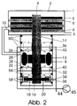
- stator washers 6 In the pump housing 1 with suction flange 2 and discharge opening 3 are the fixed pump-active components mounted as stator washers 6.
- the rotating Pump-active components are firmly connected to the rotor shaft 4 as rotor disks 5. This is set in rotation by a drive device 13.
- the rotor shaft is used in a system of gas bearings, which essentially consist of stator elements 18, 22 and 26 with gas supply devices 32, 34 and 36 and gas outlet openings 20, 24 and 28 exist.
- the stator elements 18, 22 and 26 are according to the invention via systems of elastic components 50, 54 and 58 with the bearing housing 8 connected. These elastic components also serve to seal between Broaching high and low pressures of the bearing housing 8 and the fore-vacuum space 7.
- the rigidity of the elastic Components 50, 54 and 58 is less than the rigidity of the system of gas bearings. she However, it must not fall below a certain limit, which is determined by the necessary narrow gap between the rotor and stator elements and those acting on the rotor Forces is specified.
- the gas flowing out of the gas outlet openings 20, 24 and 28 is via a system of gas discharge lines 38, 40 and 42 connected to a vacuum pump device 11, 22.
- This vacuum pump device can also serve as a backing pump for the Serve gas friction pump and in this case is connected to the fore-vacuum chamber 7.
- the gas friction pump can be operated with a higher pressure or even up to Atmospheric pressure emitting stage 9 may be provided.
- the gas discharge lines 38, 40 and 42 can then at a point 10 of this stage with a pressure level between Forevacuum pressure and atmospheric pressure are supplied.
- the gas supply lines 32, 34 and 36 are either at 44 with atmospheric pressure connected or connected to a compression device 45.
Landscapes
- Engineering & Computer Science (AREA)
- General Engineering & Computer Science (AREA)
- Mechanical Engineering (AREA)
- Physics & Mathematics (AREA)
- Fluid Mechanics (AREA)
- Non-Positive Displacement Air Blowers (AREA)
- Compressors, Vaccum Pumps And Other Relevant Systems (AREA)
- Magnetic Bearings And Hydrostatic Bearings (AREA)
- Structures Of Non-Positive Displacement Pumps (AREA)
Abstract
Description
Claims (9)
- Vakuumpumpe mit in einem Gehäuse (1), versehen mit Ansaugöffnung (2) und Auslaßöffnung (3), angeordneten feststehenden (6) und rotierenden (5) pumpaktiven Bauteilen, wobei die rotierenden pumpaktiven Bauteile auf einer Rotorwelle (4) montiert sind, welche in einem System von Gaslagern gehalten wird und die Gaslager im wesentlichen aus Statorelementen (18, 22, 26) mit Gaszufuhreinrichtungen (32, 34, 36) und Gasauslaßöffnungen (20, 24, 28) bestehen, dadurch gekennzeichnet, daß die Statorelemente (18, 22, 26) über Systeme elastischer Bauteile (50, 54, 58) mit dem Lagergehäuse (8) verbunden sind.
- Vakuumpumpe nach Anspruch 1, dadurch gekennzeichnet, daß die elastischen Bauteile (50, 54, 58) gleichzeitig zur Abdichtung zwischen Räumen hoher und niedriger Drücke des Lagergehäuses (8) bzw. der Vorvakuumkammer (7) dienen.
- Vakuumpumpe nach einem der vorangehenden Ansprüche, dadurch gekennzeichnet, daß die Steifigkeit der Systeme elastischer Bauteile (50, 54, 58) geringer ist als die Steifigkeit des Systems von Gaslagern.
- Vakuumpumpe nach einem der vorangehenden Ansprüche, dadurch gekennzeichnet, daß die Gasableitungen (38, 40, 42) an eine Vakuumpumpeinrichtung (11, 12) angeschlossen sind.
- Vakuumpumpe nach Anspruch 4, dadurch gekennzeichnet, daß die Vakuumpumpeinrichtung (11, 12) gleichzeitig als Vorvakuumpumpe für die Gasreibungspumpe vorgesehen ist.
- Vakuumpumpe nach einem der Ansprüche 1 ― 3, dadurch gekennzeichnet, daß sie mit einer nach Atmosphäre ausstoßenden Stufe (9) versehen ist und die Gasableitungen (38, 40, 42) an einer Stelle (10) dieser Stufe mit einem Druckniveau zwischen Vorvakuumdruck und Atmosphärendruck zugeführt werden.
- Vakuumpumpe nach Anspruch 6, dadurch gekennzeichnet, daß der Druck an der Stelle (10), zu welcher die Gasableitungen (38, 40, 42) geführt werden, dem Vorvakuumdruck entspricht.
- Vakuumpumpe nach einem der Ansprüche 1 ― 7, dadurch gekennzeichnet, daß die Gaszufuhrleitungen (32, 34, 36) über eine Leitung (44) mit dem äußeren Atmosphärendruck verbunden sind.
- Vakuumpumpe nach einem der Ansprüche 1 ― 7, dadurch gekennzeichnet, daß die Gaszufuhrleitungen (32, 34, 36) an einer Kompressionseinrichtung (45) angeschlossen sind.
Applications Claiming Priority (2)
| Application Number | Priority Date | Filing Date | Title |
|---|---|---|---|
| DE19915983 | 1999-04-09 | ||
| DE19915983A DE19915983A1 (de) | 1999-04-09 | 1999-04-09 | Vakuumpumpe mit Gaslagerung |
Publications (3)
| Publication Number | Publication Date |
|---|---|
| EP1043505A2 true EP1043505A2 (de) | 2000-10-11 |
| EP1043505A3 EP1043505A3 (de) | 2002-07-17 |
| EP1043505B1 EP1043505B1 (de) | 2006-01-18 |
Family
ID=7903978
Family Applications (1)
| Application Number | Title | Priority Date | Filing Date |
|---|---|---|---|
| EP00104954A Expired - Lifetime EP1043505B1 (de) | 1999-04-09 | 2000-03-08 | Vakuumpumpe mit Gaslagerung |
Country Status (5)
| Country | Link |
|---|---|
| US (1) | US6368082B1 (de) |
| EP (1) | EP1043505B1 (de) |
| JP (1) | JP2000297781A (de) |
| AT (1) | ATE316209T1 (de) |
| DE (2) | DE19915983A1 (de) |
Cited By (3)
| Publication number | Priority date | Publication date | Assignee | Title |
|---|---|---|---|---|
| EP1811176A4 (de) * | 2004-06-03 | 2008-11-19 | Edwards Japan Ltd | Vakuumabführvorrichtung |
| US20120020596A1 (en) * | 2009-01-26 | 2012-01-26 | Air Bearings Limited | Gas bearing and method of manufacturing the same |
| CN108730341A (zh) * | 2018-07-26 | 2018-11-02 | 中国工程物理研究院机械制造工艺研究所 | 一种基于气压控制的联锁结构及联锁方法 |
Families Citing this family (9)
| Publication number | Priority date | Publication date | Assignee | Title |
|---|---|---|---|---|
| GB0229356D0 (en) * | 2002-12-17 | 2003-01-22 | Boc Group Plc | Vacuum pumping arrangement |
| EP1559915B1 (de) * | 2004-01-29 | 2007-05-16 | Pfeiffer Vacuum GmbH | Gasreibungspumpe |
| JP4461180B2 (ja) * | 2004-09-22 | 2010-05-12 | ハミルトン・サンドストランド・コーポレイション | モーター冷却経路およびスラストベアリング負荷設計 |
| DE102005036942A1 (de) * | 2005-08-05 | 2007-02-15 | Leybold Vacuum Gmbh | Turbomaschine |
| DE102006020102A1 (de) | 2006-04-29 | 2007-10-31 | Leybold Vacuum Gmbh | Beschichtung für Gaslager |
| US7535150B1 (en) | 2006-05-08 | 2009-05-19 | Prc Laser Corporation | Centrifugal turbine blower with gas foil bearings |
| DE102008034948A1 (de) * | 2008-07-26 | 2010-01-28 | Pfeiffer Vacuum Gmbh | Vakuumpumpe |
| GB2588146A (en) * | 2019-10-09 | 2021-04-21 | Edwards Ltd | Vacuum pump |
| CN112128139A (zh) * | 2020-08-13 | 2020-12-25 | 北京点域科技有限公司 | 一种能改变出水管方向的水泵 |
Citations (4)
| Publication number | Priority date | Publication date | Assignee | Title |
|---|---|---|---|---|
| DE2255618A1 (de) | 1971-11-16 | 1973-05-24 | Cit Alcatel | Stehender zapfen bzw. pivotzapfen fuer drehende molekularpumpen |
| DE2359456A1 (de) | 1973-11-29 | 1975-06-05 | Leybold Heraeus Gmbh & Co Kg | Turbomolekularvakuumpumpe mit gasgelagertem rotor |
| DE3891280T1 (de) | 1988-03-30 | 1990-04-05 | Vladimir Pavlovic Sergeev | Turbomolekular-vakuumpumpe |
| DE4436156C1 (de) | 1994-10-10 | 1996-03-21 | Heinzl Joachim | Aerostatisches Lager und Verfahren zur Herstellung eines aerostatischen Lagers |
Family Cites Families (10)
| Publication number | Priority date | Publication date | Assignee | Title |
|---|---|---|---|---|
| US3058785A (en) * | 1959-09-21 | 1962-10-16 | Lucas Industries Ltd | Gas lubricated bearings |
| GB1018300A (en) * | 1963-03-12 | 1966-01-26 | Micro Turbines Ltd | Improvements in or relating to high speed gas driven turbines |
| IT1032818B (it) | 1975-05-06 | 1979-06-20 | Rava E | Perfezionamento alle pompe turbomo lecolari |
| DE3537822A1 (de) * | 1985-10-24 | 1987-04-30 | Leybold Heraeus Gmbh & Co Kg | Vakuumpumpe mit gehaeuse und rotor |
| JP2602648B2 (ja) * | 1987-01-14 | 1997-04-23 | キヤノン株式会社 | 回転駆動装置 |
| EP0344345B1 (de) * | 1988-06-01 | 1991-09-18 | Leybold Aktiengesellschaft | Pumpsystem für ein Lecksuchgerät |
| FR2683277B1 (fr) * | 1991-11-04 | 1995-01-13 | Cit Alcatel | Entretoise a epaisseur ajustable. |
| US5501583A (en) * | 1992-08-19 | 1996-03-26 | Hitachi, Ltd. | Turbo vacuum pump |
| DE4314419A1 (de) * | 1993-05-03 | 1994-11-10 | Leybold Ag | Reibungsvakuumpumpe mit Lagerabstützung |
| JP3088593B2 (ja) * | 1993-07-16 | 2000-09-18 | 光洋精工株式会社 | 静圧気体軸受 |
-
1999
- 1999-04-09 DE DE19915983A patent/DE19915983A1/de not_active Withdrawn
-
2000
- 2000-03-08 EP EP00104954A patent/EP1043505B1/de not_active Expired - Lifetime
- 2000-03-08 AT AT00104954T patent/ATE316209T1/de not_active IP Right Cessation
- 2000-03-08 DE DE50012061T patent/DE50012061D1/de not_active Expired - Lifetime
- 2000-03-16 JP JP2000073671A patent/JP2000297781A/ja active Pending
- 2000-04-05 US US09/543,300 patent/US6368082B1/en not_active Expired - Fee Related
Patent Citations (4)
| Publication number | Priority date | Publication date | Assignee | Title |
|---|---|---|---|---|
| DE2255618A1 (de) | 1971-11-16 | 1973-05-24 | Cit Alcatel | Stehender zapfen bzw. pivotzapfen fuer drehende molekularpumpen |
| DE2359456A1 (de) | 1973-11-29 | 1975-06-05 | Leybold Heraeus Gmbh & Co Kg | Turbomolekularvakuumpumpe mit gasgelagertem rotor |
| DE3891280T1 (de) | 1988-03-30 | 1990-04-05 | Vladimir Pavlovic Sergeev | Turbomolekular-vakuumpumpe |
| DE4436156C1 (de) | 1994-10-10 | 1996-03-21 | Heinzl Joachim | Aerostatisches Lager und Verfahren zur Herstellung eines aerostatischen Lagers |
Cited By (4)
| Publication number | Priority date | Publication date | Assignee | Title |
|---|---|---|---|---|
| EP1811176A4 (de) * | 2004-06-03 | 2008-11-19 | Edwards Japan Ltd | Vakuumabführvorrichtung |
| US20120020596A1 (en) * | 2009-01-26 | 2012-01-26 | Air Bearings Limited | Gas bearing and method of manufacturing the same |
| US8882353B2 (en) * | 2009-01-26 | 2014-11-11 | Ralf Dupont | Gas bearing and method of manufacturing the same |
| CN108730341A (zh) * | 2018-07-26 | 2018-11-02 | 中国工程物理研究院机械制造工艺研究所 | 一种基于气压控制的联锁结构及联锁方法 |
Also Published As
| Publication number | Publication date |
|---|---|
| DE50012061D1 (de) | 2006-04-06 |
| US6368082B1 (en) | 2002-04-09 |
| DE19915983A1 (de) | 2000-10-12 |
| EP1043505A3 (de) | 2002-07-17 |
| JP2000297781A (ja) | 2000-10-24 |
| ATE316209T1 (de) | 2006-02-15 |
| EP1043505B1 (de) | 2006-01-18 |
Similar Documents
| Publication | Publication Date | Title |
|---|---|---|
| EP1565663B1 (de) | Turbomolekularvakuumpumpe | |
| EP2826999B1 (de) | Vakuumpumpe | |
| EP2060794B1 (de) | Vakuumpumpe mit Schmiermittelpumpe | |
| EP1043505A2 (de) | Vakuumpumpe mit Gaslagerung | |
| EP1953390A1 (de) | Vorrichtung und Verfahren zum Axialschubausgleich | |
| DE3345684A1 (de) | Abgedichteter kompressor in spiralbauweise | |
| EP3071840B1 (de) | Entlastungseinrichtung | |
| EP1936200A2 (de) | Schmiermittelgedichtete Drehschiebervakuumpumpe | |
| DE3150033A1 (de) | Vakuumpumpe mit einem saugstutzen-ventil und betriebsverfahren dafuer | |
| DE102022103193A1 (de) | Spiralverdichter mit einer Zentrifugalölpumpe | |
| EP3734078B1 (de) | Turbomolekularpumpe und verfahren zur herstellung einer statorscheibe für eine solche | |
| EP4194700B1 (de) | Vakuumpumpe mit einer holweck-pumpstufe mit veränderlicher holweck-geometrie | |
| DE19631824A1 (de) | Kreiselpumpenlagerung mit Axialschubausgleich | |
| EP0198936B1 (de) | Mehrstufige Vakuumpumpe | |
| EP0642628A1 (de) | Doppelpumpe. | |
| DE10154552A1 (de) | Kraftstoff-Pumpeinrichtung für ein Kraftstoffsystem einer Brennkraftmaschine sowie Kraftstoffsystem | |
| DE19809957A1 (de) | Mehrwellenvakuumpumpe | |
| EP2927500B1 (de) | Verfahren und system zur versorgung einer lageranordnung | |
| DE3032967A1 (de) | Molekularpumpe, insbesondere turbomolekularpumpe, und damit ausgeruestetes pumpsystem | |
| EP2148094A2 (de) | Vakuumpumpe | |
| DE19633559A1 (de) | Durchflußregler | |
| DE102020116770B4 (de) | Vakuumpumpe mit integriertem miniaturventil | |
| DE4425406A1 (de) | Abstützkonstruktion für eine Drehwelle eines Kompressors | |
| EP3267040B1 (de) | Turbomolekularpumpe | |
| EP3650702B1 (de) | Verwendung eines synthetischen öls in einer vakuumpumpe und vakuumpumpe |
Legal Events
| Date | Code | Title | Description |
|---|---|---|---|
| PUAI | Public reference made under article 153(3) epc to a published international application that has entered the european phase |
Free format text: ORIGINAL CODE: 0009012 |
|
| AK | Designated contracting states |
Kind code of ref document: A2 Designated state(s): AT BE CH CY DE DK ES FI FR GB GR IE IT LI LU MC NL PT SE |
|
| AX | Request for extension of the european patent |
Free format text: AL;LT;LV;MK;RO;SI |
|
| PUAL | Search report despatched |
Free format text: ORIGINAL CODE: 0009013 |
|
| AK | Designated contracting states |
Kind code of ref document: A3 Designated state(s): AT BE CH CY DE DK ES FI FR GB GR IE IT LI LU MC NL PT SE |
|
| AX | Request for extension of the european patent |
Free format text: AL;LT;LV;MK;RO;SI |
|
| 17P | Request for examination filed |
Effective date: 20021213 |
|
| AKX | Designation fees paid |
Designated state(s): AT BE CH CY DE DK ES FI FR GB GR IE IT LI LU MC NL PT SE |
|
| 17Q | First examination report despatched |
Effective date: 20050210 |
|
| GRAP | Despatch of communication of intention to grant a patent |
Free format text: ORIGINAL CODE: EPIDOSNIGR1 |
|
| GRAS | Grant fee paid |
Free format text: ORIGINAL CODE: EPIDOSNIGR3 |
|
| GRAA | (expected) grant |
Free format text: ORIGINAL CODE: 0009210 |
|
| AK | Designated contracting states |
Kind code of ref document: B1 Designated state(s): AT BE CH CY DE DK ES FI FR GB GR IE IT LI LU MC NL PT SE |
|
| PG25 | Lapsed in a contracting state [announced via postgrant information from national office to epo] |
Ref country code: FI Free format text: LAPSE BECAUSE OF FAILURE TO SUBMIT A TRANSLATION OF THE DESCRIPTION OR TO PAY THE FEE WITHIN THE PRESCRIBED TIME-LIMIT Effective date: 20060118 Ref country code: IE Free format text: LAPSE BECAUSE OF FAILURE TO SUBMIT A TRANSLATION OF THE DESCRIPTION OR TO PAY THE FEE WITHIN THE PRESCRIBED TIME-LIMIT Effective date: 20060118 |
|
| REG | Reference to a national code |
Ref country code: GB Ref legal event code: FG4D Free format text: NOT ENGLISH |
|
| REG | Reference to a national code |
Ref country code: CH Ref legal event code: EP |
|
| REG | Reference to a national code |
Ref country code: IE Ref legal event code: FG4D Free format text: LANGUAGE OF EP DOCUMENT: GERMAN |
|
| PGFP | Annual fee paid to national office [announced via postgrant information from national office to epo] |
Ref country code: CH Payment date: 20060307 Year of fee payment: 7 |
|
| PG25 | Lapsed in a contracting state [announced via postgrant information from national office to epo] |
Ref country code: AT Free format text: LAPSE BECAUSE OF NON-PAYMENT OF DUE FEES Effective date: 20060308 |
|
| PG25 | Lapsed in a contracting state [announced via postgrant information from national office to epo] |
Ref country code: MC Free format text: LAPSE BECAUSE OF NON-PAYMENT OF DUE FEES Effective date: 20060331 Ref country code: BE Free format text: LAPSE BECAUSE OF NON-PAYMENT OF DUE FEES Effective date: 20060331 Ref country code: LU Free format text: LAPSE BECAUSE OF NON-PAYMENT OF DUE FEES Effective date: 20060331 |
|
| REF | Corresponds to: |
Ref document number: 50012061 Country of ref document: DE Date of ref document: 20060406 Kind code of ref document: P |
|
| GBT | Gb: translation of ep patent filed (gb section 77(6)(a)/1977) |
Effective date: 20060316 |
|
| PG25 | Lapsed in a contracting state [announced via postgrant information from national office to epo] |
Ref country code: SE Free format text: LAPSE BECAUSE OF FAILURE TO SUBMIT A TRANSLATION OF THE DESCRIPTION OR TO PAY THE FEE WITHIN THE PRESCRIBED TIME-LIMIT Effective date: 20060418 Ref country code: DK Free format text: LAPSE BECAUSE OF FAILURE TO SUBMIT A TRANSLATION OF THE DESCRIPTION OR TO PAY THE FEE WITHIN THE PRESCRIBED TIME-LIMIT Effective date: 20060418 |
|
| PG25 | Lapsed in a contracting state [announced via postgrant information from national office to epo] |
Ref country code: ES Free format text: LAPSE BECAUSE OF FAILURE TO SUBMIT A TRANSLATION OF THE DESCRIPTION OR TO PAY THE FEE WITHIN THE PRESCRIBED TIME-LIMIT Effective date: 20060429 |
|
| PG25 | Lapsed in a contracting state [announced via postgrant information from national office to epo] |
Ref country code: PT Free format text: LAPSE BECAUSE OF FAILURE TO SUBMIT A TRANSLATION OF THE DESCRIPTION OR TO PAY THE FEE WITHIN THE PRESCRIBED TIME-LIMIT Effective date: 20060619 |
|
| REG | Reference to a national code |
Ref country code: IE Ref legal event code: FD4D |
|
| ET | Fr: translation filed | ||
| PLBE | No opposition filed within time limit |
Free format text: ORIGINAL CODE: 0009261 |
|
| STAA | Information on the status of an ep patent application or granted ep patent |
Free format text: STATUS: NO OPPOSITION FILED WITHIN TIME LIMIT |
|
| 26N | No opposition filed |
Effective date: 20061019 |
|
| REG | Reference to a national code |
Ref country code: CH Ref legal event code: PL |
|
| BERE | Be: lapsed |
Owner name: PFEIFFER VACUUM G.M.B.H. Effective date: 20060331 |
|
| PG25 | Lapsed in a contracting state [announced via postgrant information from national office to epo] |
Ref country code: LI Free format text: LAPSE BECAUSE OF NON-PAYMENT OF DUE FEES Effective date: 20070331 Ref country code: CH Free format text: LAPSE BECAUSE OF NON-PAYMENT OF DUE FEES Effective date: 20070331 |
|
| PG25 | Lapsed in a contracting state [announced via postgrant information from national office to epo] |
Ref country code: GR Free format text: LAPSE BECAUSE OF FAILURE TO SUBMIT A TRANSLATION OF THE DESCRIPTION OR TO PAY THE FEE WITHIN THE PRESCRIBED TIME-LIMIT Effective date: 20060419 |
|
| PGFP | Annual fee paid to national office [announced via postgrant information from national office to epo] |
Ref country code: NL Payment date: 20080131 Year of fee payment: 9 |
|
| PG25 | Lapsed in a contracting state [announced via postgrant information from national office to epo] |
Ref country code: CY Free format text: LAPSE BECAUSE OF FAILURE TO SUBMIT A TRANSLATION OF THE DESCRIPTION OR TO PAY THE FEE WITHIN THE PRESCRIBED TIME-LIMIT Effective date: 20060118 |
|
| NLV4 | Nl: lapsed or anulled due to non-payment of the annual fee |
Effective date: 20091001 |
|
| PG25 | Lapsed in a contracting state [announced via postgrant information from national office to epo] |
Ref country code: NL Free format text: LAPSE BECAUSE OF NON-PAYMENT OF DUE FEES Effective date: 20091001 |
|
| PGFP | Annual fee paid to national office [announced via postgrant information from national office to epo] |
Ref country code: FR Payment date: 20120307 Year of fee payment: 13 |
|
| REG | Reference to a national code |
Ref country code: FR Ref legal event code: ST Effective date: 20131129 |
|
| PG25 | Lapsed in a contracting state [announced via postgrant information from national office to epo] |
Ref country code: FR Free format text: LAPSE BECAUSE OF NON-PAYMENT OF DUE FEES Effective date: 20130402 |
|
| PGFP | Annual fee paid to national office [announced via postgrant information from national office to epo] |
Ref country code: DE Payment date: 20140318 Year of fee payment: 15 |
|
| PGFP | Annual fee paid to national office [announced via postgrant information from national office to epo] |
Ref country code: IT Payment date: 20140327 Year of fee payment: 15 |
|
| PGFP | Annual fee paid to national office [announced via postgrant information from national office to epo] |
Ref country code: GB Payment date: 20140314 Year of fee payment: 15 |
|
| REG | Reference to a national code |
Ref country code: DE Ref legal event code: R119 Ref document number: 50012061 Country of ref document: DE |
|
| GBPC | Gb: european patent ceased through non-payment of renewal fee |
Effective date: 20150308 |
|
| PG25 | Lapsed in a contracting state [announced via postgrant information from national office to epo] |
Ref country code: IT Free format text: LAPSE BECAUSE OF NON-PAYMENT OF DUE FEES Effective date: 20150308 |
|
| PG25 | Lapsed in a contracting state [announced via postgrant information from national office to epo] |
Ref country code: GB Free format text: LAPSE BECAUSE OF NON-PAYMENT OF DUE FEES Effective date: 20150308 Ref country code: DE Free format text: LAPSE BECAUSE OF NON-PAYMENT OF DUE FEES Effective date: 20151001 |