EP1043703A1 - Geldverarbeitungsvorrichtung - Google Patents
Geldverarbeitungsvorrichtung Download PDFInfo
- Publication number
- EP1043703A1 EP1043703A1 EP00302917A EP00302917A EP1043703A1 EP 1043703 A1 EP1043703 A1 EP 1043703A1 EP 00302917 A EP00302917 A EP 00302917A EP 00302917 A EP00302917 A EP 00302917A EP 1043703 A1 EP1043703 A1 EP 1043703A1
- Authority
- EP
- European Patent Office
- Prior art keywords
- power
- money
- mode
- coin
- dispense
- Prior art date
- Legal status (The legal status is an assumption and is not a legal conclusion. Google has not performed a legal analysis and makes no representation as to the accuracy of the status listed.)
- Withdrawn
Links
Images


Classifications
-
- G—PHYSICS
- G07—CHECKING-DEVICES
- G07F—COIN-FREED OR LIKE APPARATUS
- G07F19/00—Complete banking systems; Coded card-freed arrangements adapted for dispensing or receiving monies or the like and posting such transactions to existing accounts, e.g. automatic teller machines
- G07F19/20—Automatic teller machines [ATMs]
- G07F19/201—Accessories of ATMs
-
- G—PHYSICS
- G07—CHECKING-DEVICES
- G07F—COIN-FREED OR LIKE APPARATUS
- G07F5/00—Coin-actuated mechanisms; Interlocks
- G07F5/24—Coin-actuated mechanisms; Interlocks with change-giving
Definitions
- This invention relates to apparatus for handling units of currency.
- the invention will be described mainly in the context of coin handling, but is also applicable to apparatus which also or alternatively handles other units of currency, such as banknotes or the like.
- Such coin handling apparatus is typically provided in vending machines or payphones, which are required to operate unattended for long periods of time. Typically, power is supplied to the coin handling apparatus from the machine within which it is located, although some currency handling apparatus has mains supply ports.
- the voltage supplied to the apparatus may differ from the voltage level it requires for normal operation.
- European mains power nominal supply levels vary at present between 240-220 volts, and may in future be set with a relatively wide tolerance.
- the voltage may vary according to the location of the apparatus. Equally, the voltage may vary over time, since in some areas voltages are reduced at peak usage periods.
- FR 2355418 discloses a coin operated telephone with a non-volatile credit memory, with a capacitor which may also supply energy to a rocker within a coin refund mechanism, in the event of power failure.
- a vending machine which reduces average power used by, for example, its heating and cooling devices during periods of the day when an office is closed (which do not apparently coincide with reduced supply power conditions) is disclosed in US 5868274.
- the present invention provides a currency handling apparatus which can sense the probable occurrence of a reduced power condition, and which can, in response, continue to operate in a selected reduced power mode, in which its currency handling functions are still performed.
- the reduced power mode may provide one or more modes of operating a currency dispensing subsystem at reduced power.
- a plurality of actuators e.g. motors
- the reduced power mode may sequentially be activated instead.
- power to peripheral devices not directly concerned with the transport or handling of currency such as displays
- the reduced power mode may involve the provision of a predetermined delay between successive operations of power-consuming components, the delay being sufficient to permit at least some substantial re-charging of the reservoir.
- a delay may be provided between successive operations of electro mechanical currency handling actuators (such as solenoids driving the accept gate and separator gates of a currency acceptor, and/or the dispense motors or dispense solenoids of a change dispenser).
- electro mechanical currency handling actuators such as solenoids driving the accept gate and separator gates of a currency acceptor, and/or the dispense motors or dispense solenoids of a change dispenser.
- a delay may be provided between successive actuations of the same device, or between successive actions of any such device.
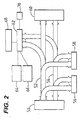
- the coin handling apparatus 2 in the vending machine includes a coin validator 4 for receiving coins as indicated at 6.
- the validator provides signals indicating whether the coins are acceptable, and if so the denomination of the coins.
- validators are known, including validators using optical, acoustic and inductive techniques. Examples of such validators are described in, amongst others, GB 1397083, GB 1443934, GB 2254948, GB 2094008 and GB 2288266, the contents of which documents are incorporated herein by reference.
- Acceptable coins then enter a coin separator 10, which has a number of gates 5, 7, 9, 11 (not shown) actuated by respective solenoids 205, 207, 209, 211 controlled by the circuitry of the apparatus for selectively diverting the coins from a main path 12 into any of a number of further paths 14, 15, 16 and 17, or allowing the coins to proceed along the path 12 to a path 20 leading to a cashbox 21. If the coins are unacceptable, instead of entering the separator 10 they are diverted straight to a reject slot via a path 30, by an accept gate 3 driven by an actuating solenoid 203.
- Each of the paths 14, 15, 16 and 17 leads to a respective one of four coin tubes or containers 22, 24 and 26 and 28.
- Each of these containers is arranged to store a vertical stack of coins of a particular denomination. Although only four containers are shown, any number may be provided.
- a dispenser indicated schematically at 29 is operable to dispense coins from the containers when change is to be given by the apparatus.
- the dispensed coins are delivered to a refund path 31.
- the dispenser comprises a pair of motors 292, 294 each able to dispense a coin from one of two tubes (22, 24; or 26, 28) beneath which it is located, on energising of selected windings by the circuitry of the apparatus.
- the tubes 22, 24, 26, 28 are provided in a removable cassette, and the tubes themselves are removable from the cassette, as described in GB 2 246 897 A, the contents of which are incorporated herein by reference.
- the circuit of the present embodiment of the invention incorporates a microprocessor 50 connected to data and address buses 52 and 54. Although separate buses are shown, data and address signals could instead be multiplexed on a single bus. A bus for control signals could also be provided. An LSI could replace the microprocessor.
- the microprocessor 50 is connected via the buses 52 and 54 to a read-only memory (ROM) 56 and a random access memory (RAM) 58.
- the ROM 56 stores the program controlling the overall operation of the microprocessor 50
- the RAM 58 is used by the microprocessor 50 as a scratch-pad memory.
- the microprocessor 50, the ROM 56 and the RAM 58 are, in the described implementation, combined on a single integrated circuit.
- the microprocessor 50 may also be connected via the buses 52 and 54 to an Electrically Alterable ROM (EAROM) such as a Flash memory, 60, for storing a variety of alterable parameters.
- EAROM Electrically Alterable ROM
- Flash memory 60
- the microprocessor 50 is also coupled via the buses 52 and 54 to input/output circuitry indicated at 62.
- the circuitry 62 includes user-operable switches, at least one level sensor for each of the coin containers 22, 24, 26, 28, circuits for operating the dispenser 29 and the gates of the coin separator 10, the circuitry of the coin validator 4, and a credit display 63 visible to a user of the apparatus for displaying an accumulated credit value and an indication when insufficient coins are stored to guarantee that change will be available.
- the circuitry 62 is connected to a display 68 visible to the operator, and to a keypad 70 accessible only to the operator.
- the input/output circuitry 62 also includes an interface 72 between the control circuit of the apparatus and a vending machine circuit board 64 to which it is connected, and a further interface to an audit device 66.
- the microprocessor 50 In operation of the apparatus the microprocessor 50 successively tests the signals from the validator to determine whether a coin has been inserted in the apparatus. When a credit has been accumulated, the microprocessor also tests signals from the vending machine to determine whether a vending operation has been carried out. In response to various signals received by the microprocessor 50, various parts of the program stored in the ROM 56 are carried out.
- the microprocessor is thus arranged to operate and receive signals from the level sensors of the coin containers 22, 24, 26, 28, and to control the accept gate and the gates in the separator 10 in order to deliver the coins to the required locations, and is also operable to cause appropriate information to be shown on the displays of the apparatus and to deliver signals to the vending machine to permit or prevent vending operations typically through vendor price relays.
- the microprocessor is also operable to control the dispenser to deliver appropriate amounts of change.
- the interface 72 to the vending machine includes a power supply line (and, where necessary, an earth line) carrying, for example, low voltage DC.
- the interface may be configured to accept a Multi-Drop Bus (MDB) connector, an electromechanical vending machine connector, or both, as well as other possible interfaces which supply power.
- MDB Multi-Drop Bus
- the power line from the interface is routed to a power supply unit 74, performs any necessary smoothing and voltage step-down. Between the power line from the interface 72 and ground is a capacitor 76. Under ordinary conditions, the capacitor is therefore held at the line voltage of the power line from the interface. The output of the power supply unit 74 appears on a power bus line supplied to components of the apparatus.
- the charge stored on the capacitor 76 provides additional supply current, for a predetermined period of time related to the capacitance of the capacitor. It is then subsequently recharged from the power supply line from the interface 72.
- the time taken to recharge may be, for example, 100-200ms.
- the accept gate 3 is energised to route it to the separator 10, by the acceptor gate solenoid 203, and the selected separator gate is actuated by its solenoid to allow the coin to pass to the desired coin tube.
- the gate and the selector solenoids are energised for a period of time sufficient to guarantee that the coin passes completely through; they are typically energised together.
- the microprocessor 50 also controls the supply of power to electromechanical components such as the dispenser motors 292 and 294, and separator solenoids (for example 205 as shown). Finally, the microprocessor 50 controls the supply of power to a plurality of relays (such as the relay for the exact change light, and vend relays), display devices, and other input/output devices, via respective switches 82-88. Thus, the microprocessor 50 is able to prevent the supply of power from the power bus to the windings of relays or other output devices where this is not necessary.
- step 102 the coins to be dispensed are selected (for example as disclosed in GB 2284090) and in step 104, a dispense cycle operates to dispense the selected coin or coins.
- step 106 two tubes containing coins selected from those to be dispensed are selected, and in step 108 the two motors 292, 294 are operated simultaneously to dispense a coin from each tube.
- step 110 it is determined whether further coins remain to be dispensed and, if so, step 106 is repeated.
- the credit accumulated is displayed on the display 63.
- the type of device for example vending machine
- it may be required to perform other operations such as switching relays for use by the vending machine.
- the voltage is tapped at a point after the capacitor 76 and fed to an analog to digital converter 51 the digital output of which is supplied to the microprocessor 50.
- the analog to digital converter may additionally be sampling other signals, multiplexed together at its input.
- the microprocessor Periodically (for example, several times a second) the microprocessor reads the analog to digital converter output, which therefore corresponds to the voltage over the capacitor 76, in a step 120 of Figure 6.
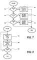
- the microprocessor 50 determines whether there has been a change from the previous reading and, if not, no further action is taken in that cycle. If the power supply reading has changed, the microprocessor 50 proceeds to select one of a plurality of different operating modes in dependence upon the sensed power level, as follows.
- a step 124 the microprocessor 50 determines whether the voltage across the capacitor exceeds 50% of a reference value (corresponding to the nominal voltage on the interface) and, if so, normal operation mode is selected in step 126. In this mode, operation proceeds as described above and as known in the prior art.
- step 128 the microprocessor 50 determines whether it exceeds 30% of the reference value and, if so, in a step 130 selects a second dispense mode (a reduced power mode), in which the process of Figure 8 replaces that of Figure 5.
- the processor selects one tube at a time in step 156, and in step 158 energises the winding of one of the motors 292, 294 to dispense from the selected tube.
- step 160 the microprocessor determines whether all coins have been dispensed and, if not, returns to step 156.
- step 132 the microprocessor 50 tests whether it is greater than 10% of the reference value and, if so, in step 134, the microprocessor selects a third (reduced power) dispense mode for future dispenses.
- the third dispense mode is illustrated in Figure 9, in which steps 156, 158 and 160 have the same meaning as described in relation to Figure 8 above.
- the microprocessor 50 waits for a predetermined period T (related to the time constant, and hence capacitance, of the capacitor 76) before proceeding to step 160.
- T related to the time constant, and hence capacitance, of the capacitor 76
- the apparatus pauses between dispenses for long enough for the capacitor 76 to re-charge fully or at least substantially, ensuring that energy from the capacitor is available for the next dispense operation.
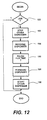
- step 138 the microprocessor selects a fourth dispense mode.
- the fourth dispense mode is shown in Figure 10.
- step 162 the microprocessor switches off the credit display 63, and any other peripheral devices within the input output circuitry 62 (for example, where an "exact change” relay is provided for the vending machine to show an “exact change only” light, this too is powered down).
- step 164 the process of Figure 9 is performed to dispense the required coins in change.
- step 166 power is restored to the peripheral devices.
- each of the peripheral devices concerned is provided on a separate printed circuit board, to which the power bus is routed, via a switch 82-88 controlled from the processor 50, so that power to each board can be switched out by the processor 50.
- the present embodiment is able to make use of different modes of accepting coins. Accordingly, referring to Figure 7, following the selection of a dispense mode according to the process of Figure 6, in a step 142, the processor 50 determines whether the voltage over the capacitor 76 is greater than 45% of the stored reference value and, if so, switches off the power to the credit display 63.
- the microprocessor 50 selects a second acceptance mode in which, after selecting the solenoids to be actuated (e.g. the accept gate solenoid and one or more solenoids in the selector 10) in step 168, these solenoids are actuated in step 170. If a further coin is detected in step 172 by the sensing system, then in a step 174, the microprocessor waits a predetermined period of time T sufficient to allow the capacitor 76 to re-charge at least partially, before selecting the solenoids to be opened in step 168.
- the solenoids to be actuated e.g. the accept gate solenoid and one or more solenoids in the selector 10
- this corresponds to a slowing of the acceptance rate from some maximum rate corresponding to a minimum time between successive openings of the accept gate which is used in the normal acceptance mode, towards a slower acceptance rate used in the lower power mode.
- a third accept mode is selected in which the microprocessor 50 leaves a predetermined delay between the actuations of any power consuming device so that, for example, as disclosed with reference to Figure 11, a predetermined time is allowed to elapse between subsequent acceptances of coins; then a predetermined time is allowed to elapse before firing relays such as a vend relay through switches 82-88; then a predetermined time is allowed to elapse before dispensing change commences, and then a predetermined time elapses between each successive dispensing operation.
- the present invention provides a plurality of further power reduction options, useable separately or together, and with or without the above described embodiment.
- the apparatus described above is designed for use in vending machines operating to more than one different interface standard and, specifically, where it can be used either with an electromechanical vending machine or a vending machine having the Multi-Drop Bus (MDB) MDB/ICP interface specified by the North American Vending Machines Association (NAMA) and the European Vending Machine Association (EVA), it may provide outputs (in the form of a credit display 63, and exact change relay, and other relays) which are not required for one of the interfaces (the MDB interface).
- MDB Multi-Drop Bus
- NAMA North American Vending Machines Association
- EDA European Vending Machine Association
- the microprocessor 50 may switch off power to any peripheral devices not necessary for that interface.
- the overall power used by the apparatus may be reduced, without requiring tests of the power level supplied.
- a jam is detected (for example as discussed above) in one of the dispense motors 292, 294 (for example the dispenser 292) and, in a step 182, the other dispenser (for example 294) is stopped within its dispensing operation.
- a step 184 the first dispenser 292 is reversed briefly, as disclosed in our above reference earlier application and, in a step 186, the microprocessor 50 waits a predetermined time T to allow the capacitor 76 to re-charge.
- step 188 the original forward dispensing motion of the first dispenser 292 is resumed, and on completion of its dispensing cycle, in a step 190 the second dispenser 294 is re-started to complete its own dispensing operation.
- the hammer action is enhanced in low power conditions by permitting the power supply capacitor 76 to recharge in the absence of other significant power drains, before resuming dispensing.
- the microprocessor 50 may be arranged to enter a low power mode within those particular times, and may comprise for that purpose a real time clock.
- an input for example using the operator actuated keypad
- the microprocessor 50 may select a reduce power mode
- the apparatus should be capable of operating in normal, rather than reduced power, mode during at least most of the day, entering reduced power mode only on exceptional supply voltage conditions.
- the thresholds indicated are purely by way of example and any suitable thresholds can be adopted, which are either absolute values or a pecentages of a reference supply value. Whereas a predetermined time to recharge the capacitor has been indicated, it would be possible to provide for the calculation of a time to recharge the capacitor based on the measured supply voltage.
Landscapes
- Physics & Mathematics (AREA)
- General Physics & Mathematics (AREA)
- Business, Economics & Management (AREA)
- Accounting & Taxation (AREA)
- Finance (AREA)
- Control Of Vending Devices And Auxiliary Devices For Vending Devices (AREA)
Applications Claiming Priority (2)
| Application Number | Priority Date | Filing Date | Title |
|---|---|---|---|
| GB9907952 | 1999-04-07 | ||
| GB9907952A GB2348730B (en) | 1999-04-07 | 1999-04-07 | Currency handling apparatus |
Publications (1)
| Publication Number | Publication Date |
|---|---|
| EP1043703A1 true EP1043703A1 (de) | 2000-10-11 |
Family
ID=10851100
Family Applications (1)
| Application Number | Title | Priority Date | Filing Date |
|---|---|---|---|
| EP00302917A Withdrawn EP1043703A1 (de) | 1999-04-07 | 2000-04-06 | Geldverarbeitungsvorrichtung |
Country Status (3)
| Country | Link |
|---|---|
| US (1) | US6615970B1 (de) |
| EP (1) | EP1043703A1 (de) |
| GB (1) | GB2348730B (de) |
Families Citing this family (5)
| Publication number | Priority date | Publication date | Assignee | Title |
|---|---|---|---|---|
| US6742644B1 (en) * | 2000-11-27 | 2004-06-01 | Jcm American Corporation | Note acceptor-dispenser validator |
| EP1387326B1 (de) * | 2002-08-01 | 2008-06-25 | Harting Vending GmbH & Co. KG | Verfahren zur Betrugsverhinderung für münz-oder banknotenbetätigte Automaten |
| CA2523925A1 (en) * | 2005-10-20 | 2007-04-20 | Cashcode Company Inc. | Banknote recycler protocol adapter |
| US8827777B2 (en) * | 2007-05-24 | 2014-09-09 | National Rejectors, Inc. Gmbh | Method for operating a coin dispensing device and a coin dispensing device |
| JP6203617B2 (ja) * | 2013-12-05 | 2017-09-27 | 株式会社日本コンラックス | 硬貨処理装置 |
Citations (10)
| Publication number | Priority date | Publication date | Assignee | Title |
|---|---|---|---|---|
| GB1397083A (en) | 1971-05-24 | 1975-06-11 | Mars Inc | Coin selector utilizing inductive sensors |
| FR2355418A1 (fr) | 1976-06-15 | 1978-01-13 | Sodeco Compteurs De Geneve | Telephone a pieces de monnaie |
| GB2094008A (en) | 1981-02-11 | 1982-09-08 | Mars Inc | Improvements in and relating to apparatus for checking the validity of coins |
| GB2137793A (en) | 1983-02-08 | 1984-10-10 | Mars Inc | Coin handling apparatus |
| EP0184393A2 (de) | 1984-12-05 | 1986-06-11 | Mars Incorporated | Münzprüfvorrichtung |
| US4848556A (en) * | 1985-04-08 | 1989-07-18 | Qonaar Corporation | Low power coin discrimination apparatus |
| US4979208A (en) | 1988-06-29 | 1990-12-18 | Mars Incorporated | Method and apparatus for electronic payphone open switch interval management |
| GB2246898A (en) | 1990-08-10 | 1992-02-12 | Mars Inc | Coin testing |
| US5109972A (en) * | 1989-07-24 | 1992-05-05 | Duncan Industries Parking Control Systems Corp. | Coin operated timing mechanism |
| US5868274A (en) | 1996-07-13 | 1999-02-09 | Kwangju Electronics Co., Ltd. | Power saving apparatus of an automatic vending machine and method thereof |
Family Cites Families (6)
| Publication number | Priority date | Publication date | Assignee | Title |
|---|---|---|---|---|
| US4383210A (en) * | 1980-06-18 | 1983-05-10 | Wilkinson Rudolph P | Apparatus and method for recharging an energy storage device |
| US4604557A (en) * | 1984-10-10 | 1986-08-05 | Mars Incorporated | Vending machine power switching apparatus |
| DE4025448A1 (de) | 1990-08-10 | 1992-02-13 | Steyr Daimler Puch Ag | Kraftfahrzeuggetriebe mit koerperschallarmer schaltvorrichtung |
| EP0556278B2 (de) * | 1990-11-07 | 2002-05-22 | Mars Incorporated | Verfahren und vorrichtung für eine batteriebetriebene verkaufs- und ausgabevorrichtung mit niedrigem energieverbrauch |
| US5564547A (en) * | 1993-06-03 | 1996-10-15 | Maxtrol Corporation | Method and apparatus for converting single price vending machines to multiple price vending machines |
| US6053299A (en) * | 1999-04-15 | 2000-04-25 | Money Controls, Inc. | Apparatus and method for processing coins in a host machine |
-
1999
- 1999-04-07 GB GB9907952A patent/GB2348730B/en not_active Expired - Fee Related
-
2000
- 2000-04-06 US US09/544,154 patent/US6615970B1/en not_active Expired - Fee Related
- 2000-04-06 EP EP00302917A patent/EP1043703A1/de not_active Withdrawn
Patent Citations (11)
| Publication number | Priority date | Publication date | Assignee | Title |
|---|---|---|---|---|
| GB1397083A (en) | 1971-05-24 | 1975-06-11 | Mars Inc | Coin selector utilizing inductive sensors |
| FR2355418A1 (fr) | 1976-06-15 | 1978-01-13 | Sodeco Compteurs De Geneve | Telephone a pieces de monnaie |
| GB2094008A (en) | 1981-02-11 | 1982-09-08 | Mars Inc | Improvements in and relating to apparatus for checking the validity of coins |
| GB2137793A (en) | 1983-02-08 | 1984-10-10 | Mars Inc | Coin handling apparatus |
| EP0184393A2 (de) | 1984-12-05 | 1986-06-11 | Mars Incorporated | Münzprüfvorrichtung |
| US4848556A (en) * | 1985-04-08 | 1989-07-18 | Qonaar Corporation | Low power coin discrimination apparatus |
| US4979208A (en) | 1988-06-29 | 1990-12-18 | Mars Incorporated | Method and apparatus for electronic payphone open switch interval management |
| US5109972A (en) * | 1989-07-24 | 1992-05-05 | Duncan Industries Parking Control Systems Corp. | Coin operated timing mechanism |
| US5109972B1 (de) * | 1989-07-24 | 1993-06-22 | W Van Horn John | |
| GB2246898A (en) | 1990-08-10 | 1992-02-12 | Mars Inc | Coin testing |
| US5868274A (en) | 1996-07-13 | 1999-02-09 | Kwangju Electronics Co., Ltd. | Power saving apparatus of an automatic vending machine and method thereof |
Also Published As
| Publication number | Publication date |
|---|---|
| GB9907952D0 (en) | 1999-06-02 |
| GB2348730B (en) | 2003-02-19 |
| GB2348730A (en) | 2000-10-11 |
| US6615970B1 (en) | 2003-09-09 |
Similar Documents
| Publication | Publication Date | Title |
|---|---|---|
| EP0653084B1 (de) | Geldbehandlungsvorrichtung | |
| US7014554B1 (en) | Adaptable coin mechanism | |
| US20020195309A1 (en) | Money handling apparatus and method | |
| EP0730252A2 (de) | Münzannahmeverfahren und -vorrichtung | |
| US6615970B1 (en) | Currency handing apparatus | |
| US6994202B1 (en) | Money acceptance method and apparatus | |
| EP0841645A2 (de) | Verfahren und Gerät zur Geldausgabesteuerung | |
| US6386964B1 (en) | Coin dispensing apparatus | |
| EP0988621B1 (de) | Geldverarbeitungsvorrichtung | |
| GB2326504A (en) | Currency handling apparatus capable of predicting future cash demands | |
| EP0993661B1 (de) | Verfahren zum betrieb eines münzmechanismus | |
| EP0986031B1 (de) | Verfahren und Gerät zur Geldausgabesteuerung | |
| US6913131B2 (en) | Cash handling machine | |
| EP0167181B1 (de) | Vorrichtung zur Behandlung von Münzen | |
| GB2097163A (en) | Vend possible judgement device for a vending machine | |
| EP1031950A1 (de) | Geldbehandlungsvorrichtung | |
| EP0484824A2 (de) | Münzhandhabungsvorrichtung für Verkaufsautomaten | |
| JPH0831176B2 (ja) | 自動料金収受用端末機 | |
| JP2501849B2 (ja) | 硬貨払出装置 | |
| JPS6225232B2 (de) | ||
| HK1013715A (en) | Coin acceptance method and apparatus |
Legal Events
| Date | Code | Title | Description |
|---|---|---|---|
| PUAI | Public reference made under article 153(3) epc to a published international application that has entered the european phase |
Free format text: ORIGINAL CODE: 0009012 |
|
| AK | Designated contracting states |
Kind code of ref document: A1 Designated state(s): DE ES FR GB |
|
| AX | Request for extension of the european patent |
Free format text: AL;LT;LV;MK;RO;SI |
|
| 17P | Request for examination filed |
Effective date: 20010406 |
|
| AKX | Designation fees paid |
Free format text: DE ES FR GB |
|
| RAP1 | Party data changed (applicant data changed or rights of an application transferred) |
Owner name: MEI, INC. |
|
| 111Z | Information provided on other rights and legal means of execution |
Free format text: DEESFRGB Effective date: 20061103 |
|
| 111Z | Information provided on other rights and legal means of execution |
Free format text: DE ES FR GB Effective date: 20070802 |
|
| R11X | Information provided on other rights and legal means of execution (corrected) |
Free format text: DE ES FR GB Effective date: 20070802 |
|
| RAP1 | Party data changed (applicant data changed or rights of an application transferred) |
Owner name: MEI, INC. |
|
| STAA | Information on the status of an ep patent application or granted ep patent |
Free format text: STATUS: THE APPLICATION IS DEEMED TO BE WITHDRAWN |
|
| 18D | Application deemed to be withdrawn |
Effective date: 20151103 |