EP1043869A2 - Bereitstellung von Dienstqualität in L2TP (Layer Two Tunneling Protocol) Netzen - Google Patents
Bereitstellung von Dienstqualität in L2TP (Layer Two Tunneling Protocol) Netzen Download PDFInfo
- Publication number
- EP1043869A2 EP1043869A2 EP00301162A EP00301162A EP1043869A2 EP 1043869 A2 EP1043869 A2 EP 1043869A2 EP 00301162 A EP00301162 A EP 00301162A EP 00301162 A EP00301162 A EP 00301162A EP 1043869 A2 EP1043869 A2 EP 1043869A2
- Authority
- EP
- European Patent Office
- Prior art keywords
- tunnel
- packet
- qos
- call
- established
- Prior art date
- Legal status (The legal status is an assumption and is not a legal conclusion. Google has not performed a legal analysis and makes no representation as to the accuracy of the status listed.)
- Withdrawn
Links
Images




Classifications
-
- H—ELECTRICITY
- H04—ELECTRIC COMMUNICATION TECHNIQUE
- H04L—TRANSMISSION OF DIGITAL INFORMATION, e.g. TELEGRAPHIC COMMUNICATION
- H04L47/00—Traffic control in data switching networks
- H04L47/70—Admission control; Resource allocation
- H04L47/82—Miscellaneous aspects
- H04L47/825—Involving tunnels, e.g. MPLS
-
- H—ELECTRICITY
- H04—ELECTRIC COMMUNICATION TECHNIQUE
- H04L—TRANSMISSION OF DIGITAL INFORMATION, e.g. TELEGRAPHIC COMMUNICATION
- H04L47/00—Traffic control in data switching networks
- H04L47/70—Admission control; Resource allocation
- H04L47/80—Actions related to the user profile or the type of traffic
- H04L47/805—QOS or priority aware
-
- H—ELECTRICITY
- H04—ELECTRIC COMMUNICATION TECHNIQUE
- H04L—TRANSMISSION OF DIGITAL INFORMATION, e.g. TELEGRAPHIC COMMUNICATION
- H04L12/00—Data switching networks
- H04L12/28—Data switching networks characterised by path configuration, e.g. LAN [Local Area Networks] or WAN [Wide Area Networks]
- H04L12/46—Interconnection of networks
- H04L12/4641—Virtual LANs, VLANs, e.g. virtual private networks [VPN]
-
- H—ELECTRICITY
- H04—ELECTRIC COMMUNICATION TECHNIQUE
- H04L—TRANSMISSION OF DIGITAL INFORMATION, e.g. TELEGRAPHIC COMMUNICATION
- H04L47/00—Traffic control in data switching networks
- H04L47/70—Admission control; Resource allocation
-
- H—ELECTRICITY
- H04—ELECTRIC COMMUNICATION TECHNIQUE
- H04L—TRANSMISSION OF DIGITAL INFORMATION, e.g. TELEGRAPHIC COMMUNICATION
- H04L47/00—Traffic control in data switching networks
- H04L47/70—Admission control; Resource allocation
- H04L47/74—Admission control; Resource allocation measures in reaction to resource unavailability
- H04L47/748—Negotiation of resources, e.g. modification of a request
-
- H—ELECTRICITY
- H04—ELECTRIC COMMUNICATION TECHNIQUE
- H04L—TRANSMISSION OF DIGITAL INFORMATION, e.g. TELEGRAPHIC COMMUNICATION
- H04L47/00—Traffic control in data switching networks
- H04L47/70—Admission control; Resource allocation
- H04L47/76—Admission control; Resource allocation using dynamic resource allocation, e.g. in-call renegotiation requested by the user or requested by the network in response to changing network conditions
- H04L47/765—Admission control; Resource allocation using dynamic resource allocation, e.g. in-call renegotiation requested by the user or requested by the network in response to changing network conditions triggered by the end-points
-
- H—ELECTRICITY
- H04—ELECTRIC COMMUNICATION TECHNIQUE
- H04L—TRANSMISSION OF DIGITAL INFORMATION, e.g. TELEGRAPHIC COMMUNICATION
- H04L47/00—Traffic control in data switching networks
- H04L47/70—Admission control; Resource allocation
- H04L47/82—Miscellaneous aspects
- H04L47/822—Collecting or measuring resource availability data
Definitions
- This invention relates generally to communications and, more particularly, to packet communications systems.
- VPN virtual private network
- a VPN provides security, and authentication, for a remote user to join a closed user group notwithstanding the use of public facilities.
- the use of a VPN provides a WAN-like vehicle to the corporation and its employees. (Although the corporate network could also provide direct remote access, e.g., a user dials directly into the corporate network, there are economic advantages to the use of a VPN.)
- tunneling protocols are used such as the "Point-to-Point Tunneling protocol” (PPTP) and the “Layer 2 Forwarding” (L2F) protocol.
- PPTP Point-to-Point Tunneling protocol
- L2F Layer 2 Forwarding protocol
- a tunnel protocol enables the creation of a private data stream via a public network by placing one packet inside of another.
- an IP packet is placed inside another IP packet.
- L2TP Layer 2 Tunneling Protocol
- L2TP Layer 2 Tunneling Protocol
- L2TP Layer 2 Tunneling Protocol
- a typical form of access to a VPN is via a "plain-old-telephone service” (POTS) connection to an "Internet service provider” (ISP) that provides the VPN service.
- POTS plain-old-telephone service
- ISP Internet service provider
- a user incorporates an analog modem into a personal computer, or equivalent, and has a customer account with a particular ISP, referred to herein as the "home” ISP. (It is also assumed that the user's personal computer is properly configured to support one of the above-mentioned tunneling protocols.)
- the user accesses the VPN by simply making a data call to the home ISP, e.g., dialing a telephone number associated with the "home” ISP and then "logging in” to the VPN.
- new Attribute Value Pairs are defined for use in the L2TP control messages (as defined in L2TP, AVPs are used to further specify control signaling).
- AVPs support negotiating tunnels given different QoS requirements.
- a virtual dial-up service is provided via an Internet Service Provider (ISP).
- ISP Internet Service Provider
- a serving ISP negotiates a tunnel to a network server, which provides access to, e.g., a private intranet.
- VPN virtual private network
- the new AVPs include traffic parameters that allow tunnels to have different delay, packet loss, and bandwidth guarantees to be set up between two peers. As such, these AVPs support data sessions with different delay requirements, etc.
- additional bits such as promotable/demotable bits, are defined that allow one endpoint to increase or decrease the QoS of a tunnel under certain conditions. As such, if the initial QoS cannot be accommodated by an L2TP peer, that peer may be able to accommodate a lower, or higher QoS without having to reject the call.
- illustrative admission control procedures are described for accepting or rejecting incoming/outgoing calls with different quality of service requirements using the negotiated tunnels.
- the description below is generally broken into two parts.
- the first part describes negotiating a tunnel with particular QoS.
- the second part describes call admission control to a set of negotiated tunnels.
- FIG. 1 shows an illustrative communications system 100 in accordance with the principles of the invention.
- PC personal computer
- PSTN public-switched-network
- ISP A Internet service provider
- the solid lines between elements of communications system 100 are representative of well-known communications facilities between the respective endpoints, e.g., the connection between PC 110 and PSTN 110 is representative of a local loop connection, the connection between ISP A and Internet 130 is supported by asynchronous transfer mode (ATM) over a synchronous optical network (SONET), etc.
- ATM synchronous transfer mode
- SONET synchronous optical network
- inventive concept is not so limited and can be applied to any tunneling protocol and associated processing equipment.
- communications system 100 comprises ISP A, as represented by ISP A Network.
- the latter comprises LAC 155 (also referred to as a "serving LAC”), which includes a point-of-presence (POP) router (not shown) as known in the art, a local network 160, and a router 165.
- POP point-of-presence
- the Corporate network is assumed to be, e.g., a collection of local area networks (not shown) suitably protected behind LNS 135.)
- a tunnel is negotiated between ISP A Network and LNS 135 for providing a given QoS.
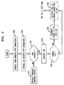
- FIG. 2 shows an illustrative high-level flow chart of a method in accordance with the principles of the invention for providing a VPN service to a remote user located at PC 110.
- LAC 155 and the other respective servers are suitably programmed to carry out the below-described methods using conventional programming techniques, which, as such, will not be described herein.
- PPP Point-to-Point Protocol
- LAC 155 partially authenticates the user (e.g., using a predefined "username” and "password") and accepts the connection (represented by dotted line 1 of FIG. 1).
- DNIS dialed number identification service
- CLID calling line identification
- PPP LCP Link Control Protocol
- the Serving LAC completes both the PPP LCP and PPP PAP/CHAP phases, as known in the art, with the user's equipment before initiating any communication with an LNS server in accordance with the inventive concept.
- PAP Password Authentication Protocol
- CHAP Challenge-Handshake Authentication Protocol
- LAC 155 determines if the remote user desires to use a VPN service. (This selection could, e.g., be directly associated with particular "usernames" and/or be associated with a separate request from the user, e.g., via a pop-up "HyperText Transport Protocol" (http) form provided by LAC 155.) If the remote user does not request a virtual dial-up service, LAC 155 provides standard Internet access in step 220. However, if the remote user desires to use a VPN, then LAC 155 identifies an associated LNS in step 225 (described below).
- LAC 155 stores a VPN table that a priori associates, e.g., a user's identification with a particular LNS. A portion of such a table is shown below in Table One.
- the remote user associated with PC 110 is associated with LNS 135, having an Internet Protocol (IP) address illustratively represented by the nomenclature "g.h.i.j.”
- IP Internet Protocol
- the Serving LAC may also perform this function via Radius Access Request/Response messages with a Home Radius Server.
- LAC 155 checks to see if a tunnel exists between itself and LNS 135. As such, LAC 155 maintains a table, as illustrated in Table Two, below, of current tunnels, represented by a tunnel identification (Tid) value, associated call identifiers (Cid) of calls currently using that tunnel, and the associated LNS IP address.
- LAC 155 If no tunnel connection currently exists between the LAC 155 and LNS 135, then a tunnel is negotiated in step 235 in accordance with the inventive concept (described below).
- LAC 155 in step 240, LAC 155 performs call admission control (described below) and, if the call is accepted, allocates a new Cid , updates Table Two, and initiates a session with LNS 135 by forwarding a VPN request to LNS 135 via local network 160, router 165, and Internet 130.
- LAC 155 conveys user identification information to LNS 135. (If the call not accepted, the incoming call is disconnected.)
- LNS 135 receives the request in step 305.
- LNS 135 accepts the PPP connection (at least for the moment).
- LNS 135 performs authentication of the remote user (e.g., using a predefined "username” and "password” as noted above). (Alternatively, like the Serving LAC, DNIS, CLID, or other equivalent forms of identification could be used.) If LNS 135 can not authenticate the user, the connection is not accepted and LNS 135 denies the request in step 320.
- LAC 155 similarly must convey an error message back to the remote user (not shown).
- LNS 135 accepts the connection (represented by dotted line 2 of FIG. 1) and establishes the VPN session in step 330.
- the VPN session with LNS 135 is established as in the prior art.
- the Serving LAC maintains the following connection table for each direction of communication for each established VPN session with a remote user: Connection # Serving LAC IP Address LNS LNS IP Address User Assigned IP Address Tid Cid 5 d.e.f.g 1 3 g.h.i.j a.b.c.d
- This table lists, by connection number, the Serving LAC IP Address, the associated LNS IP Address (with associated tunnel ID and Call ID values for that associated hop), and the user assigned IP address for this call.
- LAC 155 allocates a new Cid and updates Table Three (e.g., adds a new connection).
- the connectivity is a point-to-point PPP session whose endpoints are the remote user's networking application on one end (as represented by PC 110) and the termination of this connectivity into LNS 135 PPP support on the other.
- endpoints are the remote user's networking application on one end (as represented by PC 110) and the termination of this connectivity into LNS 135 PPP support on the other.
- accounting if necessary, can be performed at the Serving LAC, as well as the LNS, i.e., each element may count packets, octets and connection start and stop times.
- L2TP L2TP
- control messages between each LAC-LNS pair, and payload packets between the same LAC-LNS pair.
- the latter are used to transport mL2TP encapsulated PPP packets for user sessions between the LAC-LNS pair.
- Nr Next Received
- Ns Next Sent
- the control messages and payload messages use different sequence number states.
- a tunnel is negotiated as shown in step 235 of FIG. 2 to provide a particular QoS.
- mL2TP control messages are exchanged between the Serving LAC and the LNS.
- new Attribute Value Pairs (AVP)s are defined for use in the L2TP control messages (hence becoming mL2TP control messages) for enabling two mL2TP peers to set up, or negotiate, tunnels with different quality of service requirements.
- AVP Attribute Value Pairs
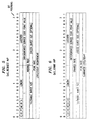
- FIG. 4 An illustrative control message transaction for performing tunnel negotiation is shown in FIG. 4 between two mL2TP peers (here represented by an LAC and an LNS). (Again, other than the inclusion of the new AVPs, these control message transactions are specified in L2TP.)
- the LAC in this context, also referred to herein as the "tunnel initiator" transmits a Start Control Connection Request (SCCRQ) message that now includes a QoS_Req AVP (described below) to the LNS (in this context, also referred to herein as the "tunnel terminator").
- SCCRQ Start Control Connection Request
- the LNS sends a Start Control Connection Reply (SCCRP) message that now includes a QoS_Grant AVP (described below) to the LAC.
- SCCRP Start Control Connection Reply
- the LAC confirms with a Start-Control-Connection-Connect (SCCCN) message to the LNS.
- FIG. 5 an illustrative format of a QoS_Req AVP is shown.
- the first two bits of this AVP have a predefined bit pattern of "10" (as defined L2TP), bit positions, 2 through 5, convey values for new parameters P, M, D, and L, where P is representative of a promotable bit, M is representative of a demotable bit, D is representative of a delay class bit, and L is representative of a Loss class.
- P is representative of a promotable bit
- M is representative of a demotable bit
- D is representative of a delay class bit
- L is representative of a Loss class.
- the D bit is used if the requested tunnel will support delay classes only. In other words, if the D bit is set in an SSCRQ message, only the delay bits of the differentiated code point value are taken into consideration (described below).
- the L bit is used if the requested tunnel will support loss classes only, i.e., if the L bit is set in a tunnel set up message (SSCRQ), only the loss bits of the code point are taken into consideration.
- the P and M bits are used on a per-call basis and ignored during tunnel negotiation.
- the mL2TP peer is indicating that only the chosen differentiated code point value is to be used on IP packets within the session's data channel.
- the P bit is set, it means that the mL2TP peer can recommend a differentiated service code point value with a higher level of service if the requested one is not available for a call.
- the mL2TP peer can recommend a differentiated service code point value with a lower level of service should the requested one not be available for a call.
- differentiated services can be offered by ISPs. For example, a user can buy a service where he pays y dollars for delay priority class 1 and x dollars for delay priority class 2 ($ y > $ x ). Every time the user places a call, the mL2TP peer determines if there are sufficient resources within a tunnel providing delay priority class 2 to admit the user's request. If there are insufficient resources, the mL2TP peer can promote the code point to the next higher level (i.e. try to see if there are sufficient resources to place the user's request in another tunnel providing delay priority class 1).
- a ten bit length field Following the P, M, D, and L bits is a ten bit length field, the value for which is the size of this AVP.
- the length field there is a two byte Vendor specific ID (here illustratively shown as conveying the data representative of a Lucent identifier (Lucentid) and denoting that this is a tunnel QoS message). (Alternatively, this could be replaced by a predefined mL2TP AVP code signifying that this is a tunnel QoS message.)
- the Vendor specific ID is followed by a two byte L2TP attribute type field, here set to 1.
- the attribute type field there is a differentiated services code point value (two bytes in length), which is used by the mL2TP peer (here the LNS) to indicate that it wishes to set up a tunnel supporting a particular class of differentiated service.
- the values of the differentiated service code point values are defined in a fashion similar to the definition of codepoints in the above-mentioned Assured Forwarding (AF) Service.
- the two mL2TP peers may set up classes of tunnels A if , where represents a type of delay class and j represents a type of loss class.
- there are 4 classes of tunnels each supporting a different delay priority class, i.e., with differentiated service code points Aix, I 1, 2, 3, 4, as shown in the table, below.
- the "X" represents a "don't care” condition, i.e., the value can be a binary zero or a binary one.
- the hyphen between the two bytes is to improve readability only. Individual sessions with differentiated service code points Aij are mapped to a tunnel supporting differentiated service code point Aix.
- the two L2TP peers may set up one tunnel specifically for differentiated service code point Aij and admit only individual sessions that request differentiated service code point Aij .
- differentiated service code point values such as 001xxx or xxx010 are acceptable for the tunnels.
- the two mL2TP peers specify a rate for each tunnel that supports AF services.
- the L2TP peers can decide when to admit/reject data sessions. They can also decide how to share the available resources (bandwidth and buffers) among the different established tunnels.
- the QoS_ Req AVP includes the EF Code Point (i.e., the differentiated service code point value), and the requested average rate.
- the average rate field, tolerable burst size field, excess burst size field, peak rate field and loss/delay requirement field represent traffic parameters that are used to provide tunnels with quantitative delay/loss guarantees as well as improve call admission probability (increase bandwidth multiplexing).
- the average rate field value represents the requested average bits per second for the tunnel.
- the tolerable burst size field value request represents how long a transmitter may transmit packets at the peak rate.
- the excess burst size (optional) field value request represents how long a transmitter can exceed the tolerable burst size.
- the peak field value request represents the requested peak rate, e.g., in bits per second.
- the loss/delay requirement field value request represents either packet loss (above-mentioned L bit field is set) or delay class (above-mentioned D bit field is set).
- packet loss this value represents the percentage of tolerable packet loss, e.g., 1%, 5%, etc.
- delay class this value represents the tolerable delay, e.g., in milli-seconds.
- bandwidth management is constrained.
- Rg Rg ⁇ (R1 + R2) and Rg >r 1 + r 2 , where r 1 and r 2 are the average rates for data sessions one and two, respectively.
- FIG. 6 shows an illustrative format for a QoS_Grant AVP sent by a tunnel terminator (e.g., LNS 135 of FIG. 1) in the SCCRP message.
- the fields of the QoS_Grant AVP are complementary to those of the QoS_Request AVP (described above).
- the responding server indicates the "Granted Rate” and the Guarantee Loss/Delay value.
- the granted rate may be smaller than the requested rate.
- the tunnel terminator can include in the SCCRP another QoS_Req AVP for reverse traffic if there is such a need.
- the reply from the tunnel initiator is contained in the QoS_Grant AVP within an SCCCN message.
- tunnel tuning process The process of renegotiating traffic parameters for existing tunnels is referred to herein as the tunnel tuning process.
- some pre-configured tunnels may need to be torn down and existing data sessions (supported on such tunnels) moved to another tunnel. This process is referred to herein as tunnel reassignment. Note that ideally, these two processes should happen only rarely. As such, and in accordance with the inventive concept, new L2TP messages are available for re-negotiating, or tuning, an existing tunnel.
- These new L2TP messages are "tunnel update” and "update confirm.”
- a "tunnel update” message is used by one mL2TP peer to inform the other mL2TP peer of new requested traffic parameters for an existing tunnel.
- the other mL2TP peer replies using the "update confirm” message.
- the "tunnel update” and “update confirm” messages use the same format as the QoS-Request and QoS-Grant AVPs, respectively, and, as such, are not shown herein.
- FIG. 7 An illustrative format for a new tunnel reassignment message is shown in FIG. 7. Like the "tunnel update" message, a tunnel reassignment message is only used if one chooses to support the tunnel tuning/re-negotiation mechanism. This message is used by one mL2TP peer to inform the other mL2TP peer that a particular data session has been moved to another tunnel. This mL2TP message includes the tunnel id (old or existing), the call id (old or existing), the new tunnel id, and new call id. Bit positions T and L are as defined L2TP.
- the LAC or LNS receives requests for setting up an incoming from a user or outgoing call to a user.
- the LAC or LNS determines the relevant traffic parameters and QoS (codepoints) based on the user's a priori defined profile.
- the LAC or LNS communicates with an Authentication Authorization and Accounting (AAA) server, as known in the art, to obtain such parameters based on user login name. For example, a user may buy a virtual lease line service (with an EF codepoint) of a particular rate.
- AAA Authentication Authorization and Accounting
- the traffic parameters specified for each individual session e.g., average rate, tolerable/excess burst sizes, peak rates, etc. are used for admission control purposes.
- Such information allows different mL2TP peers to keep track of the resources available for a tunnel supporting a particular class of service.
- a QoS_ Req AVP exists in the Incoming-Call-Request (ICRQ) or Outgoing-Call-Request (OCRQ) message.
- An QoS_Grant AVP is then present in the corresponding Incoming-Call-Reply (ICRP) and Outgoing-Call-Reply (OCRP) message.
- a QoS_ Req AVP for the reverse direction may also be present in the ICRP and OCRP messages. If a QoS_ Req AVP is present in the ICRP and OCRP messages, then a QoS_Grant AVP is present in the Incoming-Call-Connected (ICCN) and Outgoing-Call-Connected (OCCN) messages.
- ICCN Incoming-Call-Connected
- OCCN Outgoing-Call-Connected
- the mL2TP peer cannot accept that code point due to a shortage of resources, that mL2TP peer can recommend an alternative code point if the above-mentioned Promotable/Demotable bits are set. Otherwise, the mL2TP peer rejects the call request. Thus, the value found in the QoS_Grant AVP indicates the value that the mL2TP peer is willing to accept.
- d (b + C)/R + D , where d is the delay requested by a new call (or session), b is the burst size, R is the reserved bandwidth for the tunnel, and C and D are parameters defined as follows.
- the fluid delay of a flow obeying a traffic description ( r, b ), where r is the average rate and b is the burst size) and being served by a line with bandwidth R is bounded by b/R as long as R is no less than r .
- C and D which describe the maximum deviation away from the fluid model. For example, if the maximum transfer unit (MTU) size is 512 bytes, and the value of b is 1500 bytes, then C is equal to: 3 x 512, or 1500 bytes since an integer number of packets must be processed.
- MTU maximum transfer unit
- D needs to be large enough to account for the time a datagram may lose during the gap in service (e.g., D is expressed in milli-seconds)
- tunnels are ordered in increasing order of the delay they can guarantee (e.g., in a table such as that shown in Table Two, above) and that each tunnel is configured with parameters ( b T , R T , C T , D T ) where b T is the tolerable burst size, R T is the total reserved bandwidth for the tunnel, C T and D T are adjustments due to the packet nature and the superscript T is the tunnel id.
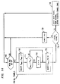
- FIG. 10 shows a generic flow chart of as call admission control algorithm.
- LNS 155 of FIG. 1 performs this call admission control algorithm. (However, either the LAC or the LNS can do it.)
- Step 705 of FIG. 10 represents the start of the process.
- LNS 155 executes step 710.
- LNS 155 maintains a table of tunnels (which are candidates for the incoming call) arranged in increasing order of delay.
- LNC 155 selects a set of "feasible tunnels.” That is, those tunnels for which Re ⁇ 0 , B new ⁇ B T / i and d T / i ⁇ d .
- LNC 155 picks that tunnel from the set of feasible tunnels that gives the minimum Re . If there is more than one such tunnel, LNC 155 picks the tunnel that also gives the smallest Be . This approach provides "maximal packing" of calls into a tunnel.
- LNC 155 can "minimally pack" calls into a tunnel. In this case, in step 740, LNC 155 picks that tunnel from the set of feasible tunnels that gives the maximum Re . If there is more than one such tunnel, LNC 155 picks the tunnel that also gives the largest Be .
- LNC 155 can admit calls into a tunnel in accordance with a "minimum bandwidth" approach. In this case, in step 740, LNC 155 picks that tunnel from the set of feasible tunnels that gives the smallest ⁇ . If there is more than one such tunnel, LNC 155 picks the tunnel that also gives the smallest Re .
- tunnels are ordered in increasing order of the loss probability they can guarantee (e.g., in a table such as that shown in Table Two, above) and that each tunnel is configured with parameters ( b T , R T , PL T ), where b T is the tolerable burst size, R T is the average reserved bandwidth for the tunnel, and PL T is the loss probability that the tunnel can guarantee.
- R f(b,r,p,pl), where f is a function that gives the bandwidth that needs to be reserved to ensure a loss probability of pl given a traffic with peak rate p , average rate r , and burst size b.
- f is a function that gives the bandwidth that needs to be reserved to ensure a loss probability of pl given a traffic with peak rate p , average rate r , and burst size b.
- step 705 of FIG. 11 represents the start of the process.
- LNS 155 executes step 710.
- LNS 155 maintains a table of tunnels (which are candidates for the incoming call) arranged in increasing order of the loss probability they can guarantee.
- step 715 LNS 155 checks if new bandwidth, R new,i , is smaller than the sum of the average rate for all tunnels, R o,i , and r .
- LNC 155 selects a set of "feasible tunnels.” That is, those tunnels for which Re ⁇ 0 ,B new ⁇ B T / i , and P T / i ⁇ pl .
- LNC 155 picks that tunnel from the set of feasible tunnels that gives the minimum Re . If there is more than one such tunnel, LNC 155 picks the tunnel that also gives the smallest Be . This approach provides "maximal packing" of calls into a tunnel.
- LNC 155 can admit calls into a tunnel in accordance with a "minimum bandwidth" approach. In this case, in step 740, LNC 155 picks that tunnel from the set of feasible tunnels that gives the smallest ⁇ . If there is more than one such tunnel, LNC 155 picks the tunnel that also gives the smallest Re .
- An NAS is a stored-program-control based processor architecture and includes processor 650, memory 660 (for storing program instructions and data, e.g., for communicating the above-mentioned new AVP messages related to QoS, etc.) and communications interface(s) 665 for coupling to one or more communication facilities as represented by path 666.
- processor 650 for storing program instructions and data, e.g., for communicating the above-mentioned new AVP messages related to QoS, etc.
- communications interface(s) 665 for coupling to one or more communication facilities as represented by path 666.
- inventive concept was described in the context of a Serving LAC tunneling to an LNS, the inventive concept is applicable to multi-hop tunnels, e.g., such as described in the co-pending and commonly assigned U.S. Patent application of Chuah et al., entitled “A Multi-Hop Point-to-Point Protocol,” serial No. 09/074745, filed on May 5, 1998.
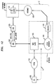
- FIG. 12 The communications system of FIG. 12 is similar to FIG. 1 except that the NAS and the NS each communicate with an AAA server.
- the corresponding AAA servers then negotiate tunnel QoS using the above-described, suitably modified AVPs.
Landscapes
- Engineering & Computer Science (AREA)
- Computer Networks & Wireless Communication (AREA)
- Signal Processing (AREA)
- Computer Security & Cryptography (AREA)
- Data Exchanges In Wide-Area Networks (AREA)
- Communication Control (AREA)
- Telephonic Communication Services (AREA)
- Small-Scale Networks (AREA)
Applications Claiming Priority (2)
| Application Number | Priority Date | Filing Date | Title |
|---|---|---|---|
| US25990099A | 1999-02-26 | 1999-02-26 | |
| US259900 | 1999-02-26 |
Publications (2)
| Publication Number | Publication Date |
|---|---|
| EP1043869A2 true EP1043869A2 (de) | 2000-10-11 |
| EP1043869A3 EP1043869A3 (de) | 2003-12-10 |
Family
ID=22986910
Family Applications (1)
| Application Number | Title | Priority Date | Filing Date |
|---|---|---|---|
| EP00301162A Withdrawn EP1043869A3 (de) | 1999-02-26 | 2000-02-15 | Bereitstellung von Dienstqualität in L2TP (Layer Two Tunneling Protocol) Netzen |
Country Status (4)
| Country | Link |
|---|---|
| EP (1) | EP1043869A3 (de) |
| JP (1) | JP2000253070A (de) |
| KR (1) | KR20000076720A (de) |
| MX (1) | MXPA00001931A (de) |
Cited By (8)
| Publication number | Priority date | Publication date | Assignee | Title |
|---|---|---|---|---|
| WO2008037397A1 (en) * | 2006-09-28 | 2008-04-03 | Koninklijke Kpn N.V. | Method and system for selecting a data transmission rate |
| US7389350B2 (en) * | 2001-03-05 | 2008-06-17 | International Business Machines Corporation | Method, apparatus and computer program product for integrating heterogeneous systems |
| CN100407721C (zh) * | 2002-10-24 | 2008-07-30 | 华为技术有限公司 | 基于二层隧道协议的网络服务器支持多实例的方法 |
| US7606201B2 (en) | 2005-04-25 | 2009-10-20 | Telefonaktiebolaget Lm Ericsson (Publ) | Handover enabler |
| CN104104661A (zh) * | 2013-04-09 | 2014-10-15 | 中兴通讯股份有限公司 | 客户端、服务器、远程用户拨号认证能力协商方法及系统 |
| US9197706B2 (en) | 2008-12-16 | 2015-11-24 | Qualcomm Incorporated | Apparatus and method for bundling application services with inbuilt connectivity management |
| US9288230B2 (en) | 2010-12-20 | 2016-03-15 | Qualcomm Incorporated | Methods and apparatus for providing or receiving data connectivity |
| EP3190743A4 (de) * | 2014-12-05 | 2017-09-06 | Huawei Technologies Co. Ltd. | Paketverarbeitungsverfahren, netzwerkserver und virtuelles privates netzwerksystem |
Families Citing this family (4)
| Publication number | Priority date | Publication date | Assignee | Title |
|---|---|---|---|---|
| KR100438431B1 (ko) * | 2002-02-23 | 2004-07-03 | 삼성전자주식회사 | 통신 네트워크에서 가상 사설 네트워크 서비스 접속을위한 보안 시스템 및 방법 |
| JP2007096617A (ja) * | 2005-09-28 | 2007-04-12 | Nec Corp | 携帯端末、携帯端末システム、携帯端末通信方法、携帯端末通信プログラム、該プログラムを記録した記録媒体 |
| JP4965149B2 (ja) * | 2006-03-31 | 2012-07-04 | 株式会社トプコン | Rtk−gps測位システム |
| US20100205099A1 (en) * | 2008-12-16 | 2010-08-12 | Kalle Ahmavaara | System and methods to facilitate connections to access networks |
-
2000
- 2000-02-15 EP EP00301162A patent/EP1043869A3/de not_active Withdrawn
- 2000-02-24 MX MXPA00001931A patent/MXPA00001931A/es unknown
- 2000-02-24 KR KR1020000008973A patent/KR20000076720A/ko not_active Ceased
- 2000-02-28 JP JP2000051868A patent/JP2000253070A/ja active Pending
Non-Patent Citations (2)
| Title |
|---|
| MATHY L ET AL: "QOS NEGOTIATION FOR MULTICAST COMMUNICATIONS" MULTIMEDIA TRANSPORT AND TELESERVICES. INTERNATIONAL COST 237 WORKSHOPPROCEEDINGS. VIENNA, NOV. 13 - 15, 1994, INTERNATIONAL COST 237 WORKSHOP PROCEEDINGS, BERLIN, SPRINGER, DE, 13 November 1994 (1994-11-13), pages 199-218, XP000585302 ISBN: 3-540-58759-4 * |
| PAT R. CALHOUN, KEN PEIRCE: "Layer Two Tunneling Protocol "L2TP" IP Differential Services Extension" PPP WORKING GROUP, INTERNET DRAFT, [Online] July 1998 (1998-07), XP002240056 Retrieved from the Internet: <URL:http://www.ietf.org/proceedings/98aug /I-D/draft-ietf-pppext-l2tp-ds-02.txt> [retrieved on 2003-05-05] * |
Cited By (11)
| Publication number | Priority date | Publication date | Assignee | Title |
|---|---|---|---|---|
| US7389350B2 (en) * | 2001-03-05 | 2008-06-17 | International Business Machines Corporation | Method, apparatus and computer program product for integrating heterogeneous systems |
| US7904567B2 (en) | 2001-03-05 | 2011-03-08 | International Business Machines Corporation | Method, apparatus and computer program product for integrating heterogeneous systems |
| US7925764B2 (en) | 2001-03-05 | 2011-04-12 | International Business Machines Corporation | Method, apparatus and computer program product for integrating heterogeneous systems |
| CN100407721C (zh) * | 2002-10-24 | 2008-07-30 | 华为技术有限公司 | 基于二层隧道协议的网络服务器支持多实例的方法 |
| US7606201B2 (en) | 2005-04-25 | 2009-10-20 | Telefonaktiebolaget Lm Ericsson (Publ) | Handover enabler |
| WO2008037397A1 (en) * | 2006-09-28 | 2008-04-03 | Koninklijke Kpn N.V. | Method and system for selecting a data transmission rate |
| US9197706B2 (en) | 2008-12-16 | 2015-11-24 | Qualcomm Incorporated | Apparatus and method for bundling application services with inbuilt connectivity management |
| US9288230B2 (en) | 2010-12-20 | 2016-03-15 | Qualcomm Incorporated | Methods and apparatus for providing or receiving data connectivity |
| CN104104661A (zh) * | 2013-04-09 | 2014-10-15 | 中兴通讯股份有限公司 | 客户端、服务器、远程用户拨号认证能力协商方法及系统 |
| US10250581B2 (en) | 2013-04-09 | 2019-04-02 | Zte Corporation | Client, server, radius capability negotiation method and system between client and server |
| EP3190743A4 (de) * | 2014-12-05 | 2017-09-06 | Huawei Technologies Co. Ltd. | Paketverarbeitungsverfahren, netzwerkserver und virtuelles privates netzwerksystem |
Also Published As
| Publication number | Publication date |
|---|---|
| JP2000253070A (ja) | 2000-09-14 |
| KR20000076720A (ko) | 2000-12-26 |
| MXPA00001931A (es) | 2002-03-08 |
| EP1043869A3 (de) | 2003-12-10 |
Similar Documents
| Publication | Publication Date | Title |
|---|---|---|
| US6654808B1 (en) | Proving quality of service in layer two tunneling protocol networks | |
| US7649890B2 (en) | Packet forwarding apparatus and communication bandwidth control method | |
| US6449272B1 (en) | Multi-hop point-to-point protocol | |
| US6917600B1 (en) | Mobile point-to-point protocol | |
| US6801509B1 (en) | Mobile point-to-point protocol | |
| US7225259B2 (en) | Service tunnel over a connectionless network | |
| EP1281255B1 (de) | Verfahren und System zum Senden von Informationen in einem externen Netzwerk | |
| EP2290905B1 (de) | Paketflussverarbeitung in einem Kommunikationssystem | |
| US6950862B1 (en) | System and method for offloading a computational service on a point-to-point communication link | |
| US7571238B1 (en) | Authorizing communication services | |
| KR20000076720A (ko) | 패킷 서버 내에서의 이용 방법 | |
| JP4189965B2 (ja) | 通信ノード | |
| AU2002233902B2 (en) | A method and apparatus for transferring data packets in communication networks | |
| Lee et al. | Service Provision for Future Access Networks Using PPP Extensions | |
| AU2002233902A1 (en) | A method and apparatus for transferring data packets in communication networks |
Legal Events
| Date | Code | Title | Description |
|---|---|---|---|
| PUAI | Public reference made under article 153(3) epc to a published international application that has entered the european phase |
Free format text: ORIGINAL CODE: 0009012 |
|
| AK | Designated contracting states |
Kind code of ref document: A2 Designated state(s): AT BE CH CY DE DK ES FI FR GB GR IE IT LI LU MC NL PT SE |
|
| AX | Request for extension of the european patent |
Free format text: AL;LT;LV;MK;RO;SI |
|
| PUAL | Search report despatched |
Free format text: ORIGINAL CODE: 0009013 |
|
| AK | Designated contracting states |
Kind code of ref document: A3 Designated state(s): AT BE CH CY DE DK ES FI FR GB GR IE IT LI LU MC NL PT SE |
|
| AX | Request for extension of the european patent |
Extension state: AL LT LV MK RO SI |
|
| AKX | Designation fees paid | ||
| REG | Reference to a national code |
Ref country code: DE Ref legal event code: 8566 |
|
| STAA | Information on the status of an ep patent application or granted ep patent |
Free format text: STATUS: THE APPLICATION IS DEEMED TO BE WITHDRAWN |
|
| 18D | Application deemed to be withdrawn |
Effective date: 20040901 |