EP1044665A2 - Blattartiger Schaft einer Hüftgelenkprothese für die Verankerung im Femur - Google Patents
Blattartiger Schaft einer Hüftgelenkprothese für die Verankerung im Femur Download PDFInfo
- Publication number
- EP1044665A2 EP1044665A2 EP00107892A EP00107892A EP1044665A2 EP 1044665 A2 EP1044665 A2 EP 1044665A2 EP 00107892 A EP00107892 A EP 00107892A EP 00107892 A EP00107892 A EP 00107892A EP 1044665 A2 EP1044665 A2 EP 1044665A2
- Authority
- EP
- European Patent Office
- Prior art keywords
- anchoring section
- femur
- shaft according
- anchoring
- shaft
- Prior art date
- Legal status (The legal status is an assumption and is not a legal conclusion. Google has not performed a legal analysis and makes no representation as to the accuracy of the status listed.)
- Granted
Links
Images


Classifications
-
- A—HUMAN NECESSITIES
- A61—MEDICAL OR VETERINARY SCIENCE; HYGIENE
- A61F—FILTERS IMPLANTABLE INTO BLOOD VESSELS; PROSTHESES; DEVICES PROVIDING PATENCY TO, OR PREVENTING COLLAPSING OF, TUBULAR STRUCTURES OF THE BODY, e.g. STENTS; ORTHOPAEDIC, NURSING OR CONTRACEPTIVE DEVICES; FOMENTATION; TREATMENT OR PROTECTION OF EYES OR EARS; BANDAGES, DRESSINGS OR ABSORBENT PADS; FIRST-AID KITS
- A61F2/00—Filters implantable into blood vessels; Prostheses, i.e. artificial substitutes or replacements for parts of the body; Appliances for connecting them with the body; Devices providing patency to, or preventing collapsing of, tubular structures of the body, e.g. stents
- A61F2/02—Prostheses implantable into the body
- A61F2/30—Joints
- A61F2/32—Joints for the hip
- A61F2/36—Femoral heads ; Femoral endoprostheses
- A61F2/3662—Femoral shafts
-
- A—HUMAN NECESSITIES
- A61—MEDICAL OR VETERINARY SCIENCE; HYGIENE
- A61F—FILTERS IMPLANTABLE INTO BLOOD VESSELS; PROSTHESES; DEVICES PROVIDING PATENCY TO, OR PREVENTING COLLAPSING OF, TUBULAR STRUCTURES OF THE BODY, e.g. STENTS; ORTHOPAEDIC, NURSING OR CONTRACEPTIVE DEVICES; FOMENTATION; TREATMENT OR PROTECTION OF EYES OR EARS; BANDAGES, DRESSINGS OR ABSORBENT PADS; FIRST-AID KITS
- A61F2/00—Filters implantable into blood vessels; Prostheses, i.e. artificial substitutes or replacements for parts of the body; Appliances for connecting them with the body; Devices providing patency to, or preventing collapsing of, tubular structures of the body, e.g. stents
- A61F2/02—Prostheses implantable into the body
- A61F2/30—Joints
- A61F2002/30001—Additional features of subject-matter classified in A61F2/28, A61F2/30 and subgroups thereof
- A61F2002/30316—The prosthesis having different structural features at different locations within the same prosthesis; Connections between prosthetic parts; Special structural features of bone or joint prostheses not otherwise provided for
- A61F2002/30535—Special structural features of bone or joint prostheses not otherwise provided for
-
- A—HUMAN NECESSITIES
- A61—MEDICAL OR VETERINARY SCIENCE; HYGIENE
- A61F—FILTERS IMPLANTABLE INTO BLOOD VESSELS; PROSTHESES; DEVICES PROVIDING PATENCY TO, OR PREVENTING COLLAPSING OF, TUBULAR STRUCTURES OF THE BODY, e.g. STENTS; ORTHOPAEDIC, NURSING OR CONTRACEPTIVE DEVICES; FOMENTATION; TREATMENT OR PROTECTION OF EYES OR EARS; BANDAGES, DRESSINGS OR ABSORBENT PADS; FIRST-AID KITS
- A61F2250/00—Special features of prostheses classified in groups A61F2/00 - A61F2/26 or A61F2/82 or A61F9/00 or A61F11/00 or subgroups thereof
- A61F2250/0058—Additional features; Implant or prostheses properties not otherwise provided for
Definitions
- the invention relates to a sheet-like shaft Hip prosthesis for anchoring in the femur with a Femur anchoring section and a prosthetic neck.
- EP 0 427 902 B1 proposes a section of the Execute the shaft with contact surfaces provided with saw teeth. This should allow the shaft to grow into the Bone substance can be improved.
- the present invention is based on the object Femur anchoring section of a leaf-like shaft so too shape that the tissue growing on the prosthesis if possible consists largely of cancellous bone tissue, so that a firm hold of the shaft in the femur is permanently guaranteed.
- the revascularization of the bone tissue additionally promoted, namely under Maintaining the necessary stability or strength of the Shank on the one hand, but with enlargement of the space between the shaft and the surgical cavity on the other hand with the result of increased training of new cancellous bone.
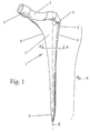
- Fig. 1 shows a perspective view of a leaf-like Shaft 1 of a hip prosthesis for anchoring in the femur.
- the embodiment shown comprises one of one distal end 5 from widening conically on all sides Anchoring section 1a, ... 1i (see Fig. 2 to 10), the in the proximal area on the medial side into a steady curved arc 8 passes.
- This arch 8 sits in one Denture neck 2 continued; there is a conical taper on them Pin 3 placed on a spherical joint head records.
- the prosthesis neck axis intersects the (in Fig. 1 not shown) longitudinal central axis of the shaft or anchoring section 1a ... 1i at an angle that in essentially the angle between the femoral neck and the Femur axis corresponds to a natural hip joint.
- a trochanter wing 4 is formed laterally in the proximal region of the shaft 1 and is laterally delimited by a side surface 9.
- the transition between the lateral surface on the one hand and the posterior or anterior surface on the other hand is defined by an oblique edge 6 which extends from distal to proximal in the region of the trochanter wing 4.
- the Blade "of the shaft 1 is defined in the proximal region and is identified by the reference number 7.
- 2 - 10 are different cross sections or Profile shapes of anchoring sections 1a ... 1i des Shaft 1 shown.
- the anchoring section 1 a is an oblique cross profile trained, with the legs anterior and posterior each have a V-shaped groove 11a, 11b with an angle greater than 90 ° and laterally and medially with a V-shaped groove 12a, 12b form an angle of less than 90 °.
- This Profile includes rectangular recesses 13a, 13b on the posterior and anterior side.
- Fig. 4 shows a further variant in which the anchoring section 1c of the shaft 1 is a double H profile or double comb profile is with the formation of rectangular longitudinal grooves 14a, 14b, 14c, 14d on the posterior and anterior side of the Anchoring section.
- Fig. 5 is the anchoring section 1d of the shaft 1 in the rough cross-sectional shape rectangular, with hollow facets formed on the four edges.
- FIGS. 6 and 7 show one Anchoring section 1e or 1f in the form of a rectangular hollow profile, 6 in the embodiment according to FIG Cross section of the cavity 15 is rectangular, while at 7 the cross section of the cavity 16 is elliptical. These two variants are characterized by a particularly high stability of the anchoring section on the one hand and light weight on the other.
- the variant according to FIG. 8 shows an anchoring section 1g, which is defined by a rectangular notch profile. Are there posterior and anterior two spaced apart Longitudinal notches 17a, 17b and 17c, 17d formed. It is about each by V-notches. Lateral and medial are one Longitudinal notch 18a, 18b provided, also V-shaped Notches or longitudinal grooves.
- the edges bounding the outline of the anchoring section 1g can, just as in the case of Embodiment according to FIGS. 6 and 7 each flat or Have hollow facets corresponding to FIG. 5.
- the rectangular cavity 15 still be divided by one in the longitudinal direction of the shaft extending web or cross web.
- the embodiment according to FIG. 8 can be like the one according to FIG 5 be designed as a hollow profile with a Longitudinal cavity extending cavity, the cross section is circular or oval or elliptical.
- FIG. 9 1h differs from that shown in Figures 2-8 Executions by a trapezoidal cross-sectional shape, the here symmetrical with two equally long side edges a, those in cross section the anterior or posterior Limit sides and two different lengths shorter side edges b, c, of which the shorter medial and the longer that comes to lie laterally is shown.
- This symmetrical trapezoidal shape is currently considered the preferred viewed, but are also generally asymmetrical trapezoidal Prosthetic socket cross-sections are possible.
- FIGS. 2-8 modifications of the cross-sectional shapes shown in FIGS. 2-8 (which are, as it were, inscribed in a rectangle in these figures) can also be carried out, for example an asymmetrical diagonal cross H "with a longer and a shorter leg, an embodiment similar to FIG. 4 with three legs of different lengths, an embodiment corresponding to the embodiment according to FIG. 5 with hollow facets in the edge regions of a trapezoidal cross section or various hollow profiles with a trapezoidal outer shape.
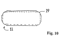
- Fig. 10 is to show another special Execution of the anchoring section of the invention
- Shaft prosthesis shown a cross-sectional shape, which in turn is based on the basic shape of a rectangle and on all edges has stepped chamfer areas 19.
- This embodiment is based on the idea that with a prosthesis socket - at least in the proximal area - a predetermined excess compared to the dimensions of the prepared femoral cavity (ie compared to the Rasp size ”) is advantageous in that it increases the surface pressure compared to the surrounding bone tissue and thereby brings about a certain amount of bone compression.
- the excess is, also in view of the usual forging accuracy, about 1-3%, based on that as well Rasp size to be understood in the medullary canal.
- a stepped edge shape shown in Fig. 10 The resulting re-milling has proven to be relatively easy to implement and proven to be effective in an advantageous manner; basically other fine structures in the edge area are also possible, with which the dimensional accuracy of the edges (more precisely: the Chamfer) is reconciled with an excess of remaining side and end faces - for example Rounding or additional, compared to the actual chamfer inclined chamfers.
Landscapes
- Health & Medical Sciences (AREA)
- Orthopedic Medicine & Surgery (AREA)
- Cardiology (AREA)
- Oral & Maxillofacial Surgery (AREA)
- Transplantation (AREA)
- Engineering & Computer Science (AREA)
- Biomedical Technology (AREA)
- Heart & Thoracic Surgery (AREA)
- Vascular Medicine (AREA)
- Life Sciences & Earth Sciences (AREA)
- Animal Behavior & Ethology (AREA)
- General Health & Medical Sciences (AREA)
- Public Health (AREA)
- Veterinary Medicine (AREA)
- Prostheses (AREA)
Abstract
Description
- Schrägkreuzprofil
- H-Profil
- Doppel-H- bzw. -Kammprofil
- Rechteck-Hohlprofil
- Rechteck-Facettenprofil
- Rechteck-Kerbprofil
- annähernd trapezförmiges Profil (mit oder ohne Ausnehmungen an den Seiten oder im Innern)
- oder dergleichen.
- Fig. 1
- eine perspektivische Ansicht eines blattartigen Schaftes, dessen Femur-Verankerungsabschnitt erfindungsgemäß weitergebildet wird;
- Fig. 2 - 9
- verschiedene Querschnitte des Verankerungsabschnittes des Schaftes gemäß Fig. 1 längs der Linie A-A in Fig. 1, und
- Fig. 10
- eine weitere bevorzugte Ausführung in Querschnittsdarstellung.
- 1
- Schaft
- 1a, 1b, 1c, 1d, 1e, 1f, 1g, 1h, 1i
- Femur-Verankerungsabschnitt
- 2
- Prothesenhals
- 3
- kegelstumpfförmiger Zapfen
- 4
- Trochanterflügel
- 5
- distales Ende
- 6
- Facette
- 7
- Abschnitt des Schaftes
- 8
- Bogen
- 9
- laterale Begrenzung
- 11a, 11b
- V-Nut
- 12a, 12b
- V-Nut
- 13a, 13b
- Rechteck-Nut
- 14a, 14b, 14c, 14d
- Rechteck-Nut
- 15
- rechteckiger Hohlraum
- 16
- ovaler Hohlraum
- 17a, 17b, 17c, 17d, 18a, 18b
- Längskerbe
- 19
- abgestufte Anfasung
- a
- Längsseite
- b, c
- Stirnseite
Claims (9)
- Blattartiger Schaft (1) einer Hüftgelenkprothese für die Verankerung im Femur, mit einem sich zu einem distalen Ende (5) hin verjüngenden Femur-Verankerungsabschnitt (1a, ... 1i) mit einer Längsachse (A) sowie einem Prothesenhals (2),
dadurch gekennzeichnet,
daß der Femur-Verankerungsabschnitt (1a, ... 1i) in einer Ebene senkrecht zur Längsachse (A) im wesentlichen eine viereckige Außenkontur, wahlweise mit Ausnehmungen in den Seitenkanten und/oder an den Ecken und/oder im Inneren, hat. - Schaft nach Anspruch 1,
dadurch gekennzeichnet,
daß der Verankerungsabschnitt (1a) in der Ebene senkrecht zur Längsachse (A) als Schrägkreuz derart ausgebildet ist, daß vier Schenkel eines Kreuzes (Fig.2) anterior und posterior je eine V-förmige Nut (11a, 11b) mit einem Öffnungswinkel von mehr als 90° und lateral und medial jeweils eine V-förmige Nut (12a, 12b) mit einem Öffnungswinkel von weniger als 90° bilden. - Schaft nach Anspruch 1,
dadurch gekennzeichnet,
daß der Verankerungsabschnittes (1d - 1g; 1i) in einer Ebene senkrecht zur Längsachse (A) im wesentlichen die Form eines Rechtecks, mit Ausschnitten im Bereich mindestens einer Seitenkante und/oder der Ecken und/oder im Inneren, hat. - Schaft nach Anspruch 1,
dadurch gekennzeichnet,
daß der Verankerungsabschnitt (1h) in einer Ebene senkrecht zur Längsachse (A) im wesentlichen die Form eines Trapezes, insbesondere mit Ausschnitten im Bereich mindestens einer Seitenkante und/oder der Ecken und/oder im Inneren, hat. - Schaft nach Anspruch 4,
dadurch gekennzeichnet,
daß die Gestalt des Trapezes im wesentlichen symmetrisch ist, wobei die anteriore und posteriore Seitenkante des Trapezes gleich lang und länger als die laterale und mediale Seitenkante sind, von denen die mediale Seitenkante die kürzere ist. - Schaft nach einem der Ansprüche 1 oder 3 - 5,
dadurch gekennzeichnet,
daß ein durch eine Ausnehmung im Inneren definierter Hohlraum (15; 16) des Verankerungsabschnittes (1e; 1f) im wesentlichen der Außenkontur des Verankerungsabschnittes angepaßt rechteckig oder trapezförmig oder aber kreisförmig oder elliptisch ausgebildet ist. - Schaft nach einem der Ansprüche 3 - 5,
dadurch gekennzeichnet,
daß in den die posteriore und anteriore Seitenfläche bestimmenden Seitenkanten jeweils zwei oder mehr im wesentlichen V-, U- oder C-förmige Ausnehmungen (17a - 17d) ausgebildet sind und insbesondere auch in den die laterale und/oder mediale Stirnfläche bestimmenden Begrenzungskanten jeweils wenigstens eine V-, U- oder C-förmige Ausnehmung (18a, 18b) ausgebildet ist. - Schaft nach Anspruch 1 oder einem der Ansprüche 3 - 7,
dadurch gekennzeichnet,
daß mindestens in einem der Längskantenbereiche des Verankerungsabschnittes (1i), bevorzugt in all seinen Längskantenbereichen, eine zu den benachbarten Seitenflächen hin abgestufte, zusätzlich abgewinkelte oder abgerundete Anfasung (19) vorgesehen ist und die verbleibenden Seitenflächenbereiche mindestens in einem proximalen Teilabschnitt der Längserstreckung des Verankerungsabschnitt ein Übermaß gegenüber einem bei der Präparation des Femurs verwendeten Raspelmaß aufweisen. - Schaft nach Anspruch 8,
dadurch gekennzeichnet,
daß das Übermaß im Bereich zwischen 1 und 3 % liegt, wobei der Verankerungsabschnitt im übermaßigen Bereich geschmiedet ist und der Anfasungsbereich oder die Anfasungsbereiche ausgefräst ist/sind.
Applications Claiming Priority (4)
| Application Number | Priority Date | Filing Date | Title |
|---|---|---|---|
| DE19916629 | 1999-04-13 | ||
| DE19916629 | 1999-04-13 | ||
| DE19928791A DE19928791A1 (de) | 1999-04-13 | 1999-06-23 | Blattartiger Schaft einer Hüftgelenkprothese für die Verankerung im Femur |
| DE19928791 | 1999-06-23 |
Publications (3)
| Publication Number | Publication Date |
|---|---|
| EP1044665A2 true EP1044665A2 (de) | 2000-10-18 |
| EP1044665A3 EP1044665A3 (de) | 2001-01-31 |
| EP1044665B1 EP1044665B1 (de) | 2005-11-02 |
Family
ID=26052886
Family Applications (1)
| Application Number | Title | Priority Date | Filing Date |
|---|---|---|---|
| EP00107892A Expired - Lifetime EP1044665B1 (de) | 1999-04-13 | 2000-04-12 | Blattartiger Schaft einer Hüftgelenkprothese für die Verankerung im Femur |
Country Status (5)
| Country | Link |
|---|---|
| US (4) | US6540788B1 (de) |
| EP (1) | EP1044665B1 (de) |
| AT (1) | ATE308290T1 (de) |
| DE (2) | DE19928791A1 (de) |
| ES (1) | ES2251904T3 (de) |
Cited By (7)
| Publication number | Priority date | Publication date | Assignee | Title |
|---|---|---|---|---|
| WO2004064688A1 (de) * | 2003-01-17 | 2004-08-05 | Waldemar Link Gmbh & Co. Kg | Hüftprothese mit einem in dem markkanal des oberschenkelknochens zu verankernden schaft |
| WO2004069102A1 (de) * | 2003-02-10 | 2004-08-19 | Waldemar Link Gmbh & Co. Kg | Hüftgfelenkprothese mit einem in den oberschenkelknochen einzusetzenden schaft |
| US6808539B2 (en) | 1999-04-13 | 2004-10-26 | Plus Endoprothetik Ag | Leaflike shaft of a hip-joint prosthesis for anchoring in the femur |
| WO2008046734A1 (de) * | 2006-10-19 | 2008-04-24 | Jacques Valloton | Endoprothese für ein hüftgelenk |
| US7494510B2 (en) | 2000-04-13 | 2009-02-24 | Smith And Nephew Orthopaedics Ag | Leaflike shaft of a hip-joint prosthesis for anchoring in the femur |
| US7914585B2 (en) | 2003-01-17 | 2011-03-29 | Waldemar Link Gmbh & Co. Kg | Hip prosthesis including a shaft to be inserted into the femur |
| US7947084B2 (en) | 2004-08-06 | 2011-05-24 | Waldemar Link Gmbh & Co. Kg | Hip joint prosthesis with a shaft to be inserted into the femur |
Families Citing this family (18)
| Publication number | Priority date | Publication date | Assignee | Title |
|---|---|---|---|---|
| WO2000059410A2 (de) * | 1999-04-07 | 2000-10-12 | Plus Endoprothetik Ag | Blattartiger schaft einer hüftgelenkprothese für die verankerung im femur |
| US6986792B2 (en) * | 2002-09-13 | 2006-01-17 | Smith & Nephew, Inc. | Prostheses |
| FR2867060B1 (fr) * | 2004-03-02 | 2007-07-06 | Medacta Int Sa | Implant femoral a aretes vives pour prothese de hanche |
| DE102004038281B3 (de) * | 2004-08-03 | 2006-05-11 | Endoplant Gmbh | Schenkelhalsprothese |
| GB2419291A (en) * | 2004-10-21 | 2006-04-26 | Biomet Uk Ltd | A femoral head prosthesis |
| JP2008531089A (ja) * | 2005-02-22 | 2008-08-14 | スミス アンド ネフュー インコーポレーテッド | ステムに使用する長尺スリーブ |
| DE102005048873A1 (de) * | 2005-09-20 | 2007-03-29 | Plus Orthopedics Ag | Blattartiger Schaft für Hüftgelenkprothese |
| JP5755445B2 (ja) * | 2007-07-11 | 2015-07-29 | スミス アンド ネフュー インコーポレーテッド | 股関節手術中にピン配置を決定するための方法及び装置 |
| US20090299485A1 (en) * | 2008-05-28 | 2009-12-03 | Emmanuel Michelinakis | Implant |
| RU2385693C1 (ru) * | 2008-10-06 | 2010-04-10 | Общество с ограниченной ответственностью "ИЛЬКОМ" | Ножка эндопротеза тазобедренного сустава |
| FR2946860B1 (fr) * | 2009-06-22 | 2011-08-26 | Amplitude | Tige femorale de revision |
| US8398719B2 (en) * | 2009-09-01 | 2013-03-19 | Concept, Design And Development, Llc | Neck sparing total hip implant methods |
| US8470049B2 (en) * | 2009-09-01 | 2013-06-25 | Concept, Design And Development, Llc | Neck sparing total hip implant system |
| US20120016486A1 (en) | 2010-06-08 | 2012-01-19 | Smith & Nephew, Inc. | Implant components and methods |
| CA2834937A1 (en) | 2011-05-03 | 2012-11-08 | Smith & Nephew, Inc. | Patient-matched guides for orthopedic implants |
| CA2858559C (en) | 2011-12-07 | 2021-04-20 | Smith & Nephew, Inc. | Orthopedic implant augments |
| JP6223997B2 (ja) | 2011-12-07 | 2017-11-01 | スミス アンド ネフュー インコーポレイテッド | 陥凹ポケットを有する整形外科増強物 |
| EP4501252A1 (de) | 2023-08-01 | 2025-02-05 | Smith & Nephew, Inc. | Orthopädisches räumwerkzeug |
Family Cites Families (55)
| Publication number | Priority date | Publication date | Assignee | Title |
|---|---|---|---|---|
| US3067740A (en) * | 1959-09-08 | 1962-12-11 | Edward J Haboush | Hip joint prosthesis |
| FR1287526A (fr) * | 1961-01-23 | 1962-03-16 | Prothèse de remplacement de l'articulation coxo-fémorale | |
| FR2315902A1 (fr) * | 1975-07-01 | 1977-01-28 | Ceraver | Tige metallique d'insertion dans un os long pour prothese |
| DE2627569C2 (de) * | 1976-06-19 | 1982-03-11 | Friedrichsfeld Gmbh, Steinzeug- Und Kunststoffwerke, 6800 Mannheim | Oberschenkelteil einer Hüftgelenkendoprothese |
| SE7710780L (sv) | 1977-02-14 | 1978-08-15 | Richards Mfg Co | Hoftledsprotes |
| CH622423A5 (de) * | 1977-10-12 | 1981-04-15 | Sulzer Ag | |
| CH640406A5 (de) | 1979-10-11 | 1984-01-13 | Sulzer Ag | Hueftgelenkprothese. |
| CH642252A5 (de) | 1980-01-14 | 1984-04-13 | Sulzer Ag | Blattartiger schaft fuer die verankerung einer hueftgelenkprothese. |
| DE3462303D1 (en) | 1983-08-29 | 1987-03-12 | Protek Ag | Stem for a hip joint prosthesis |
| CH662268A5 (de) * | 1984-03-06 | 1987-09-30 | Protek Ag | Hueftgelenkprothese. |
| DE3577974D1 (de) * | 1984-04-14 | 1990-07-05 | Howmedica Int Inc | Hueftgelenkendoprothese. |
| CH663149A5 (en) | 1984-05-21 | 1987-11-30 | Sulzer Ag | Stem for a hip joint prosthesis |
| CH669107A5 (de) | 1986-04-03 | 1989-02-28 | Sulzer Ag | Blattartiger schaft fuer die verankerung einer hueftgelenksprothese im femur. |
| CH669106A5 (de) | 1986-04-03 | 1989-02-28 | Sulzer Ag | Blattartiger schaft fuer die verankerung einer hueftgelenksprothese im femur. |
| DE3715000A1 (de) | 1987-05-06 | 1988-11-17 | Krupp Gmbh | Gelenkprothese und verfahren zu ihrer herstellung |
| DE8712607U1 (de) * | 1987-09-18 | 1989-01-19 | Howmedica GmbH, 2314 Schönkirchen | Oberschenkelteil einer Hüftgelenkendoprothese |
| US4865608A (en) | 1987-11-20 | 1989-09-12 | Brooker Jr Andrew F | Grooved endoprosthesis |
| DE3819948A1 (de) * | 1988-06-11 | 1989-12-14 | Orthoplant Endoprothetik | Einzementierbares oberschenkelteil einer hueftgelenk-endoprothese |
| FR2634642B1 (fr) | 1988-08-01 | 1998-01-02 | Botton Gerard De | Prothese femorale, piece femorale pour une telle prothese, et instrument pour la mise en place de ladite prothese |
| JPH0292352A (ja) | 1988-09-29 | 1990-04-03 | Aisin Seiki Co Ltd | 股関節用人工骨頭 |
| FR2639821B1 (fr) | 1988-12-07 | 1997-10-03 | Implants Instr Ch Fab | Element femoral pour prothese de hanche |
| CH680110A5 (de) | 1989-11-16 | 1992-06-30 | Sulzer Ag | |
| DE9006893U1 (de) * | 1990-06-20 | 1990-08-23 | Howmedica GmbH, 2314 Schönkirchen | Oberschenkelteil einer Hüftgelenkendoprothese |
| DE4129724A1 (de) * | 1991-09-06 | 1993-03-18 | Hermann Heinrich M Dauerer | Hueftprothese-nagelkombination |
| FR2681239A1 (fr) * | 1991-09-13 | 1993-03-19 | Impact | Tige pour prothese totale de hanche. |
| US5152799A (en) * | 1991-10-04 | 1992-10-06 | Exactech, Inc. | Prosthetic femoral stem |
| US5507833A (en) * | 1992-02-10 | 1996-04-16 | Kim-Med, Inc. | Hip replacement system and method for implanting the same |
| US5258035A (en) | 1992-05-29 | 1993-11-02 | Intermedics Orthopedics, Inc. | Femoral prosthesis with wedge having opposed tapers |
| DE4223373C2 (de) * | 1992-07-16 | 1996-07-11 | Krupp Medizintechnik | Endoprothesenschaft für Kniegelenke und Verfahren zu seiner Herstellung |
| US5665090A (en) * | 1992-09-09 | 1997-09-09 | Dupuy Inc. | Bone cutting apparatus and method |
| DE59209018D1 (de) * | 1992-12-07 | 1997-12-18 | Plus Endoprothetik Ag | Schaft für eine femurale Hüftgelenk-Endoprothese |
| FR2699398B1 (fr) * | 1992-12-21 | 1996-11-15 | Bernard Seguier | Tige fémorale de prothèse de hanche aisément extractable. |
| DE4315143C1 (de) * | 1993-05-07 | 1994-12-08 | S & G Implants Gmbh | Oberschenkelteil einer Hüftgelenk-Endoprothese |
| WO1995020982A1 (en) | 1994-02-01 | 1995-08-10 | Howmedica Inc. | Coated femoral stem prosthesis |
| DE9402934U1 (de) * | 1994-02-24 | 1994-09-01 | Diehl, Klaus, Prof. Dr., 66123 Saarbrücken | Prothesenstiel für den Ersatz des Hüftgelenkes (Oberschenkelteil) |
| US5593451A (en) | 1994-06-01 | 1997-01-14 | Implex Corp. | Prosthetic device and method of implantation |
| US6332896B1 (en) * | 1994-07-14 | 2001-12-25 | Ortho Development Corporation | Orthopaedic implant with proximal collar |
| GB9416216D0 (en) | 1994-08-11 | 1994-10-05 | Crawshaw Charles | Femoral component for hip joint replacement |
| US5725595A (en) * | 1994-11-08 | 1998-03-10 | Orthopaedic Innovations, Inc. | Cannulated cementless hip stem prosthesis |
| FR2728781B1 (fr) | 1995-01-03 | 1997-08-29 | Tornier Sa | Tige femorale a profil vrille pour prothese de hanche |
| DE29506036U1 (de) * | 1995-04-07 | 1995-06-01 | Brehm, Peter, 91085 Weisendorf | Modulares Femurprothesensystem mit einem Schaft bzw. Prothesennagel, auf welchen verschiedene Module aufsetzbar sind |
| ATE217174T1 (de) | 1995-08-25 | 2002-05-15 | Bristol Myers Squibb Co | Prothetisches implantat mit rippen |
| US5725586A (en) * | 1995-09-29 | 1998-03-10 | Johnson & Johnson Professional, Inc. | Hollow bone prosthesis with tailored flexibility |
| FR2742057B1 (fr) * | 1995-12-08 | 1998-03-06 | Ela Medical Sa | Procede de passivation in situ d'un embout de sonde de dispositif medical implantable actif, notamment d'une sonde de stimulateur cardiaque |
| FR2744628B1 (fr) * | 1996-02-08 | 1998-04-17 | Deckner Andre Georges | Tige d'ancrage de prothese |
| IT1287314B1 (it) * | 1996-07-08 | 1998-08-04 | Enrico Castaman | Stelo femorale per protesi d'anca non cementato. |
| DE29705500U1 (de) * | 1997-03-26 | 1998-07-23 | Waldemar Link GmbH & Co, 22339 Hamburg | Hüftgelenkendoprothese |
| US6245111B1 (en) * | 1997-05-12 | 2001-06-12 | Richard L. Shaffner | Method and apparatus for fighting infection and maintaining joint spacing in a prosthesis implant area |
| US6428578B2 (en) * | 1998-03-18 | 2002-08-06 | Sct Incorporated | Modular prosthesis and connector therefor |
| US6436148B1 (en) | 1998-08-14 | 2002-08-20 | Depuy Orthopaedics, Inc. | Implantable prosthesis with bone engaging ribs |
| US6152799A (en) * | 1999-01-29 | 2000-11-28 | Mattel, Inc. | Wing motion toy figure using leg movement |
| WO2000059410A2 (de) * | 1999-04-07 | 2000-10-12 | Plus Endoprothetik Ag | Blattartiger schaft einer hüftgelenkprothese für die verankerung im femur |
| DE19928791A1 (de) | 1999-04-13 | 2000-11-02 | Plus Endoprothetik Ag Rotkreuz | Blattartiger Schaft einer Hüftgelenkprothese für die Verankerung im Femur |
| US6190417B1 (en) * | 1999-07-19 | 2001-02-20 | Kyocera Corporation | Femoral prosthesis device |
| US7494510B2 (en) * | 2000-04-13 | 2009-02-24 | Smith And Nephew Orthopaedics Ag | Leaflike shaft of a hip-joint prosthesis for anchoring in the femur |
-
1999
- 1999-06-23 DE DE19928791A patent/DE19928791A1/de not_active Withdrawn
-
2000
- 2000-04-12 DE DE50011481T patent/DE50011481D1/de not_active Expired - Lifetime
- 2000-04-12 EP EP00107892A patent/EP1044665B1/de not_active Expired - Lifetime
- 2000-04-12 ES ES00107892T patent/ES2251904T3/es not_active Expired - Lifetime
- 2000-04-12 AT AT00107892T patent/ATE308290T1/de not_active IP Right Cessation
- 2000-04-13 US US09/548,166 patent/US6540788B1/en not_active Expired - Lifetime
-
2003
- 2003-01-30 US US10/355,385 patent/US7175668B2/en not_active Expired - Lifetime
- 2003-01-30 US US10/355,383 patent/US6808539B2/en not_active Expired - Lifetime
-
2006
- 2006-05-12 US US11/432,914 patent/US7455693B2/en not_active Expired - Fee Related
Cited By (10)
| Publication number | Priority date | Publication date | Assignee | Title |
|---|---|---|---|---|
| US6808539B2 (en) | 1999-04-13 | 2004-10-26 | Plus Endoprothetik Ag | Leaflike shaft of a hip-joint prosthesis for anchoring in the femur |
| US7175668B2 (en) | 1999-04-13 | 2007-02-13 | Plus Orthopedics Ag | Leaflike shaft of a hip-joint prosthesis for anchoring in the femur |
| US7494510B2 (en) | 2000-04-13 | 2009-02-24 | Smith And Nephew Orthopaedics Ag | Leaflike shaft of a hip-joint prosthesis for anchoring in the femur |
| WO2004064688A1 (de) * | 2003-01-17 | 2004-08-05 | Waldemar Link Gmbh & Co. Kg | Hüftprothese mit einem in dem markkanal des oberschenkelknochens zu verankernden schaft |
| US7559950B2 (en) | 2003-01-17 | 2009-07-14 | Waldemar Link Gmbh & Co. Kg | Hip prosthesis including a shaft to be fixed in the medullary canal of the femur |
| US7914585B2 (en) | 2003-01-17 | 2011-03-29 | Waldemar Link Gmbh & Co. Kg | Hip prosthesis including a shaft to be inserted into the femur |
| WO2004069102A1 (de) * | 2003-02-10 | 2004-08-19 | Waldemar Link Gmbh & Co. Kg | Hüftgfelenkprothese mit einem in den oberschenkelknochen einzusetzenden schaft |
| US7947084B2 (en) | 2004-08-06 | 2011-05-24 | Waldemar Link Gmbh & Co. Kg | Hip joint prosthesis with a shaft to be inserted into the femur |
| US8641772B2 (en) | 2004-08-06 | 2014-02-04 | Waldemar Link Gmbh & Co. Kg | Hip-joint prosthesis with a shaft to be inserted into the femur |
| WO2008046734A1 (de) * | 2006-10-19 | 2008-04-24 | Jacques Valloton | Endoprothese für ein hüftgelenk |
Also Published As
| Publication number | Publication date |
|---|---|
| EP1044665B1 (de) | 2005-11-02 |
| US7455693B2 (en) | 2008-11-25 |
| US7175668B2 (en) | 2007-02-13 |
| DE19928791A1 (de) | 2000-11-02 |
| US6540788B1 (en) | 2003-04-01 |
| EP1044665A3 (de) | 2001-01-31 |
| US20030120349A1 (en) | 2003-06-26 |
| US20030120350A1 (en) | 2003-06-26 |
| US6808539B2 (en) | 2004-10-26 |
| US20060206212A1 (en) | 2006-09-14 |
| ES2251904T3 (es) | 2006-05-16 |
| DE50011481D1 (de) | 2005-12-08 |
| ATE308290T1 (de) | 2005-11-15 |
Similar Documents
| Publication | Publication Date | Title |
|---|---|---|
| EP1044665B1 (de) | Blattartiger Schaft einer Hüftgelenkprothese für die Verankerung im Femur | |
| DE19928709B4 (de) | Hüftgelenk-Endoprothesensystem | |
| EP1164978B1 (de) | Blattartiger schaft einer hüftgelenkprothese für die verankerung im femur | |
| DE60107818T2 (de) | Bandscheibenprothese für halswirbelsäule | |
| EP0135755B1 (de) | Schaft für eine Hüftgelenkprothese | |
| EP0159462B1 (de) | Femurale Totalendoprothese für ein Hüftgelenk | |
| EP0085147B1 (de) | Gerader, blattartiger Schaft für eine Gelenkendoprothese | |
| DE2638134A1 (de) | Fingergelenk-implantat | |
| DE3216539A1 (de) | Knochenenimplantat, insbesondere femorale hueftgelenkprothese | |
| DE2404481A1 (de) | Ellbogengelenk-endoprothese | |
| DE9216094U1 (de) | Oberschenkelteil einer Hüftgelenk-Endoprothese | |
| DE9407171U1 (de) | Femorale Komponente für eine Hüft-Prothese | |
| EP1610731A1 (de) | Zervikale bandscheiben-gelenkprothese | |
| EP3402418B1 (de) | Medizinisches raspelinstrument | |
| DE69515072T2 (de) | Femurprothese zum Wiederherstellen einer Prothesenimplantation, die zu negativen Ergebnissen geführt hat | |
| DE69515455T2 (de) | Femurschaft mit verwringtem Profil für Hüftprothese | |
| DE19916630A1 (de) | Profilschaft für die Verankerung einer Hüftgelenkprothese im Femur | |
| EP0462357B1 (de) | Oberschenkelteil einer Hüftgelenkendoprothese | |
| DE9401529U1 (de) | Oberschenkelteil für eine Hüftgelenk-Endoprothese | |
| EP0427902B1 (de) | Geradschaft für eine Hüftgelenksprothese | |
| DE102004007386B4 (de) | Zwischenwirbelimplantat | |
| DE3125657A1 (de) | Femorale hueftgelenk-endoprothese | |
| DE202010000184U1 (de) | Modulare Prothesenraspel | |
| WO2004069103A1 (de) | Implantat | |
| EP1070490B1 (de) | Hüftprothesenschaft |
Legal Events
| Date | Code | Title | Description |
|---|---|---|---|
| PUAI | Public reference made under article 153(3) epc to a published international application that has entered the european phase |
Free format text: ORIGINAL CODE: 0009012 |
|
| AK | Designated contracting states |
Kind code of ref document: A2 Designated state(s): AT BE CH CY DE DK ES FI FR GB GR IE IT LI LU MC NL PT SE |
|
| AX | Request for extension of the european patent |
Free format text: AL;LT;LV;MK;RO;SI |
|
| PUAL | Search report despatched |
Free format text: ORIGINAL CODE: 0009013 |
|
| AK | Designated contracting states |
Kind code of ref document: A3 Designated state(s): AT BE CH CY DE DK ES FI FR GB GR IE IT LI LU MC NL PT SE |
|
| AX | Request for extension of the european patent |
Free format text: AL;LT;LV;MK;RO;SI |
|
| 17P | Request for examination filed |
Effective date: 20010613 |
|
| AKX | Designation fees paid |
Free format text: AT BE CH CY DE DK ES FI FR GB GR IE IT LI LU MC NL PT SE |
|
| 17Q | First examination report despatched |
Effective date: 20030328 |
|
| GRAP | Despatch of communication of intention to grant a patent |
Free format text: ORIGINAL CODE: EPIDOSNIGR1 |
|
| GRAS | Grant fee paid |
Free format text: ORIGINAL CODE: EPIDOSNIGR3 |
|
| GRAA | (expected) grant |
Free format text: ORIGINAL CODE: 0009210 |
|
| AK | Designated contracting states |
Kind code of ref document: B1 Designated state(s): AT BE CH CY DE DK ES FI FR GB GR IE IT LI LU MC NL PT SE |
|
| PG25 | Lapsed in a contracting state [announced via postgrant information from national office to epo] |
Ref country code: FI Free format text: LAPSE BECAUSE OF FAILURE TO SUBMIT A TRANSLATION OF THE DESCRIPTION OR TO PAY THE FEE WITHIN THE PRESCRIBED TIME-LIMIT Effective date: 20051102 |
|
| REG | Reference to a national code |
Ref country code: GB Ref legal event code: FG4D Free format text: NOT ENGLISH |
|
| REG | Reference to a national code |
Ref country code: CH Ref legal event code: EP |
|
| REF | Corresponds to: |
Ref document number: 50011481 Country of ref document: DE Date of ref document: 20051208 Kind code of ref document: P |
|
| PG25 | Lapsed in a contracting state [announced via postgrant information from national office to epo] |
Ref country code: DK Free format text: LAPSE BECAUSE OF FAILURE TO SUBMIT A TRANSLATION OF THE DESCRIPTION OR TO PAY THE FEE WITHIN THE PRESCRIBED TIME-LIMIT Effective date: 20060202 |
|
| REG | Reference to a national code |
Ref country code: SE Ref legal event code: TRGR |
|
| GBT | Gb: translation of ep patent filed (gb section 77(6)(a)/1977) |
Effective date: 20060201 |
|
| REG | Reference to a national code |
Ref country code: CH Ref legal event code: NV Representative=s name: TROESCH SCHEIDEGGER WERNER AG |
|
| REG | Reference to a national code |
Ref country code: GR Ref legal event code: EP Ref document number: 20060400283 Country of ref document: GR |
|
| PG25 | Lapsed in a contracting state [announced via postgrant information from national office to epo] |
Ref country code: PT Free format text: LAPSE BECAUSE OF FAILURE TO SUBMIT A TRANSLATION OF THE DESCRIPTION OR TO PAY THE FEE WITHIN THE PRESCRIBED TIME-LIMIT Effective date: 20060403 |
|
| PG25 | Lapsed in a contracting state [announced via postgrant information from national office to epo] |
Ref country code: AT Free format text: LAPSE BECAUSE OF NON-PAYMENT OF DUE FEES Effective date: 20060412 |
|
| PG25 | Lapsed in a contracting state [announced via postgrant information from national office to epo] |
Ref country code: MC Free format text: LAPSE BECAUSE OF NON-PAYMENT OF DUE FEES Effective date: 20060430 |
|
| REG | Reference to a national code |
Ref country code: ES Ref legal event code: FG2A Ref document number: 2251904 Country of ref document: ES Kind code of ref document: T3 |
|
| ET | Fr: translation filed | ||
| PLBE | No opposition filed within time limit |
Free format text: ORIGINAL CODE: 0009261 |
|
| STAA | Information on the status of an ep patent application or granted ep patent |
Free format text: STATUS: NO OPPOSITION FILED WITHIN TIME LIMIT |
|
| 26N | No opposition filed |
Effective date: 20060803 |
|
| PG25 | Lapsed in a contracting state [announced via postgrant information from national office to epo] |
Ref country code: LU Free format text: LAPSE BECAUSE OF NON-PAYMENT OF DUE FEES Effective date: 20060412 |
|
| PG25 | Lapsed in a contracting state [announced via postgrant information from national office to epo] |
Ref country code: CY Free format text: LAPSE BECAUSE OF FAILURE TO SUBMIT A TRANSLATION OF THE DESCRIPTION OR TO PAY THE FEE WITHIN THE PRESCRIBED TIME-LIMIT Effective date: 20051102 |
|
| REG | Reference to a national code |
Ref country code: FR Ref legal event code: PLFP Year of fee payment: 17 |
|
| REG | Reference to a national code |
Ref country code: FR Ref legal event code: PLFP Year of fee payment: 18 |
|
| REG | Reference to a national code |
Ref country code: FR Ref legal event code: PLFP Year of fee payment: 19 |
|
| PGFP | Annual fee paid to national office [announced via postgrant information from national office to epo] |
Ref country code: FR Payment date: 20190327 Year of fee payment: 20 |
|
| PGFP | Annual fee paid to national office [announced via postgrant information from national office to epo] |
Ref country code: BE Payment date: 20190326 Year of fee payment: 20 Ref country code: GR Payment date: 20190329 Year of fee payment: 20 |
|
| PGFP | Annual fee paid to national office [announced via postgrant information from national office to epo] |
Ref country code: NL Payment date: 20190412 Year of fee payment: 20 |
|
| PGFP | Annual fee paid to national office [announced via postgrant information from national office to epo] |
Ref country code: IE Payment date: 20190410 Year of fee payment: 20 Ref country code: IT Payment date: 20190419 Year of fee payment: 20 Ref country code: DE Payment date: 20190402 Year of fee payment: 20 Ref country code: ES Payment date: 20190503 Year of fee payment: 20 |
|
| PGFP | Annual fee paid to national office [announced via postgrant information from national office to epo] |
Ref country code: SE Payment date: 20190410 Year of fee payment: 20 |
|
| PGFP | Annual fee paid to national office [announced via postgrant information from national office to epo] |
Ref country code: CH Payment date: 20190416 Year of fee payment: 20 |
|
| PGFP | Annual fee paid to national office [announced via postgrant information from national office to epo] |
Ref country code: GB Payment date: 20190410 Year of fee payment: 20 |
|
| REG | Reference to a national code |
Ref country code: DE Ref legal event code: R071 Ref document number: 50011481 Country of ref document: DE |
|
| REG | Reference to a national code |
Ref country code: CH Ref legal event code: PL Ref country code: NL Ref legal event code: MK Effective date: 20200411 |
|
| REG | Reference to a national code |
Ref country code: GB Ref legal event code: PE20 Expiry date: 20200411 |
|
| REG | Reference to a national code |
Ref country code: IE Ref legal event code: MK9A |
|
| REG | Reference to a national code |
Ref country code: BE Ref legal event code: MK Effective date: 20200412 |
|
| PG25 | Lapsed in a contracting state [announced via postgrant information from national office to epo] |
Ref country code: IE Free format text: LAPSE BECAUSE OF EXPIRATION OF PROTECTION Effective date: 20200412 |
|
| PG25 | Lapsed in a contracting state [announced via postgrant information from national office to epo] |
Ref country code: GB Free format text: LAPSE BECAUSE OF EXPIRATION OF PROTECTION Effective date: 20200411 |
|
| REG | Reference to a national code |
Ref country code: ES Ref legal event code: FD2A Effective date: 20220103 |
|
| PG25 | Lapsed in a contracting state [announced via postgrant information from national office to epo] |
Ref country code: ES Free format text: LAPSE BECAUSE OF EXPIRATION OF PROTECTION Effective date: 20200413 |