EP1044724A2 - Procédé et dispositif de pulvérisation sur des objets - Google Patents
Procédé et dispositif de pulvérisation sur des objets Download PDFInfo
- Publication number
- EP1044724A2 EP1044724A2 EP00107244A EP00107244A EP1044724A2 EP 1044724 A2 EP1044724 A2 EP 1044724A2 EP 00107244 A EP00107244 A EP 00107244A EP 00107244 A EP00107244 A EP 00107244A EP 1044724 A2 EP1044724 A2 EP 1044724A2
- Authority
- EP
- European Patent Office
- Prior art keywords
- working fluid
- channel
- flow
- spray heads
- heat exchanger
- Prior art date
- Legal status (The legal status is an assumption and is not a legal conclusion. Google has not performed a legal analysis and makes no representation as to the accuracy of the status listed.)
- Pending
Links
Images

Classifications
-
- B—PERFORMING OPERATIONS; TRANSPORTING
- B05—SPRAYING OR ATOMISING IN GENERAL; APPLYING FLUENT MATERIALS TO SURFACES, IN GENERAL
- B05B—SPRAYING APPARATUS; ATOMISING APPARATUS; NOZZLES
- B05B7/00—Spraying apparatus for discharge of liquids or other fluent materials from two or more sources, e.g. of liquid and air, of powder and gas
- B05B7/16—Spraying apparatus for discharge of liquids or other fluent materials from two or more sources, e.g. of liquid and air, of powder and gas incorporating means for heating or cooling the material to be sprayed
- B05B7/1673—Spraying apparatus for discharge of liquids or other fluent materials from two or more sources, e.g. of liquid and air, of powder and gas incorporating means for heating or cooling the material to be sprayed heat being transferred to the material to be sprayed by a heat transfer conductive fluid
-
- B—PERFORMING OPERATIONS; TRANSPORTING
- B05—SPRAYING OR ATOMISING IN GENERAL; APPLYING FLUENT MATERIALS TO SURFACES, IN GENERAL
- B05B—SPRAYING APPARATUS; ATOMISING APPARATUS; NOZZLES
- B05B13/00—Machines or plants for applying liquids or other fluent materials to surfaces of objects or other work by spraying, not covered by groups B05B1/00 - B05B11/00
- B05B13/02—Means for supporting work; Arrangement or mounting of spray heads; Adaptation or arrangement of means for feeding work
- B05B13/0207—Means for supporting work; Arrangement or mounting of spray heads; Adaptation or arrangement of means for feeding work the work being an elongated body, e.g. wire or pipe
-
- B—PERFORMING OPERATIONS; TRANSPORTING
- B05—SPRAYING OR ATOMISING IN GENERAL; APPLYING FLUENT MATERIALS TO SURFACES, IN GENERAL
- B05B—SPRAYING APPARATUS; ATOMISING APPARATUS; NOZZLES
- B05B13/00—Machines or plants for applying liquids or other fluent materials to surfaces of objects or other work by spraying, not covered by groups B05B1/00 - B05B11/00
- B05B13/02—Means for supporting work; Arrangement or mounting of spray heads; Adaptation or arrangement of means for feeding work
- B05B13/0221—Means for supporting work; Arrangement or mounting of spray heads; Adaptation or arrangement of means for feeding work characterised by the means for moving or conveying the objects or other work, e.g. conveyor belts
-
- B—PERFORMING OPERATIONS; TRANSPORTING
- B05—SPRAYING OR ATOMISING IN GENERAL; APPLYING FLUENT MATERIALS TO SURFACES, IN GENERAL
- B05B—SPRAYING APPARATUS; ATOMISING APPARATUS; NOZZLES
- B05B13/00—Machines or plants for applying liquids or other fluent materials to surfaces of objects or other work by spraying, not covered by groups B05B1/00 - B05B11/00
- B05B13/02—Means for supporting work; Arrangement or mounting of spray heads; Adaptation or arrangement of means for feeding work
- B05B13/0278—Arrangement or mounting of spray heads
-
- B—PERFORMING OPERATIONS; TRANSPORTING
- B05—SPRAYING OR ATOMISING IN GENERAL; APPLYING FLUENT MATERIALS TO SURFACES, IN GENERAL
- B05B—SPRAYING APPARATUS; ATOMISING APPARATUS; NOZZLES
- B05B7/00—Spraying apparatus for discharge of liquids or other fluent materials from two or more sources, e.g. of liquid and air, of powder and gas
- B05B7/02—Spray pistols; Apparatus for discharge
- B05B7/08—Spray pistols; Apparatus for discharge with separate outlet orifices, e.g. to form parallel jets, i.e. the axis of the jets being parallel, to form intersecting jets, i.e. the axis of the jets converging but not necessarily intersecting at a point
- B05B7/0884—Spray pistols; Apparatus for discharge with separate outlet orifices, e.g. to form parallel jets, i.e. the axis of the jets being parallel, to form intersecting jets, i.e. the axis of the jets converging but not necessarily intersecting at a point the outlet orifices for jets constituted by a liquid or a mixture containing a liquid being aligned
-
- B—PERFORMING OPERATIONS; TRANSPORTING
- B05—SPRAYING OR ATOMISING IN GENERAL; APPLYING FLUENT MATERIALS TO SURFACES, IN GENERAL
- B05B—SPRAYING APPARATUS; ATOMISING APPARATUS; NOZZLES
- B05B7/00—Spraying apparatus for discharge of liquids or other fluent materials from two or more sources, e.g. of liquid and air, of powder and gas
- B05B7/16—Spraying apparatus for discharge of liquids or other fluent materials from two or more sources, e.g. of liquid and air, of powder and gas incorporating means for heating or cooling the material to be sprayed
- B05B7/1606—Spraying apparatus for discharge of liquids or other fluent materials from two or more sources, e.g. of liquid and air, of powder and gas incorporating means for heating or cooling the material to be sprayed the spraying of the material involving the use of an atomising fluid, e.g. air
-
- B—PERFORMING OPERATIONS; TRANSPORTING
- B21—MECHANICAL METAL-WORKING WITHOUT ESSENTIALLY REMOVING MATERIAL; PUNCHING METAL
- B21B—ROLLING OF METAL
- B21B45/00—Devices for surface or other treatment of work, specially combined with or arranged in, or specially adapted for use in connection with, metal-rolling mills
- B21B45/02—Devices for surface or other treatment of work, specially combined with or arranged in, or specially adapted for use in connection with, metal-rolling mills for lubricating, cooling, or cleaning
- B21B45/0203—Cooling
- B21B45/0209—Cooling devices, e.g. using gaseous coolants
- B21B45/0215—Cooling devices, e.g. using gaseous coolants using liquid coolants, e.g. for sections, for tubes
- B21B45/0233—Spray nozzles, Nozzle headers; Spray systems
-
- B—PERFORMING OPERATIONS; TRANSPORTING
- B21—MECHANICAL METAL-WORKING WITHOUT ESSENTIALLY REMOVING MATERIAL; PUNCHING METAL
- B21B—ROLLING OF METAL
- B21B45/00—Devices for surface or other treatment of work, specially combined with or arranged in, or specially adapted for use in connection with, metal-rolling mills
- B21B45/02—Devices for surface or other treatment of work, specially combined with or arranged in, or specially adapted for use in connection with, metal-rolling mills for lubricating, cooling, or cleaning
- B21B45/0239—Lubricating
- B21B45/0245—Lubricating devices
- B21B45/0248—Lubricating devices using liquid lubricants, e.g. for sections, for tubes
- B21B45/0251—Lubricating devices using liquid lubricants, e.g. for sections, for tubes for strips, sheets, or plates
Definitions
- the invention relates to a method for spraying Workpieces according to the preamble of claim 1 and a device for its implementation.
- a method of be created at the outset, according to the amount per unit time is atomized by the spray head Adjust the working fluid in another area leaves.
- the working fluids which are usually to be found on workpieces are viscous.
- the viscosity of liquids changes in the temperature range of interest here (room temperature to 80 ° C) approximately in proportion to the square of the ratio (in ° C) between the differences between the temperature T (° C) and the melting temperature of the water Ts and room temperature Tr (° C) and Ts, i.e. proportional to (T-Ts) 2nd / (Tr-Ts) 2nd .
- application quantities of approximately 0.8 to 10 g / m 2 are obtained.
- the temperature setting and the pressure setting can be made using Carry out common control procedures precisely, so that one can also guarantee precise order quantities.
- the order quantity and temperature or pressure interrelated depends on the physical (and somewhat of the chemical) properties of the each working fluid used and each used spray heads.
- Typical working fluids are especially oils different physical and chemical properties, such as for spraying sheet metal before pressing or Thermoforming work can be used.
- the method according to claim 3 has the advantage that to supply a large amount of heat in a compact volume can.
- Water as a heating liquid also has the advantage that you can rely on the proven technology of water heaters and can use water heat exchangers. About that in addition, water also has a relatively good thermal conductivity.
- both opposite sides of a workpiece e.g. sheet metal
- working fluid can spray. This allows one to take the fact into account carry that during the subsequent machining of the workpieces (e.g. deep drawing of a sheet) the mechanical loads, to which the two surfaces are then exposed, can be different. You can also use the both sides of the workpiece with different working fluid spray.
- the temperature is adjusted in a connecting line leading to the spray heads, which is a loop in practice.
- the the heating device provided for this purpose therefore only needs one to have less heating power than in the case where you the entire supply of working fluid in a storage container in its temperature.
- Another The advantage of the solution according to the invention is that Temperature setting with smaller control constants takes place because each one at the desired temperature volumes to be set compared to the content of a Storage container are small.
- a device In a device according to claim 11 one has circulated heating medium in which only the respectively occurring Heat losses can be compensated. This is in In terms of low energy consumption and in terms of corrosion protection of the primary circuit of the heat exchanger advantageous.
- the entire heat exchanger very easy and inexpensive to manufacture as a one-piece part.
- compressed air which a spray head may be for nebulizing or needed to shape the generated fog, warmed to the temperature of the working fluid, before it is fed to the spray heads.
- the spray heads themselves simply keep at the same temperature as that supplied working fluid.
- the development of the invention is according to claim 26 with regard to uniform temperature setting advantageous in the spray head.
- a device according to claim 27 also takes place the compressed air supply to the spray head via it load-bearing adapter part. They are therefore not separate Provide compressed air lines.
- the spray head can be special can be easily removed and reassembled.
- a device according to claim 28 is simple Way the compressed air control assigned to a spray head spatially summarized with the adapter part, which in turn for reasons of assembly and clarity is advantageous.
- the development of the invention is according to claim 30 for easy automatic temperature adjustment on the spray heads is an advantage.
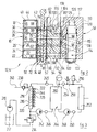
- FIG 1 10 is a rectangular seen in supervision Sheet called, which on its top and its Underside should be sprayed with working fluid.
- supervision Sheet For this purpose there is an upper spray head strip 12 and a lower one Spray head bar 14 is provided.
- the spray headers 12, 14 have the conveying plane of the Sheet metal 10 symmetrical structure, so that it is enough one the spray headers to describe in more detail below. As far as necessary to differentiate, the components the spray head strip 14 by a comma featured.
- the spray head strips 12, 14 each have a base part 16, which is an extruded multi-chamber profile, the Details are shown in Figure 2.
- Two side walls 18, 20 are through transverse walls 22, 24, 26, 28, 30 connected together.
- a bottom return channel 32 one, is obtained in this way overlying lubricant channel 34, one more time overflow channel 36 and one more compressed air duct 38 lying above transversal wall 30 extended upper end portions the side walls 18, 20 are mounting flanges 40, 42 radial integrally molded on the inside.
- On the latter is a cover part 44 put on, which also by cutting an extruded continuous material can. This limits the cover part 44 together with the transverse wall 30 a cable duct 46.
- Valve block On the side wall 18 is a total designated 48 Valve block with the interposition of a suitable opening for the different channels Flat seal 50 placed, for. B. screwed on.
- a suitable opening for the different channels Flat seal 50 placed, for. B. screwed on.
- Whose side remote from the base part 16 carries another Flat gasket 52 having channel openings can be detached (e.g. using a quick release) an adapter part 54.
- Its end face on the right carries with interposition a flat gasket with channel openings 56 a spray head designated 58 in total.
- the side wall 20 is assigned to a spray head Areas each with a return channel 32 in Connected return opening 60, one with the Lubricant channel 34 communicating lubricant opening 62, one with the flow channel 36 in connection standing flow opening 64, one with the compressed air channel 38 related compressed air opening 66 and with one connected to the cable duct 46 Provide cable opening 68.
- the valve block 48 includes a housing 70 which one with the return opening 60 aligned return channel 72, a lubricant channel aligned with the lubricant opening 62 74, one aligned with the flow opening 74 Flow channel 76 and one with the compressed air opening 66 in Connected compressed air channel 78 has.
- the different channels 72 to 78 are common Valve chamber 80 interrupted, in which a plate-shaped Valve slide 82 arranged in a fluid-tight manner is. This has control openings 84, 86, 88, 90, the Patterns of the arrangement of channels 72 to 78 corresponds.
- the valve spool 82 is between one in the drawing reproduced open position, in which the control openings 84 to 90 with the assigned one of the channels 72 to 78 aligned, and a pulled-out closed position, in which continuous sections of the valve spool 82 interrupt the channels 72 to 78, relocatable.
- the adapter part 54 has a housing 92, in which with a return channel 94 aligned with channels 72 to 78, a lubricant channel 96, a flow channel 98 and a Compressed air duct 100 are formed.
- the compressed air duct 100 has two vertically spaced Channel sections that in the peripheral wall or the bottom wall open a valve chamber 102.
- a valve plate 104 is provided by a tappet 106, which in turn is carried by an electromagnet 108 is moved.
- the spray head 58 has a housing 110 in which one stepped receiving bore 112 for an electromagnetic Injection nozzle 114 is provided.
- the injector 114 has the same structure as a fuel injector for gasoline engines.
- the receiving bore 112 in a small Distance surrounds and its ends with the flow channel 98 or the return duct 94 of the adapter part 54 via corresponding openings in the flat gasket 56 in Connection is established.
- shaped air nozzle channels 120 which are formed in a cap 122, which screwed onto the lower end of the injector 114 is.
- Air jets are used by the injectors 114 deform the dispensed liquid mist, e.g. too elliptical Press the cross-sectional shape wide.
- the lubricant is supplied to the injector 114 via an angled lubricant channel 124, which from Lubricant channel 96 of the adapter part 44 to an inlet section 126 of the injector 114 leads.
- a valve portion 128 of the injector 114 which comprises an electrical switching valve with which the lubricant flow to the injector with high frequency (typically around 3000 valve clearances / Minute, maximum 30,000 / minute) can be clocked.
- each spray head 58 each have a heating unit 130 and a temperature sensor 132 screwed on.
- a heating unit 130 and a temperature sensor 132 screwed on.
- these are as localized components shown in practice However, it can be an electrical resistance heating tape and act a temperature sensing wire that are wound on the housing 110 to the heat distributed feed and the temperature integrated over to measure the housing.
- the lubricant supply to the spray headers 12 and 14 takes place starting from a storage container 136, from which a lubricant pump 138 sucks.
- the pressure of the supplied lubricant is controlled by a Pressure control valve 140 set. This can e.g. one have magnets 142 acting in the closing direction, to be able to adjust the control pressure electrically.
- the Feed current for the electromagnet 142 is via a Cable 144 from a total of 146 designated control unit provided.
- cables are consistently through double lines indicated. It is understood that the cables 144 are not are comparable to data buses, rather for each signal to be transmitted contain a separate conductor. At the corresponding nodes of cables are more multi-conductor cables or a single conductor led out or admitted.
- a heat exchanger 148 Inside the reservoir 136 is a heat exchanger 148 arranged.
- a circulation pump 150 constantly a stream of water circulates through it a water heater 152 is heated. The latter is again via cable 144 from the control unit 146 powered.
- a surge tank 154 To compensate for temperature-related Volume changes of the heating water is on the water cycle a surge tank 154 connected.
- a lubricant circulation pump 156 To the Circulation of the lubricant in the reservoir 136 is provided.
- the temperature inside the reservoir 136 is determined a temperature sensor 158, the output signal of the cable 144 is transferred to the control unit 146.
- the compressed air duct 38 is supplied with compressed air by a compressor 160 and a controllable pressure control valve 162, the pressure setting magnet 164 again over the cable 144 is connected to the control unit 146.
- a heating water flow is circulated.
- a circulation pump 166 and one connected in series Water heater 168 is provided.
- An expansion tank 170 is again used to record temperature-related Changes in the total volume of water.
- Warm water released by the instantaneous water heater 168 is thus in the flow channel 36 of the base part 16th promoted and runs via the valve blocks 48 and Adapter parts 54 into the different spray heads 58, then reached via the adapter parts 54 and the valve blocks 48 the return channel 32 and from there of the circulation pump 166.
- the flow cross sections of the flow channel 36 and the Return channel 32 are large compared to the flow cross sections that in the valve blocks 48 and the adapter parts 54 trained channels, so that the different Spray heads all supplied with heating water evenly become.
- the lubricant channel 34 in the base part 16th between the flow channel 36 and the return channel 32 is arranged, the lubricant in the base part effective from both sides to the temperature of the Heating water heated.
- the middle Temperature is the base part 16 in its middle a temperature sensor 172, the output signal via a cable running in the cable duct 46 the control unit 146 is transmitted.
- a process computer belongs to the electrical control unit 146 180, the over not shown in detail Interface cards with a keypad 182, one Monitor 184 and a mass storage device 186 (e.g. hard disk) works together.
- the process computer works via appropriate interfaces 180 further with the temperature sensors 132, the temperature sensor 158, the temperature sensors 172 and 172 ', one cooperating with the sheet only indicated schematically Feed sensor 188 and various with the Sheet metal working position sensors together, only one of which is shown schematically at 190 is.
- the process computer 180 is suitable Interfaces and, if applicable, power levels with the pressure setting magnets 142 and 164, the instantaneous water heaters 152, 168, 168 ', the heating units 130 and the various Pumping the device connected, the connections to the various pumps and to the compressed air generator Blowers are not shown in detail.
- mass storage 186 are for different workpieces all data filed for spraying lubricant are needed. These are the ones in particular Areas of the workpiece surface that are sprayed at all the type of lubricant used and that in the different areas of the workpiece surface required quantities of lubricant.
- Organization computing circuit 192 can do the splitting on the three different setting options either depending on a given algorithm or depending on tables that are in mass storage 186 are stored.
- the organizational computing unit 192 can take into account that possibly in the longitudinal direction of the spray head bar 12, that is in the conveying direction of the sheets vertical direction, different lubricant deliveries be desired.
- Organizational computing circuit 192 therefore transmits to a temperature control circuit 194 a plurality of temperature setpoint signals, each one of the spray heads 58 are assigned.
- the temperature control circuit 194 is calculated from this a basic temperature control signal, which via a power level 196 for controlling the instantaneous water heater 168 serves. Accordingly, a second Power level 198 of the instantaneous water heater 152 with electricity provided. This is done in such a way that the temperature in the Storage container 136 below that to be expected in the control range minimum lubricant temperature.
- temperature control circuit 194 creates one Variety of temperature control signals for the individual Spray heads 58, which have power levels 200 on the Heating units 130 are given.
- Spray head 58 set in increasingly smaller control ranges is so that you can fine control the amount of lubricant dispensed only has small time constants there the amount of lubricant affected is increasingly smaller becomes.
- the organization control circuit 192 may be one Generate the temperature setpoint signal, which is the maximum amount of spray oil required in the next time. The reduction of this amount to the currently required The quantity then takes place via pulse width modulation the control signals for the electromagnets 108.
- the organizational computing circuit generates 192 a pressure setpoint signal, which on an input a control circuit 202 is given. The latter gives via a power stage 204 a feed signal to the Electromagnet 142 from.
- organization computer 192 issues a duty cycle command signal on an injection clock 205, which converts this signal into cyclical control pulses implements the electromagnets of the valve sections 128.
- a control circuit 206 is provided by the process computer 180 a compressed air setpoint signal which specifies the spray jet geometry to create a control signal for serves the electromagnet 164, again with the interposition a performance level 207.
- the compressed air setpoint signal can be from the process computer 180 depending on the path, i.e. based on the output signal of the Feed sensor 188 can be specified to the spray pattern to change depending on the route.
- the output signal of the injection clock 205 which the opening and closing times of the injectors 114 specifies is placed on an overlay circle 208 which the duty cycle with that on the workpiece too generating fog pattern, which is generated by the process computer 180 was retrieved from mass storage 186 and according to the feed of the sheet 10 line by line to the overlay circle 204 is passed on, AND-linked.
- the overlay circle 208 thus gives the various Injector 114 control signals through which the injection nozzles 114 are opened at predetermined times and be closed.
- Control channel for the spray head bar 14 has the same Structure and is not shown in Figure 1.
- the Lubricant amount in a wide range of approximately 1 to 8 is adjustable, of which a setting factor 6 via the temperature setting, a setting factor 2 about setting the pressure of the supplied lubricant he follows.
- Another setting option is in the duty cycle between the open and the closing time Injection nozzles 114.
- an adjustment range can be achieved in this way from about 1 to 10 or 1 to 100 depending on the period the spray head control signals (for a longer period can change the duty cycle in a wider range are covered as for a short period).
- Last fine adjustments of the dispensed lubricant quantities can be adjusted via a temperature adjustment the individual spray heads 58 by means of the heating units 130 done.
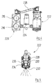
- Figures 3 to 5 show a second embodiment, in which a simpler device shown for spraying a sheet from only one side is.
- a lubricant pump 210 sucks from a reservoir 212 at. Your delivery side is via a pressure control valve 214 with an extruded oil channel part 216 (cf. also Figure 4) connected, which is thermally conductive with one made from the same profile material Compressed air duct part 218 is connected.
- the channel parts 216 and 218 together form a heat exchanger 220, which also forms a supporting part for spray heads 222.
- the latter are connected to the compressed air duct part via a solenoid valve 224 218 and via hose connections 226 connected to the oil passage part 216.
- the spray heads have 222 each have a housing formed with a stepped bore 228, in which an injection nozzle 230 sits.
- the injector 230 is on the discharge side of a nozzle cap Surround 232, which via a compressed air channel 234 a compressed air connection opening 236 communicates.
- the inside of the compressed air duct part 218 is over a Pressure control valve 238 with a compressed air line 240 connected.
- the oil passage part 216 is at one end with the outlet of the pressure control valve 214 connected.
- the exit of the Pressure control valve 214 is also at the inlet of a Circulation pump 242 connected to the inlet of the secondary circuit a heat exchanger 244 is connected.
- the Outlet of the secondary circuit of the heat exchanger 244 is via a temperature meter 245 with the second connection of the oil passage part 216.
- a flow meter 246 monitors the flow of lubricant through the heat exchanger 244.
- the primary circuit of the heat exchanger 244, which as Plate heat exchanger is designed with a Heating water circuit connected.
- the heating water outlet of the heat exchanger 244 is with connected to the inlet of a circulation pump 248, which via a flow meter 250 with the inlet of a water heater 252 is connected.
- a temperature sensor 254 is inserted in the connecting line between the outlet of the instantaneous water heater 252 and the heating water inlet of the heat exchanger 244.
- a temperature sensor 254 is inserted on this connecting line.
- this connecting line is also a vent 256, a pressure relief valve 258 and an expansion tank 260 connected.
- the temperature of the lubricant supplied to the oil passage part 216 can by appropriate electrical control of the instantaneous water heater 252 can be specified by one Rough adjustment of the lubricant emissions through the different To control injection nozzles 230.
- the amount of lubricant is the control pressure of the pressure control valve 214. This possibility can be seen in the Embodiment by manual adjustment make use of the pressure of the pressure regulating valve 214, but you can also control pressure electrically again adjust as described above. Finally can again the amount of lubricant dispensed via the Relationship between open time and closing time of the injection nozzles 230 can be determined. The shape of the Spray heads 222 emitted mist flows can be over determine the pressure control valve 238.
- Control unit for the in FIGS. 3 to 5 shown spray device work similar to that above Control described with reference to Figure 1.
Landscapes
- Physics & Mathematics (AREA)
- Thermal Sciences (AREA)
- Nozzles (AREA)
- Coating Apparatus (AREA)
Applications Claiming Priority (2)
| Application Number | Priority Date | Filing Date | Title |
|---|---|---|---|
| DE19916761 | 1999-04-14 | ||
| DE19916761A DE19916761A1 (de) | 1999-04-14 | 1999-04-14 | Verfahren und Vorrichtung zum Besprühen von Werkstücken |
Publications (2)
| Publication Number | Publication Date |
|---|---|
| EP1044724A2 true EP1044724A2 (fr) | 2000-10-18 |
| EP1044724A3 EP1044724A3 (fr) | 2003-06-04 |
Family
ID=7904480
Family Applications (1)
| Application Number | Title | Priority Date | Filing Date |
|---|---|---|---|
| EP00107244A Pending EP1044724A3 (fr) | 1999-04-14 | 2000-04-03 | Procédé et dispositif de pulvérisation sur des objets |
Country Status (3)
| Country | Link |
|---|---|
| US (1) | US6491756B1 (fr) |
| EP (1) | EP1044724A3 (fr) |
| DE (1) | DE19916761A1 (fr) |
Cited By (3)
| Publication number | Priority date | Publication date | Assignee | Title |
|---|---|---|---|---|
| CN103433308A (zh) * | 2013-07-24 | 2013-12-11 | 无锡圣恩铜业有限公司 | 铜杆冷却清洗装置 |
| EP3453466A1 (fr) * | 2017-09-08 | 2019-03-13 | SMS Group GmbH | Train de laminage destiné à laminer un produit métallique et procédé de fonctionnement d'un train de laminage |
| CN118755318A (zh) * | 2024-08-12 | 2024-10-11 | 日光媒(扬州)电气科技有限公司 | 一种纳米级光触媒涂料及其喷涂装置 |
Families Citing this family (11)
| Publication number | Priority date | Publication date | Assignee | Title |
|---|---|---|---|---|
| DE10239351B4 (de) * | 2002-08-28 | 2006-07-27 | Amtec Kistler Gmbh | Vorrichtung zum Auftragen eines Beschichtungsmittels |
| US7837131B2 (en) | 2003-03-27 | 2010-11-23 | Spraying Systems Co. | Modular automatic spray gun manifold |
| DE102004052005A1 (de) * | 2004-10-25 | 2006-05-11 | Raziol Zibulla & Sohn Gmbh | Vorrichtung und Verfahren zum Aufbringen eines flüssigen bis pastösen Mediums auf eine Werkstückoberfläche |
| DE102006017077B4 (de) * | 2006-04-10 | 2015-03-05 | Raziol Zibulla & Sohn Gmbh | Vorrichtung zum Aufbringen eines Befettungsmittels auf eine Werkstückoberfläche |
| US20080098783A1 (en) * | 2006-10-03 | 2008-05-01 | Ball Corporation | Non-Contact Spray Lubricator |
| MX2007015324A (es) * | 2006-12-18 | 2009-02-20 | Inventio Ag | Sistema y procedimiento para engrasar una instalacion de transporte. |
| ITFI20130134A1 (it) * | 2013-06-03 | 2014-12-04 | Eurosider Sas Di Milli Ottavio & C | Apparato di stabilizzazione termica secondo valori preimpostati dei dispositivi di atomizzazione per verniciatura. |
| US20150276299A1 (en) * | 2014-03-25 | 2015-10-01 | Lennox Industries Inc. | Fan operation management |
| DE102016011275B4 (de) | 2016-09-20 | 2023-06-15 | Raziol Zibulla & Sohn Gmbh | Vorrichtung, modulartiges System und Verfahren zum Aufbringen von flüssigem bis pastösem Befettungsmittel auf eine Werkstückoberfläche |
| CN110508429A (zh) * | 2019-09-04 | 2019-11-29 | 安徽居安新材料有限公司 | 一种装饰板材表面喷漆装置 |
| CN114178151B (zh) * | 2021-11-23 | 2022-11-22 | 东莞市金隆机械设备有限公司 | 灯罩双面喷涂方法 |
Citations (1)
| Publication number | Priority date | Publication date | Assignee | Title |
|---|---|---|---|---|
| DE19544016A1 (de) | 1995-11-27 | 1997-05-28 | Klaschka Gmbh & Co | Zerstäubungskopf für Flüssigkeiten sowie Einrichtung zum Besprühen von Werkstücken mit Flüssigkeiten mit solchen Zerstäubungsköpfen |
Family Cites Families (21)
| Publication number | Priority date | Publication date | Assignee | Title |
|---|---|---|---|---|
| US2976392A (en) * | 1953-09-04 | 1961-03-21 | Wabnitz Richard | Fluid distributing apparatus |
| US3756312A (en) * | 1970-12-28 | 1973-09-04 | American Hydrotherm Corp | Heat transfer system for a continuous lead extruder |
| US3833943A (en) * | 1972-07-10 | 1974-09-10 | P Sturtevant | Disposal system utilized with a heat source |
| US4170193A (en) * | 1976-04-16 | 1979-10-09 | Ball Corporation | Apparatus for applying lubricating materials to metallic substrates |
| US4132357A (en) * | 1976-06-23 | 1979-01-02 | Inmont Corporation | Apparatus and method for spray application of solvent-thinned coating compositions |
| US4131395A (en) * | 1976-09-29 | 1978-12-26 | Gusmer Corporation | Feeder for apparatus for ejecting a mixture of a plurality of liquids |
| US4187870A (en) * | 1977-05-06 | 1980-02-12 | Baker International Corporation | Valve actuator and pilot assembly therefor |
| US4247581A (en) * | 1977-10-14 | 1981-01-27 | Nordson Corporation | Method of coating with film-forming solids |
| US4505957A (en) * | 1979-07-19 | 1985-03-19 | Nordson Corporation | Coating by atomization of high (i.e., about 70-99% by weight) solids film-forming compositions |
| US4280806A (en) * | 1979-08-14 | 1981-07-28 | King Paul C | Prevaporizing oil burner and method |
| US4583582A (en) * | 1982-04-09 | 1986-04-22 | The Charles Stark Draper Laboratory, Inc. | Heat exchanger system |
| DE3423388A1 (de) * | 1984-06-25 | 1986-01-02 | Karrer System AG, Zollikon, Zürich | Verfahren und vorrichtung zum trocknen von fasermaterial |
| US5141156A (en) * | 1987-12-21 | 1992-08-25 | Union Carbide Chemicals & Plastics Technology Corporation | Methods and apparatus for obtaining a feathered spray when spraying liquids by airless techniques |
| DE4013064A1 (de) * | 1990-04-24 | 1991-10-31 | Ficht Gmbh | Verfahren zum spruehstrahlen von farbe und anordnung zur durchfuehrung des verfahrens |
| FR2662620A1 (fr) | 1990-05-31 | 1991-12-06 | Sames Sa | Installation de projection de produit de revetement pulverise a debit controle. |
| US5215253A (en) * | 1990-08-30 | 1993-06-01 | Nordson Corporation | Method and apparatus for forming and dispersing single and multiple phase coating material containing fluid diluent |
| DE9013885U1 (de) * | 1990-09-22 | 1990-12-06 | Grewenig, Otto, 5501 Welschbillig | Vorrichtung zum Erhitzen der einer Farbspritzpistole durch Schläuche o.dgl. zugeführten Farbe und Spritzluft |
| DE4217527C2 (de) * | 1991-06-01 | 1995-06-08 | Erno Raumfahrttechnik Gmbh | Vorrichtung zur Regelung eines Flüssigkeitsstromes |
| US5197800A (en) * | 1991-06-28 | 1993-03-30 | Nordson Corporation | Method for forming coating material formulations substantially comprised of a saturated resin rich phase |
| US5431315A (en) * | 1993-05-15 | 1995-07-11 | Massachusetts Institute Of Technology | Apparatus for applying uniform metal coatings |
| US5526981A (en) * | 1994-10-31 | 1996-06-18 | Sanson; Bruce A. | Adhesive spray system, and methods of constructing and utilizing same |
-
1999
- 1999-04-14 DE DE19916761A patent/DE19916761A1/de not_active Withdrawn
-
2000
- 2000-04-03 EP EP00107244A patent/EP1044724A3/fr active Pending
- 2000-04-13 US US09/548,856 patent/US6491756B1/en not_active Expired - Fee Related
Patent Citations (1)
| Publication number | Priority date | Publication date | Assignee | Title |
|---|---|---|---|---|
| DE19544016A1 (de) | 1995-11-27 | 1997-05-28 | Klaschka Gmbh & Co | Zerstäubungskopf für Flüssigkeiten sowie Einrichtung zum Besprühen von Werkstücken mit Flüssigkeiten mit solchen Zerstäubungsköpfen |
Cited By (3)
| Publication number | Priority date | Publication date | Assignee | Title |
|---|---|---|---|---|
| CN103433308A (zh) * | 2013-07-24 | 2013-12-11 | 无锡圣恩铜业有限公司 | 铜杆冷却清洗装置 |
| EP3453466A1 (fr) * | 2017-09-08 | 2019-03-13 | SMS Group GmbH | Train de laminage destiné à laminer un produit métallique et procédé de fonctionnement d'un train de laminage |
| CN118755318A (zh) * | 2024-08-12 | 2024-10-11 | 日光媒(扬州)电气科技有限公司 | 一种纳米级光触媒涂料及其喷涂装置 |
Also Published As
| Publication number | Publication date |
|---|---|
| EP1044724A3 (fr) | 2003-06-04 |
| US6491756B1 (en) | 2002-12-10 |
| DE19916761A1 (de) | 2000-11-02 |
Similar Documents
| Publication | Publication Date | Title |
|---|---|---|
| DE19740057C1 (de) | Kraftstoffversorgungssystem | |
| DE19916761A1 (de) | Verfahren und Vorrichtung zum Besprühen von Werkstücken | |
| DE2902955C2 (de) | Durchbiegungseinstellwalze | |
| EP0067928A2 (fr) | Système de chauffage pour véhicules moteurs résultant du laminage de l'huile de graissage | |
| DE69411127T2 (de) | Wiederaufladbarer Dampferzeuger | |
| DE2704551A1 (de) | Temperatursteuersystem | |
| DE10031852B4 (de) | Einrichtung zum Besprühen von Werkstücken | |
| DE1577867A1 (de) | Anlage zur Aufbringung von UEberzuegen,insbesondere zum Emaillieren von Draehten | |
| DE2719573A1 (de) | Verbrennung von leichtem oder extra leichtem heizoel zur waermeerzeugung in der groessenordnung von 6.000 bis 25.000 kcal/h | |
| DE10247778A1 (de) | Modular aufgebaute Farbdosiervorrichtung für eine Druckmaschine | |
| DE1874306U (de) | Vorrichtung zur erzeugung eines der schmierung dienenden oelnebels. | |
| DE69709350T2 (de) | Dampferzeuger | |
| DE4102580C2 (fr) | ||
| DE102018108800A1 (de) | Verfahren zum Betreiben eines hybriden Heizgerätes und hybrides Heizgerät | |
| EP4094843B1 (fr) | Ensemble tuyau et installation de traitement du gaz comprimé pour l'ensemble tuyau | |
| DE3138148C2 (de) | Verfahren und Vorrichtung zum Gießen von Zuckerwarenlösung | |
| AT394671B (de) | Einrichtung zum regulieren der balligkeit von walzwerks-walzen | |
| EP3812048A1 (fr) | Installation de traitement du gaz comprimé | |
| EP2837896A1 (fr) | Système d'humidification de l'air et procédé destiné à humidifier un flux d'air | |
| WO2000029115A1 (fr) | Dispositifs et procedes de temperage d'echantillons | |
| DE1577630A1 (de) | Fluessigkeitsserteileranlage | |
| DE4323196A1 (de) | Hochdruck-Spritzvorrichtung für Hartwachs | |
| DE3708712C1 (en) | Process and device for metering the components of multicomponent plastics, in particular polyurethane | |
| DE102008030061A1 (de) | Ventileinheit | |
| DE4212335C2 (de) | Extrusionsvorrichtung zur Herstellung von Platten |
Legal Events
| Date | Code | Title | Description |
|---|---|---|---|
| PUAI | Public reference made under article 153(3) epc to a published international application that has entered the european phase |
Free format text: ORIGINAL CODE: 0009012 |
|
| AK | Designated contracting states |
Kind code of ref document: A2 Designated state(s): AT BE CH CY DE DK ES FI FR GB GR IE IT LI LU MC NL PT SE |
|
| AX | Request for extension of the european patent |
Free format text: AL;LT;LV;MK;RO;SI |
|
| PUAL | Search report despatched |
Free format text: ORIGINAL CODE: 0009013 |
|
| STAA | Information on the status of an ep patent application or granted ep patent |
Free format text: STATUS: THE APPLICATION IS DEEMED TO BE WITHDRAWN |
|
| PUAF | Information related to the publication of a search report (a3 document) modified or deleted |
Free format text: ORIGINAL CODE: 0009199SEPU |
|
| 18D | Application deemed to be withdrawn |
Effective date: 20021031 |
|
| D18D | Application deemed to be withdrawn (deleted) | ||
| AK | Designated contracting states |
Designated state(s): AT BE CH CY DE DK ES FI FR GB GR IE IT LI LU MC NL PT SE |
|
| AX | Request for extension of the european patent |
Extension state: AL LT LV MK RO SI |
|
| R18D | Application deemed to be withdrawn (corrected) |
Effective date: 20021102 |
|
| D17D | Deferred search report published (deleted) |