EP1044725A2 - Dipositif de pulvérisation de liquides sur des objets - Google Patents
Dipositif de pulvérisation de liquides sur des objets Download PDFInfo
- Publication number
- EP1044725A2 EP1044725A2 EP00106489A EP00106489A EP1044725A2 EP 1044725 A2 EP1044725 A2 EP 1044725A2 EP 00106489 A EP00106489 A EP 00106489A EP 00106489 A EP00106489 A EP 00106489A EP 1044725 A2 EP1044725 A2 EP 1044725A2
- Authority
- EP
- European Patent Office
- Prior art keywords
- wall
- suction
- housing
- section
- cavity wall
- Prior art date
- Legal status (The legal status is an assumption and is not a legal conclusion. Google has not performed a legal analysis and makes no representation as to the accuracy of the status listed.)
- Withdrawn
Links
Images

Classifications
-
- B—PERFORMING OPERATIONS; TRANSPORTING
- B05—SPRAYING OR ATOMISING IN GENERAL; APPLYING FLUENT MATERIALS TO SURFACES, IN GENERAL
- B05B—SPRAYING APPARATUS; ATOMISING APPARATUS; NOZZLES
- B05B13/00—Machines or plants for applying liquids or other fluent materials to surfaces of objects or other work by spraying, not covered by groups B05B1/00 - B05B11/00
- B05B13/02—Means for supporting work; Arrangement or mounting of spray heads; Adaptation or arrangement of means for feeding work
- B05B13/0207—Means for supporting work; Arrangement or mounting of spray heads; Adaptation or arrangement of means for feeding work the work being an elongated body, e.g. wire or pipe
-
- B—PERFORMING OPERATIONS; TRANSPORTING
- B05—SPRAYING OR ATOMISING IN GENERAL; APPLYING FLUENT MATERIALS TO SURFACES, IN GENERAL
- B05B—SPRAYING APPARATUS; ATOMISING APPARATUS; NOZZLES
- B05B16/00—Spray booths
- B05B16/60—Ventilation arrangements specially adapted therefor
-
- B—PERFORMING OPERATIONS; TRANSPORTING
- B05—SPRAYING OR ATOMISING IN GENERAL; APPLYING FLUENT MATERIALS TO SURFACES, IN GENERAL
- B05B—SPRAYING APPARATUS; ATOMISING APPARATUS; NOZZLES
- B05B16/00—Spray booths
- B05B16/90—Spray booths comprising conveying means for moving objects or other work to be sprayed in and out of the booth, e.g. through the booth
- B05B16/95—Spray booths comprising conveying means for moving objects or other work to be sprayed in and out of the booth, e.g. through the booth the objects or other work to be sprayed lying on, or being held above the conveying means, i.e. not hanging from the conveying means
-
- B—PERFORMING OPERATIONS; TRANSPORTING
- B21—MECHANICAL METAL-WORKING WITHOUT ESSENTIALLY REMOVING MATERIAL; PUNCHING METAL
- B21B—ROLLING OF METAL
- B21B45/00—Devices for surface or other treatment of work, specially combined with or arranged in, or specially adapted for use in connection with, metal-rolling mills
- B21B45/02—Devices for surface or other treatment of work, specially combined with or arranged in, or specially adapted for use in connection with, metal-rolling mills for lubricating, cooling, or cleaning
- B21B45/0239—Lubricating
- B21B45/0245—Lubricating devices
- B21B45/0248—Lubricating devices using liquid lubricants, e.g. for sections, for tubes
- B21B45/0251—Lubricating devices using liquid lubricants, e.g. for sections, for tubes for strips, sheets, or plates
Definitions
- the invention relates to a device for spraying of flat workpieces, especially sheet metal, with a Liquid, e.g. a lubricant according to the preamble of claim 1.
- Such devices are particularly in connection with press lines used to press or to spray deep-drawn sheets with a lubricant. This will cause cracking and drawing marks in the workpiece avoided and will reduce the deformation necessary force and protection of the pressing tools reached.
- Such a device is known from EP 0 060 375 A2 known.
- the suction device becomes relatively smaller Suction power operated, so that spray fans emerge from the spray heads due to air movements not be disturbed. This reduces the effectiveness the suction device when setting Flow conditions within the housing of the spray device.
- suction device within such The device is known from EP 0 060 375 A2.
- suction device with relatively low suction power operated to allow spray fans out of the spray heads emerge, are not disturbed by air movements. This reduces the effectiveness of the suction device the setting of defined flow conditions within the housing of the spray device and thus its efficiency when extracting fog.
- the present invention is therefore intended to provide a device further developed for spraying flat workpieces be that on the passage windows of the housing certainly no liquid mist escapes.
- a device as reproduced in claim 2 sucks both above the conveying level of the workpieces escaping liquid mist as well as below the Conveying mist emerging from the workpiece conveyor level in the area the passage openings of the housing. This is particularly so then an advantage if the workpiece is both Sides is sprayed here.
- the width of the suction slot in the longitudinal direction of the slot to vary so in different places of the suction slit either despite the unequal geometry of the vacuum pathways still a constant To ensure suction power, or suction power in To vary the longitudinal direction of the suction slot, e.g. in Edge areas to suck or increased suction power in such slot areas, which are reduced by internal Installation of the housing better against liquid mist are shadowed.
- a liquid separator as specified in claim 9 is particularly well suited for effective separation of oil droplets.
- the development of the invention according to claim 13 allows an adjustment of the suction shafts fixed to the housing Workpiece conveying direction in parallel direction.
- a seal of the interior of the housing is obtained against direct exposure to liquid mist from the entry-side passage window of the housing to the exit-side passage window.
- the training according to claim 17 is in view a good edge seal between the shielding plate and Housing is an advantage.
- FIG. 10 denotes a housing as a whole, in which sheet metal pieces 12 from above and below with a Lubricant mist cone 14 or 14 'brought into contact become.
- the housing has a top wall 16, an inlet side Transverse wall 18, an outlet-side transverse wall 20, parallel to the direction of conveyance of the sheets (indicated by arrow 22) extending side walls 24 and a bottom wall 26, which at the same time as a collecting tub for not from the sheet metal pieces 12 entrained litter oil is used.
- Transport rollers are located in the side walls 24 of the housing 10 28 stored, which is a horizontal funding level for specify the sheet metal pieces 12.
- the transport rollers 28 are driven by a common toothed belt 30 which the output gear 32 of a not shown Drive motor works.
- the entry-side transverse wall 18 consists of two pivotable Doors 34, 36, which are mirror images of through the transport rollers 28 arranged conveyor plane are.
- the exit-side transverse wall 20 is a mirror image of the Cross wall 18 constructed from two doors 38, 40.
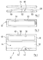
- the door 34 (see FIG. 4) has an outer wall 42 and one inner wall 44 spaced therefrom from the interior of the housing upper ends of outer wall 42 and inner wall 44 are connected by an edge wall 46.
- edge wall 46 To the front or ends of the door 38 to be thought behind the plane of the drawing, 40 is that through outer wall 42, inner wall 44 and edge wall 46 channel formed by end walls 48 in the longitudinal direction of the channel locked.
- the inner wall 44 an upper wall portion spaced more from the outer wall 50 and just a little bit from the outer wall 42 spaced lower wall section 52.
- the lower ends of outer wall 42 and wall section 52 define one Suction slot 54.
- the wall sections 50 and 52 are through an oblique central wall section 56 connected, such that the transverse cross section of the door 34 one Rectangle with a right-angled triangle and corresponds to the beak carried by the latter.
- connection opening 58 In the wall section 50 there is a close to its edges extending connection opening 58 is provided.
- the door 34 is over at its upper outer end a hinge 60 is pivotally attached to the housing 10.
- the closed position of the doors is shown in FIG.
- Each of the doors can hinge around the associated one be pivoted away from the housing to access the Preserve the interior of the housing.
- Suction shafts are provided, and the suction shafts are over Lines 70, 72 with the input of an electrostatic filter 74 connected. Its output is one with the input Suction blower 76 connected.
- a hollow profile 78 is provided inside the housing 10 , which limited a compressed air channel 80.
- the hollow profile 78 carries via solenoid valves 82 spray heads 84, which under regular Distance along the hollow profile 78 are distributed.
- a second hollow profile 86 is thermally conductive with its underside placed on the top of the hollow profile 78. It delimits a lubricant channel 88.
- the latter is connected by hoses 90 to injectors 72 which correspond to injection nozzles used in diesel engines and serve the that supplied via the lubricant channel 88 Atomize lubricant finely.
- the one from the compressed air duct 80 via the solenoid valves 82 to the spray heads Air supplied serves to support the nebulization and the mist cone generated by the injectors 92 14 to shape, in particular to flatten.
- the injection nozzles 92 extend with their end section through matching openings in a section 96 an angled shield 98.
- the section 96 of the shield plate 98 is inclined so much that larger drops of lubricant that grow together of fog droplets on the shielding plate, below Drain gravity down along the sheet.
- An inclination ensuring such a flow a sheet is used in the present description and referred to in the claims as the run-off angle. At the The exemplary embodiment considered here is the run-off angle about 20 °.
- the section 96 of the shield plate 98 extends until against the wall section 56 and settles in one bevelled end section 100, which is parallel to the wall section 56 of the door 38 runs.
- the shield plate has immediately upstream of section 96 98 a further under opposite discharge angle arranged section 102, which extends up to the wall section 56 extends the door 34 and there again has small end portion 104, the positive abuts the wall section 56.
- the geometry shown in the drawing shows the axis of the spray heads 84 perpendicular to the section 96 of the shield plate 98 and thus closes with the conveyor level the sheets 12 form an angle of approximately 70 °, so that the fog cone 14 with one of the conveying direction 22 opposite speed component on a underlying sheet metal 12 strikes.
- a floor pan 130 is provided in the electrostatic filter 74, which collects the lubricant deposited there.
- the lowest point of the bottom wall 130 is via a drain line 132 with the through the bottom wall 26 of the housing 10 lubricant sump formed. The Do not dispose of lubricant that has been taken from the metal sheets can be done at a central point namely when the bottom wall 26 runs out.
- a piece of sheet metal to be sprayed reaches one by one predetermined distance arranged in front of the fog cones 14
- Position transmitter 134 the spray heads 84 are activated and create the fog cones 14. Moving forward of the sheet metal piece 12 on the transport rollers 28 then both sides of the sheet metal piece 12 with lubricant mist busy. Reaches the rear end of the piece of sheet metal 12 one behind the by a predetermined distance Fog cone 14 arranged position transmitter 136, the Mist generation by the spray heads 84 ended.
- the suction power of the suction fan is preferably 76 approximately ten times the volume of the spray heads 84 fed Air volume. This ensures that no air containing lubricant mist from the Housing 10 emerges.
- a lower limit for suction power of the suction fan 76 is at five times the Seen the volume of air supplied, an increase in Suction power of the suction fan 76 over twenty times of the volume of compressed air supplied would be unnecessary air suck from the area around the housing.
- the doors 34 to 40 can be moved around their Hinges 60 to be given away.
- the upper doors 38 and 40 can and in the open position by lever 138 can be locked, which is pivoted through these doors and with housing-fixed mounting bolts (not shown) work together.
- the bottom wall 26 also collects oil to be sprayed Pieces of sheet metal 12 with different edge contours by gaps between such sheet metal pieces 12 flows through.
- connection openings 64 and 58 do not cover the whole Cross section of the suction shaft 62 or the one facing it Wall section 50 of the inner wall 44 of the hollow-walled door 34. Facing each other with the door 34 closed frontal connecting walls that the wall section 50 and the suction shaft 62 in this embodiment complete, there is a round connection opening executed near one of the end walls 48.
- the Diameter of these two aligned connection openings is about the size of the narrow side of the rectangular connection opening 64 of the related with Figures 3 and 4 embodiment described.
Landscapes
- Details Or Accessories Of Spraying Plant Or Apparatus (AREA)
Applications Claiming Priority (2)
| Application Number | Priority Date | Filing Date | Title |
|---|---|---|---|
| DE19916762 | 1999-04-14 | ||
| DE19916762A DE19916762A1 (de) | 1999-04-14 | 1999-04-14 | Vorrichtung zum Besprühen von Werkstücken mit einer Flüssigkeit |
Publications (1)
| Publication Number | Publication Date |
|---|---|
| EP1044725A2 true EP1044725A2 (fr) | 2000-10-18 |
Family
ID=7904481
Family Applications (1)
| Application Number | Title | Priority Date | Filing Date |
|---|---|---|---|
| EP00106489A Withdrawn EP1044725A2 (fr) | 1999-04-14 | 2000-03-25 | Dipositif de pulvérisation de liquides sur des objets |
Country Status (2)
| Country | Link |
|---|---|
| EP (1) | EP1044725A2 (fr) |
| DE (1) | DE19916762A1 (fr) |
Cited By (2)
| Publication number | Priority date | Publication date | Assignee | Title |
|---|---|---|---|---|
| WO2002055215A3 (fr) * | 2001-01-12 | 2002-09-19 | Josef Schiele Ohg | Dispositif d'enduction pour une piece a usiner allongee |
| EP2006029A3 (fr) * | 2007-06-19 | 2012-06-20 | Amtec Kistler GmbH | Dispositif d'application d'un produit d'application sur un substrat |
Families Citing this family (4)
| Publication number | Priority date | Publication date | Assignee | Title |
|---|---|---|---|---|
| DE10159443B4 (de) * | 2001-12-04 | 2006-05-04 | Zimmer Ag | Vorrichtung zum Wechseln von Düsen |
| DE102005062527A1 (de) * | 2005-12-16 | 2007-06-21 | Gebr. Schmid Gmbh & Co. | Vorrichtung und Verfahren zur Oberflächenbehandlung von Substraten |
| DE102013006331A1 (de) * | 2013-04-12 | 2014-10-16 | Technotrans Ag | Werkstückbeöler und Verfahren zum Beölen von Werkstücken |
| DE102014213401A1 (de) | 2014-03-28 | 2015-10-01 | Sms Group Gmbh | Vorrichtung zum Aufbringen und Absaugen von Betriebsstoffen im Einlauf von Kaltwalzanlagen |
Citations (1)
| Publication number | Priority date | Publication date | Assignee | Title |
|---|---|---|---|---|
| EP0060375A2 (fr) | 1981-03-13 | 1982-09-22 | VOEST-ALPINE Aktiengesellschaft | Dispositif pour lubrifier des tôles en forme de ruban ou plaque |
Family Cites Families (5)
| Publication number | Priority date | Publication date | Assignee | Title |
|---|---|---|---|---|
| US2400315A (en) * | 1944-06-10 | 1946-05-14 | Jens A Paasche | Coating machine |
| DE1796280A1 (de) * | 1967-07-24 | 1972-11-09 | Mcmillan Bloedel Ltd | Verfahren und Vorrichtung zum Verspruehen von Fluessigkeiten |
| US3475202A (en) * | 1967-10-19 | 1969-10-28 | Hendrik F Bok | Method for controlling a spray-coating environment |
| FR2551365B1 (fr) * | 1983-08-01 | 1986-03-28 | Lorraine Laminage | Dispositif pour huiler des toles en bande continue |
| DE4316672C1 (de) * | 1993-05-13 | 1994-07-28 | Mannesmann Ag | Einrichtung zur Herstellung von metallischen Körpern durch Aufsprühen |
-
1999
- 1999-04-14 DE DE19916762A patent/DE19916762A1/de not_active Withdrawn
-
2000
- 2000-03-25 EP EP00106489A patent/EP1044725A2/fr not_active Withdrawn
Patent Citations (1)
| Publication number | Priority date | Publication date | Assignee | Title |
|---|---|---|---|---|
| EP0060375A2 (fr) | 1981-03-13 | 1982-09-22 | VOEST-ALPINE Aktiengesellschaft | Dispositif pour lubrifier des tôles en forme de ruban ou plaque |
Cited By (2)
| Publication number | Priority date | Publication date | Assignee | Title |
|---|---|---|---|---|
| WO2002055215A3 (fr) * | 2001-01-12 | 2002-09-19 | Josef Schiele Ohg | Dispositif d'enduction pour une piece a usiner allongee |
| EP2006029A3 (fr) * | 2007-06-19 | 2012-06-20 | Amtec Kistler GmbH | Dispositif d'application d'un produit d'application sur un substrat |
Also Published As
| Publication number | Publication date |
|---|---|
| DE19916762A1 (de) | 2000-11-02 |
Similar Documents
| Publication | Publication Date | Title |
|---|---|---|
| EP0765696A1 (fr) | Dispositif pour maintenir à sec un feuillard laminé à froid à la sortie d'installations de laminage à froid de bandes | |
| EP1979103B1 (fr) | Dispositif de nettoyage de bande | |
| EP0780332B1 (fr) | Dispositif pour agir sur des feuilles dans un appareil de sortie de feuilles | |
| DE19705006C2 (de) | Vorrichtung zum Zuführen und Absaugen von Farbe in Druckmaschinen | |
| EP0533054A2 (fr) | Dispositif pour la purification d'un bain pour liquides | |
| DE3640699C2 (fr) | ||
| DE2743530C3 (de) | Vorrichtung zum Reinigen von großflächigen TextUauflagen, insbesondere von Teppichen und Teppichboden | |
| EP0629425A1 (fr) | Dispositif filtrant à bande pour la purification des liquides d'usinage | |
| EP1466670B1 (fr) | Dispositif de nettoyage de cabine de revêtement par poudrage et cabine de revêtement par poudrage munie d'un dispositif de nettoyage | |
| DE102021118686A1 (de) | Bodenfräsmaschine und verfahren zum absaugen und ausblasen staubbelasteter luft bei einer bodenfräsmaschine | |
| DE69502442T2 (de) | Verfahren und Vorrichtung zur Sprühbeschichtung | |
| DE102010007479B3 (de) | Anlage zum Beschichten von Gegenständen | |
| DE19916762A1 (de) | Vorrichtung zum Besprühen von Werkstücken mit einer Flüssigkeit | |
| DE3427766A1 (de) | Vorrichtung zum einfetten von blechbaendern | |
| AT393237B (de) | Duese fuer das trocknen von glastafeln | |
| DE2116042A1 (de) | Verfahren und Vorrichtung zur Entfernung von Pulver aus der Atmosphäre | |
| DE19822537A1 (de) | Reinigungsvorrichtung für Karosserien von Fahrzeugen | |
| EP2072146A2 (fr) | Enceinte de revêtement modulaire | |
| EP0391091B1 (fr) | Filtre à bande avec aspiration | |
| DE69020165T2 (de) | Egalisieranordnung für lötstoff. | |
| DE19521267C2 (de) | Ölnebelentferner für das Ölkontrollsystem einer Presse | |
| EP0939592B1 (fr) | Dispositif de mise en forme de pate | |
| DE29814293U1 (de) | Entstaubungsanlage | |
| DE10236264A1 (de) | Bepuderungseinheit, Bepuderungsstation und Verfahren zum Betreiben von solchen | |
| DE629418C (de) | Abstaubvorrichtung |
Legal Events
| Date | Code | Title | Description |
|---|---|---|---|
| PUAI | Public reference made under article 153(3) epc to a published international application that has entered the european phase |
Free format text: ORIGINAL CODE: 0009012 |
|
| AK | Designated contracting states |
Kind code of ref document: A2 Designated state(s): AT BE CH CY DE DK ES FI FR GB GR IE IT LI LU MC NL PT SE |
|
| AX | Request for extension of the european patent |
Free format text: AL;LT;LV;MK;RO;SI |
|
| STAA | Information on the status of an ep patent application or granted ep patent |
Free format text: STATUS: THE APPLICATION IS DEEMED TO BE WITHDRAWN |
|
| 18D | Application deemed to be withdrawn |
Effective date: 20021001 |