EP1044794A2 - Polsterumwandlungsmaschine und Verfahren zu deren Verwendung mit mehreren Eingangsrollenführungen - Google Patents
Polsterumwandlungsmaschine und Verfahren zu deren Verwendung mit mehreren Eingangsrollenführungen Download PDFInfo
- Publication number
- EP1044794A2 EP1044794A2 EP99309946A EP99309946A EP1044794A2 EP 1044794 A2 EP1044794 A2 EP 1044794A2 EP 99309946 A EP99309946 A EP 99309946A EP 99309946 A EP99309946 A EP 99309946A EP 1044794 A2 EP1044794 A2 EP 1044794A2
- Authority
- EP
- European Patent Office
- Prior art keywords
- cushioning
- stock material
- strip
- conversion
- moving blade
- Prior art date
- Legal status (The legal status is an assumption and is not a legal conclusion. Google has not performed a legal analysis and makes no representation as to the accuracy of the status listed.)
- Withdrawn
Links
Images

Classifications
-
- B—PERFORMING OPERATIONS; TRANSPORTING
- B31—MAKING ARTICLES OF PAPER, CARDBOARD OR MATERIAL WORKED IN A MANNER ANALOGOUS TO PAPER; WORKING PAPER, CARDBOARD OR MATERIAL WORKED IN A MANNER ANALOGOUS TO PAPER
- B31D—MAKING ARTICLES OF PAPER, CARDBOARD OR MATERIAL WORKED IN A MANNER ANALOGOUS TO PAPER, NOT PROVIDED FOR IN SUBCLASSES B31B OR B31C
- B31D5/00—Multiple-step processes for making three-dimensional [3D] articles
- B31D5/0039—Multiple-step processes for making three-dimensional [3D] articles for making dunnage or cushion pads
- B31D5/0043—Multiple-step processes for making three-dimensional [3D] articles for making dunnage or cushion pads including crumpling flat material
- B31D5/0047—Multiple-step processes for making three-dimensional [3D] articles for making dunnage or cushion pads including crumpling flat material involving toothed wheels
-
- B—PERFORMING OPERATIONS; TRANSPORTING
- B65—CONVEYING; PACKING; STORING; HANDLING THIN OR FILAMENTARY MATERIAL
- B65H—HANDLING THIN OR FILAMENTARY MATERIAL, e.g. SHEETS, WEBS, CABLES
- B65H23/00—Registering, tensioning, smoothing or guiding webs
- B65H23/04—Registering, tensioning, smoothing or guiding webs longitudinally
- B65H23/048—Registering, tensioning, smoothing or guiding webs longitudinally by positively actuated movable bars or rollers
-
- B—PERFORMING OPERATIONS; TRANSPORTING
- B31—MAKING ARTICLES OF PAPER, CARDBOARD OR MATERIAL WORKED IN A MANNER ANALOGOUS TO PAPER; WORKING PAPER, CARDBOARD OR MATERIAL WORKED IN A MANNER ANALOGOUS TO PAPER
- B31D—MAKING ARTICLES OF PAPER, CARDBOARD OR MATERIAL WORKED IN A MANNER ANALOGOUS TO PAPER, NOT PROVIDED FOR IN SUBCLASSES B31B OR B31C
- B31D2205/00—Multiple-step processes for making three-dimensional articles
- B31D2205/0005—Multiple-step processes for making three-dimensional articles for making dunnage or cushion pads
- B31D2205/0011—Multiple-step processes for making three-dimensional articles for making dunnage or cushion pads including particular additional operations
- B31D2205/0017—Providing stock material in a particular form
- B31D2205/0023—Providing stock material in a particular form as web from a roll
-
- B—PERFORMING OPERATIONS; TRANSPORTING
- B31—MAKING ARTICLES OF PAPER, CARDBOARD OR MATERIAL WORKED IN A MANNER ANALOGOUS TO PAPER; WORKING PAPER, CARDBOARD OR MATERIAL WORKED IN A MANNER ANALOGOUS TO PAPER
- B31D—MAKING ARTICLES OF PAPER, CARDBOARD OR MATERIAL WORKED IN A MANNER ANALOGOUS TO PAPER, NOT PROVIDED FOR IN SUBCLASSES B31B OR B31C
- B31D2205/00—Multiple-step processes for making three-dimensional articles
- B31D2205/0005—Multiple-step processes for making three-dimensional articles for making dunnage or cushion pads
- B31D2205/0011—Multiple-step processes for making three-dimensional articles for making dunnage or cushion pads including particular additional operations
- B31D2205/0047—Feeding, guiding or shaping the material
-
- B—PERFORMING OPERATIONS; TRANSPORTING
- B31—MAKING ARTICLES OF PAPER, CARDBOARD OR MATERIAL WORKED IN A MANNER ANALOGOUS TO PAPER; WORKING PAPER, CARDBOARD OR MATERIAL WORKED IN A MANNER ANALOGOUS TO PAPER
- B31D—MAKING ARTICLES OF PAPER, CARDBOARD OR MATERIAL WORKED IN A MANNER ANALOGOUS TO PAPER, NOT PROVIDED FOR IN SUBCLASSES B31B OR B31C
- B31D2205/00—Multiple-step processes for making three-dimensional articles
- B31D2205/0005—Multiple-step processes for making three-dimensional articles for making dunnage or cushion pads
- B31D2205/0011—Multiple-step processes for making three-dimensional articles for making dunnage or cushion pads including particular additional operations
- B31D2205/0058—Cutting; Individualising the final products
-
- B—PERFORMING OPERATIONS; TRANSPORTING
- B31—MAKING ARTICLES OF PAPER, CARDBOARD OR MATERIAL WORKED IN A MANNER ANALOGOUS TO PAPER; WORKING PAPER, CARDBOARD OR MATERIAL WORKED IN A MANNER ANALOGOUS TO PAPER
- B31D—MAKING ARTICLES OF PAPER, CARDBOARD OR MATERIAL WORKED IN A MANNER ANALOGOUS TO PAPER, NOT PROVIDED FOR IN SUBCLASSES B31B OR B31C
- B31D2205/00—Multiple-step processes for making three-dimensional articles
- B31D2205/0005—Multiple-step processes for making three-dimensional articles for making dunnage or cushion pads
- B31D2205/0011—Multiple-step processes for making three-dimensional articles for making dunnage or cushion pads including particular additional operations
- B31D2205/0064—Stabilizing the shape of the final product, e.g. by mechanical interlocking
-
- B—PERFORMING OPERATIONS; TRANSPORTING
- B31—MAKING ARTICLES OF PAPER, CARDBOARD OR MATERIAL WORKED IN A MANNER ANALOGOUS TO PAPER; WORKING PAPER, CARDBOARD OR MATERIAL WORKED IN A MANNER ANALOGOUS TO PAPER
- B31D—MAKING ARTICLES OF PAPER, CARDBOARD OR MATERIAL WORKED IN A MANNER ANALOGOUS TO PAPER, NOT PROVIDED FOR IN SUBCLASSES B31B OR B31C
- B31D2205/00—Multiple-step processes for making three-dimensional articles
- B31D2205/0005—Multiple-step processes for making three-dimensional articles for making dunnage or cushion pads
- B31D2205/0076—Multiple-step processes for making three-dimensional articles for making dunnage or cushion pads involving particular machinery details
- B31D2205/0082—General layout of the machinery or relative arrangement of its subunits
-
- B—PERFORMING OPERATIONS; TRANSPORTING
- B65—CONVEYING; PACKING; STORING; HANDLING THIN OR FILAMENTARY MATERIAL
- B65H—HANDLING THIN OR FILAMENTARY MATERIAL, e.g. SHEETS, WEBS, CABLES
- B65H2801/00—Application field
- B65H2801/63—Dunnage conversion
-
- Y—GENERAL TAGGING OF NEW TECHNOLOGICAL DEVELOPMENTS; GENERAL TAGGING OF CROSS-SECTIONAL TECHNOLOGIES SPANNING OVER SEVERAL SECTIONS OF THE IPC; TECHNICAL SUBJECTS COVERED BY FORMER USPC CROSS-REFERENCE ART COLLECTIONS [XRACs] AND DIGESTS
- Y10—TECHNICAL SUBJECTS COVERED BY FORMER USPC
- Y10S—TECHNICAL SUBJECTS COVERED BY FORMER USPC CROSS-REFERENCE ART COLLECTIONS [XRACs] AND DIGESTS
- Y10S493/00—Manufacturing container or tube from paper; or other manufacturing from a sheet or web
- Y10S493/967—Dunnage, wadding, stuffing, or filling excelsior
Definitions
- the invention herein described relates generally to cushioning conversion machines and more particularly to improvements in controlling the tension of the stock material fed into such machines for conversion into a dunnage product and in controlling the dunnage product during a cutting operation to minimize machine jams.
- protective packaging material is often placed in the shipping container to fill any voids and/or to cushion the item during the shipping process.
- Some commonly used protective packaging materials are plastic foam peanuts and plastic bubble pack. While these conventional plastic materials seem to perform adequately as cushioning products, they are not without disadvantages. Perhaps the most serious drawback of plastic bubble wrap and plastic foam peanuts is their affect on our environment. Quite simply, these plastic packaging materials are not biodegradable, and therefore they cannot avoid further multiplying our planet's already critical waste disposal problems. The non-biodegradability of these packaging materials has become increasingly important in light of many industries adopting more progressive policies in terms of environmental responsibility.
- Paper protective packaging material a popular alternative. Paper is biodegradable, recyclable and composed of a renewable resource, making it an environmentally responsible choice for conscientious shippers.
- This conversion may be accomplished by a cushioning conversion machine, such as that disclosed in commonly assigned U.S. Patent No. 5,123,889.
- the conversion machine disclosed in U. S. Patent 5,123,889 converts sheet stock material, such as paper in multi-ply form, into relatively low density pads. Specifically, the machine converts this stock material into a continuous unconnected strip having lateral pillow portions separated by a thin central band. This strip is connected as by coining along its central band to form a coined strip which is cut into sections, or pads, of a desired length.
- the stock material preferably consists of three superimposed webs or layers of biodegradable, recyclable and reusable thirty-pound Kraft paper rolled onto a hollow cylindrical tube.
- a thirty-inch wide roll of this paper which is approximately 450 feet long, weighs about 35 pounds and will provide cushioning equal to approximately sixty cubic feet of plastic foam peanuts while at the same time requiring less than onethirtieth the storage space.
- the conversion machines known in the prior art including the one shown in U.S. Patent 5,123,889, have used a freely rotating roll from which the stock material to be converted is fed by means of the same mechanism that advances the material through the forming portion of the machine. Specifically a pair of gears that have performed a connecting operation have been used to advance the material being converted. These gears stop and start their rotation during the conversion process, and this results in the need to accelerate the stock roll every time the gears start, with resulting changes in the tension of material being fed through the conversion machine. These changes in the tension of the material can affect the quality of the dunnage product being produced.
- the rotational inertia of the stock roll can cause the stock roll to overrun and form a loose loop of material at the supply end of the conversion machine.
- the material will be at a relatively low tension until the loose loop of material is taken up, at which point the tension on the paper will rapidly increase, almost instantaneously, to a relatively high level until the stock roll accelerates to match the feed rate through the machine. This quick change in tension can cause the material to tear, as well as degrade the quality of the dunnage product being produced.
- a commonly used severing assembly includes a moving blade which travels between a retracted rest position and an extended full cut position. More specifically, a cutting cycle of the blade includes a cutting stroke during which the formed strip of dunnage is cut and a return stroke during which the blade returns to the rest position. During the cutting stroke, the moving blade unit travels across the dunnage outlet opening and cuts the dunnage strip into a cut section, or pad, of a desired length.
- the present invention provides improvements in a cushioning conversion machine and method for converting sheet stock material into a cushioning dunnage product. These improvements enable better control over the tension of the stock material fed into such machines for conversion into a dunnage product and better control over the dunnage product during a cutting operation to minimize the chance of a machine jam.
- a cushioning conversion machine and method for converting multi-ply sheet stock material into a cushioning dunnage product are characterized by a stock supply assembly which supplies stock material to be converted, and a conversion assembly which draws the stock material from the stock supply and converts the stock material into a strip of cushioning.
- the stock supply assembly includes a plurality of constant entry guides at an upstream end of the machine for passage of respective plies of stock material thereover.
- the stock supply assembly includes a biased damper over which the multi-ply stock material can be trained before passage to constant entry guides, and a plurality of separators between the constant entry guides and the conversion assembly.
- a cushioning conversion machine and method for converting sheet stock material into a cushioning dunnage product are characterized by a stock supply assembly which supplies stock material to be converted, a conversion assembly which draws the stock material from the stock supply and converts the stock material into a strip of cushioning, and a severing assembly for severing the strip of cushioning to form a pad.
- the severing assembly includes a moving blade mounted for movement across a strip path between a retracted position and an extended position for cutting the strip, and a shutter movable with the moving blade for substantially blocking the strip path when the moving blade is in its extended position.
- the shutter has an upstream surface flush with an upstream surface of the moving blade, and the shutter and moving blade are both mounted to a blade holder that is mounted for swinging movement relative to another blade that coacts with the moving blade to cut the strip.
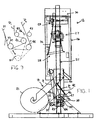
- the conversion machine 12 has a stock supply which, in the illustrated embodiment, includes an integral stock roll holder assembly 19 for supporting a roll 21 of sheet stock material 22.
- the sheet material 20 may be supplied from a separate stand holding the sheet material, or by other suitable means.
- the stock material 22 preferably consists of one or more, typically two or three, superimposed plies of biodegradable, recyclable and reusable sheet material, such as Kraft paper rolled onto a hollow cylindrical tube. As shown, two plies P 1 and P 2 are threaded into the machine. The machine 12 converts this stock material 22 into a crumpled strip of cushioning/dunnage (not shown). The machine 12 also has provision for severing, as by cutting, the strip to form a discrete pad of desired length, as is further discussed below.
- the machine 12 generally comprises a housing 26 and a conversion assembly 27 that may include several subassemblies which form the pads. These sub-assemblies in the illustrated conversion machine include a forming assembly 28, a feed/connecting assembly 29, and a severing assembly 30, all of which are mounted in or to the housing 26.
- the illustrated forming assembly 28 includes a shaping chute 32 and a forming member 33 for forming the sheet material into a relatively thicker three-dimensional strip that is then connected by the feed/connecting assembly 29 to form the cushioning strip that is cut to length by the severing assembly 30.
- the superimposed plies P 1 and P 2 of the stock material 22 pass from the stock roll 21 and around a damper roller 37 which is biased to exert a tensioning force on the stock material being fed into the machine.
- the damper roller is journalled between the ends of pivot arms 38 that are pivotally attached at 39 to brackets 40 that in turn are attached to the rear end of the housing 26.
- the damper roller may be biased by gravity, although other biasing arrangements may be used such as the illustrated spring members 42 or other resilient spring biasing means.
- the spring members 42 are connected between the ends of the pivot arms opposite the damper roller and the brackets.
- the dancer roller swings about the pivot 39 of the pivot arms between the solid (37) and broken (37') line positions shown in Fig.
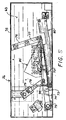
- the plies P 1 and P 2 of the stock material 22 are separated for passage to respective constant entry rollers 43 and 44 as best seen in Fig. 3, which rollers serve as constant entry guides for the respective plies.
- the plies P 1 and P 2 pass between or around separators 45-47.
- the constant entry rollers and separators are mounted between brackets 40.
- one ply P 1 passes to the outer side of the separator nearest the stock roll and the other ply P 2 passes between the other two separators.
- the outermost separators are larger in diameter than the innermost separator.
- the outermost separators are only slightly smaller in diameter than the constant entry rollers.
- the passage of the plies over respective constant entry rollers eliminates a problem that has been encountered in known conversion machines where the multiple plies are passed over a single constant entry roller and then separated for passage between or around separators.
- the frictional grip between the plies and the constant entry rollers aids in preventing overrunning problems.
- the outermost ply may slip relative to the innermost ply, thereby allowing the outer ply to unwind and negating the retarding effect that the constant entry roller desirably has on the plies. This is avoided by passing the plies over their own respective constant entry roller after separation.
- two of the plies may follow the same path around a constant entry roller while the remaining ply travels around the other constant entry roller.
- the middle one of the three plies will be contained between the two outer plies.
- the middle ply travels over the higher one of the two constant entry rollers.
- the inner ply will be separated from its companion ply and passed between the separators 45 and 46.
- the constant entry rollers 43 and 44 are at different elevations, i.e., closer and further from the conversion components 28 and 29 disposed within the machine's housing. Also, the pivot axis 39 of the damper roller pivot arms 38 is located proximately equal distance from the constant entry rollers and thus along a bisector between the constant entry rollers.
- the forming assembly 28 causes inward folding of the lateral edges of the sheet stock material 22 to form a continuous strip having lateral pillow portions and a thinner central band portion.
- the feed/connecting assembly 29, which in the illustrated embodiment includes a pair of cooperating gear-like members 53, pulls the stock material 22 downstream through the machine and also connects the layers along the central band, as by coining and/or perforating in the illustrated preferred embodiment to form a connected strip. As the connected cushioning strip travels downstream from the feed assembly 29, the severing assembly 30 cuts the strip into pads of a desired length.
- the production of dunnage pads by the illustrated machine 12 may be controlled by a controller provided in the housing 26 or in a remote unit.
- a controller provided in the housing 26 or in a remote unit.
- the controller controls operation of a feed motor 52 which drives the feed components and particularly a pair of rotating gear-like members 53.
- the controller also controls operation of a cutter motor 54 and a clutch 56 which drives the severing assembly.
- the cutter motor is continuously operated whereas control of the clutch controls the operation of the severing assembly.
- the functions of the controller may be carried out by a single processor device or by separate devices suitably interfaced to coordinate the operation of the feed motor, cut motor and clutch.
- An exemplary pad produced by the illustrated machine 12 comprises the one or more plies of sheet material that have side portions thereof folded over the center portions thereof to form laterally spaced-apart pillow portions extending along the length of the pad.
- the pillow portions are separated by a central band where lateral edge portions are brought together.
- the lateral edge portions which may be overlapped and/or interleaved, are connected together, and/or to underlying center portions of the plies along the central band.
- the connecting is accomplished by a combination of coining and stitching, the stitching being effected by perforations and/or cut tabs disposed along the central band.
- the housing 26 of the conversion machine 12 has a longitudinal axis corresponding to the direction of passage of the sheet material downstream through the conversion assemblies from a rear or upstream end to a front or downstream end of the machine.
- the housing is generally rectangular in cross-section taken transverse to the longitudinal axis of the machine.
- the machine 12 may be supported in any suitable manner, for example upright, by a stand 57.
- the illustrated forming assembly 28 is of the type described in pending U.S. Patent Application No. 08/386,355 and similar to that shown in U.S. Patent Nos. 5,123,889 and 5,674,172 all of which are hereby incorporated by reference.
- Other forming assemblies are also usable in the practice of the present invention, such as like the form shown in U.S. Patent No. 5,674,172,.
- damper and feed arrangement are particularly advantageous when feeding heavier weights of two ply stock material when the machine is in a vertical orientation, for example, two 70 grams/square meter ply kraft paper from a 400 meter stock roll (two 50 pound basis weight plies of kraft paper).
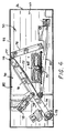
- a post-cutting (exit) guide chute 58 is provided downstream of the severing assembly 30.
- the guide chute 58 includes an upstream converging portion 60 and a downstream tunnel portion 62.
- the converging portion 60 is located between a downstream end plate 63 and an end wall 64 of the housing 26, while the tunnel portion 62 extends through and beyond the end wall 64.
- the guide chute 58 is positioned so that its inlet is aligned with a dunnage outlet opening 65 (Fig. 4) in the end plate 63 at which a pre-cutting guide chute terminates.
- the precutting guide chute extends from a point upstream of the gear-like members 53 to the outlet opening 65, as is known in the art.
- a cut pad will be urged or pushed downstream through the post-cutting guide chute 58 by an approaching dunnage strip
- the converging portion 60 smoothly urges the pad into the tunnel portion 62. As the padpasses through the tunnel portion 62, it is generally constrained circumferentially.
- the severing assembly 30 includes a stationary blade 70 and a moving blade 72, both of which are strategically positioned relative to the dunnage outlet opening 65.
- the blades 70 and 72 are the actual "cutting" elements of the severing assembly and coact in a scissor-like fashion to cut the dunnage strip into cut sections, or pads.
- the stationary blade 70 is fixedly mounted on the frame end plate 63 in such a manner that it is aligned with one side of the dunnage outlet opening 65, which for ease of description will be referred to as the bottom side of the outlet opening.
- the moving blade 72 is part of a moving blade unit 73 which includes a blade support member 74 on which the moving blade 72 is mounted.
- One end of the blade support member 74 is pivotally attached to the end plate 63 by, for example, a bearing block 75.
- the other or distal end of the blade support member 74 is slidably mounted on the end plate 63 within a slanted guide track 76. As is best seen by comparing Figures 4 and 5, this distal end of the blade support member 74 travels back-and-forth within the guide track 76 during a cutting cycle.
- a roller 77 may be attached to the end of the blade support member 74 to facilitate its travel within the guide track 76.
- An intermediate (but not exactly central) part of the blade support member 74 is connected to a drive link 78 which is connected to a drive crank 79.
- a shaft (shown but not specifically numbered) is connected at one end to the drive crank 79. This shaft extends through the end plate 46 for connection by other drive components to the cutter motor 54 via the clutch 56.
- the drive crank 79 is rotated so that the moving blade unit 73 travels between a retracted rest position and an extended full cut position.
- the severing assembly 56 additionally may include an alignment device 80 which automatically "re-aligns" the cut section, or pad, with the dunnage outlet opening and the post-cutting guide chute during the return stroke of the moving blade unit 73. Details of the alignment device are found in U.S. Patent No. 5,569,146.
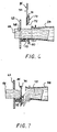
- the moving blade has associated therewith a shutter 85.
- the shutter 85 moves with but trails behind the moving blade 72.
- the shutter cooperates with the moving blade to prevent the leading cut end of the continuous dunnage strip from moving "behind" the moving blade as the moving blade completes it cutting stroke, i.e., moves to its extended position shown in Figs. 5 and 7.
- the cutting blade when its extended full-cut position is almost substantially clear of the outlet opening.
- this allowed the cut end of the continuous dunnage strip 88 sometimes to move behind the moving blade after it has passed by and then interfere with the return stroke of the moving blade.
- Such movement of the cut end of the dunnage strip may arise from relaxation of the dunnage strip 88 particularly along the longitudinal axis of the dunnage strip.
- the shutter functions to block such movement of the cut end behind the dunnage strip, thereby to permit unrestricted return movement of the moving blade to its rest position.
- the shutter 85 includes a shutter plate 90 that is attached at a mounting bar 91 to the back edge of the blade support member 74 by any suitable fastening means.
- the shutter plate is generally triangular in shape so as to fit within the envelope defined by the retracted position of the moving blade 72, the rest position of the crank 79 and link 78, and the top wall 93 of the housing 26.
- the shutter is also of sufficient size to substantially span the outlet opening when the moving blade is in its extended position, thereby preventing any movement of the cut end of the continuous dunnage strip behind the moving blade.
- the shutter has an upstream side surface substantially flush with the upstream side surface of the moving blade.
- the front edge of the shutter plates abuts the back edge of the moving blade to form an essentially continuous smooth surface against with the cut edge of the dunnage strip can easily slide as the cutting blade moves past it in either direction.
- the front downstream corner of the blade support member 74 may be chamfered as shown to facilitate cutting of the dunnage strip 88 to form a cut section or pad 95.
Landscapes
- Making Paper Articles (AREA)
Applications Claiming Priority (2)
| Application Number | Priority Date | Filing Date | Title |
|---|---|---|---|
| US11153798P | 1998-12-09 | 1998-12-09 | |
| US111537P | 1998-12-09 |
Publications (2)
| Publication Number | Publication Date |
|---|---|
| EP1044794A2 true EP1044794A2 (de) | 2000-10-18 |
| EP1044794A3 EP1044794A3 (de) | 2003-07-23 |
Family
ID=22339092
Family Applications (1)
| Application Number | Title | Priority Date | Filing Date |
|---|---|---|---|
| EP99309946A Withdrawn EP1044794A3 (de) | 1998-12-09 | 1999-12-09 | Polsterumwandlungsmaschine und Verfahren zu deren Verwendung mit mehreren Eingangsrollenführungen |
Country Status (2)
| Country | Link |
|---|---|
| US (1) | US7041043B2 (de) |
| EP (1) | EP1044794A3 (de) |
Families Citing this family (10)
| Publication number | Priority date | Publication date | Assignee | Title |
|---|---|---|---|---|
| US20070117703A1 (en) * | 2005-11-22 | 2007-05-24 | Sealed Air Corporation | Machine and method for converting a web of material into dunnage |
| US20090258775A1 (en) * | 2008-04-11 | 2009-10-15 | Chan Simon C S | Apparatus, systems and methods for producing cushioning material |
| WO2015168612A1 (en) | 2014-05-01 | 2015-11-05 | Ranpak Corp. | Machine and method for producing dunnage having an x-shaped cross-sectional profile and dunnage product |
| WO2016137740A1 (en) | 2015-02-26 | 2016-09-01 | Ranpak Corporation | Dunnage conversion system and method for expanding pre-slit sheet stock material |
| US11383475B2 (en) | 2016-05-03 | 2022-07-12 | Ranpak Corp. | Dunnage conversion machine and method |
| CN109715380B (zh) * | 2016-06-30 | 2021-11-26 | 兰帕克公司 | 垫料转换机及垫料转换方法 |
| US20190344523A1 (en) | 2016-10-11 | 2019-11-14 | Sealed Air Corporation (Us) | Machine and method for producing void fill packaging material |
| KR102346801B1 (ko) * | 2017-07-25 | 2022-01-04 | 랜팩 코포레이션 | 더니지 변환 장치 및 방법 |
| JP2024535494A (ja) | 2021-10-01 | 2024-09-30 | クーパー,クレイトン | ダンネージ製造システム |
| JP2025521659A (ja) * | 2022-07-01 | 2025-07-10 | プレジス エルエルシー | 自動供給機能を有するダンネージシステム |
Family Cites Families (17)
| Publication number | Priority date | Publication date | Assignee | Title |
|---|---|---|---|---|
| US3799039A (en) * | 1971-12-14 | 1974-03-26 | Ranpak Corp | Cushioning dunnage mechanism and method |
| US4203270A (en) * | 1978-05-19 | 1980-05-20 | Harold Forman | High speed tear tape applicator for shrink wrap film packaging |
| GB2232951B (en) * | 1989-06-19 | 1993-02-24 | Process Improvements Ltd | Apparatus for producing layered tubes or rings |
| US5088972A (en) * | 1989-11-02 | 1992-02-18 | Eco-Pack Industries, Inc. | Folding and crimping apparatus |
| US5123889A (en) * | 1990-10-05 | 1992-06-23 | Ranpak Corporation | Downsized cushioning dunnage conversion machine and cutting assemblies for use on such a machine |
| US5213867A (en) * | 1990-12-21 | 1993-05-25 | Huston Sr Henry H | Tetrahedral loose-fill packing |
| US5569146A (en) * | 1994-01-28 | 1996-10-29 | Ranpak Corp. | Cushioning conversion machine including a cutting/aligning assembly |
| FI91838C (fi) * | 1993-10-27 | 1994-08-25 | Mercamer Oy | Pakkaustäyte ja laite pakkaustäytteen muodostamiseksi |
| US5593376A (en) * | 1994-07-22 | 1997-01-14 | Ranpak Corp. | Cushioning conversion machine and method |
| FR2734750B1 (fr) * | 1995-05-31 | 1997-11-07 | Naturembal Sa | Dispositif de separation procedant par arrachage |
| US5713825A (en) * | 1995-06-07 | 1998-02-03 | Ranpak Corp. | Cushioning conversion machine and method for converting stock material into a dunnage product having a casing and a stuffing within the casing |
| AU6264196A (en) * | 1995-06-07 | 1996-12-30 | Ranpak Corp. | Machine for converting stock material into a cushioning prod uct |
| CA2225720A1 (en) | 1995-06-26 | 1997-01-16 | Ranpak Corp. | Cushioning conversion machine and method |
| FR2746701B1 (fr) | 1996-03-27 | 1998-06-12 | Naturembal Sa | Machine de fabrication de matelas de rembourrage a systeme de detection de rotation incorrecte du moteur de coupe et de mesure de longueur de matelas produit. |
| US5943844A (en) * | 1996-05-31 | 1999-08-31 | Ross Industries, Inc. | Method of wrapping a food product, packaging machine used and package formed |
| EP0958135A1 (de) * | 1996-06-28 | 1999-11-24 | Ranpak Corp. | Polsterumwandlungsmaschine |
| EP0888878B1 (de) | 1997-06-30 | 2005-09-07 | Ranpak Corp. | Maschine zum Herstellen von Polsterelementen und Verpackungsanlage mit einer solchen Maschine |
-
1999
- 1999-12-09 US US09/453,480 patent/US7041043B2/en not_active Expired - Lifetime
- 1999-12-09 EP EP99309946A patent/EP1044794A3/de not_active Withdrawn
Also Published As
| Publication number | Publication date |
|---|---|
| US20030040416A1 (en) | 2003-02-27 |
| EP1044794A3 (de) | 2003-07-23 |
| US7041043B2 (en) | 2006-05-09 |
Similar Documents
| Publication | Publication Date | Title |
|---|---|---|
| US11325340B2 (en) | Dunnage conversion machine and method | |
| US5785639A (en) | Cushioning conversion machine for making a cushioning product having a shell and stuffing formed from separate plies | |
| US6974407B2 (en) | Cushioning conversion machine and method | |
| EP0888879A1 (de) | Polsterumwandlungsmaschine,Verfahren und Produkt | |
| CA2494020A1 (en) | Compact apparatus and system for creating and dispensing cushioning dunnage | |
| EP1047545B1 (de) | Maschine und verfahren zum herstellen von polsterelementen | |
| US6168560B1 (en) | Cushioning conversion machine and method with pad transferring device | |
| US7041043B2 (en) | Cushioning conversion machine and method with plural constant entry rollers and moving blade shutter | |
| US5569146A (en) | Cushioning conversion machine including a cutting/aligning assembly | |
| US6402674B1 (en) | Cushioning conversion system and method with dancer roller cart | |
| US6217501B1 (en) | Cushioning conversion machine | |
| US6491614B1 (en) | Cushioning conversion machine with tension control | |
| US7083560B2 (en) | Cushioning conversion machine having heavy duty characteristics | |
| EP3930993B1 (de) | Formungsanordnung für eine packmaterialumwandlungsmaschine | |
| EP0831992A1 (de) | Vorrichtung zum umformen von rohmaterial in polstermaterial | |
| EP0998384B1 (de) | Polsterkonvertierungsmaschine mit mechanischer zufuhr | |
| US5735784A (en) | Loading assembly for a cushioning conversion machine | |
| US20070021286A1 (en) | Cushioning conversion machine having heavy duty characteristics | |
| US20250170796A1 (en) | Dunnage device with tag-tearing prevention | |
| EP0747208A1 (de) | Polsterumwandlungsmaschine mit einem Papierformungsrad | |
| WO2000027620A1 (en) | Cushioning conversion machine and method |
Legal Events
| Date | Code | Title | Description |
|---|---|---|---|
| PUAI | Public reference made under article 153(3) epc to a published international application that has entered the european phase |
Free format text: ORIGINAL CODE: 0009012 |
|
| AK | Designated contracting states |
Kind code of ref document: A2 Designated state(s): AT BE CH CY DE DK ES FI FR GB GR IE IT LI LU MC NL PT SE |
|
| AX | Request for extension of the european patent |
Free format text: AL;LT;LV;MK;RO;SI |
|
| PUAL | Search report despatched |
Free format text: ORIGINAL CODE: 0009013 |
|
| AK | Designated contracting states |
Designated state(s): AT BE CH CY DE DK ES FI FR GB GR IE IT LI LU MC NL PT SE |
|
| AX | Request for extension of the european patent |
Extension state: AL LT LV MK RO SI |
|
| AKX | Designation fees paid |
Designated state(s): CH DE FR GB LI NL |
|
| STAA | Information on the status of an ep patent application or granted ep patent |
Free format text: STATUS: THE APPLICATION IS DEEMED TO BE WITHDRAWN |
|
| 18D | Application deemed to be withdrawn |
Effective date: 20040124 |