EP1044837A2 - Toit de véhicule équipé avec un élément de toit coulissant - Google Patents
Toit de véhicule équipé avec un élément de toit coulissant Download PDFInfo
- Publication number
- EP1044837A2 EP1044837A2 EP00108155A EP00108155A EP1044837A2 EP 1044837 A2 EP1044837 A2 EP 1044837A2 EP 00108155 A EP00108155 A EP 00108155A EP 00108155 A EP00108155 A EP 00108155A EP 1044837 A2 EP1044837 A2 EP 1044837A2
- Authority
- EP
- European Patent Office
- Prior art keywords
- vehicle
- vehicle roof
- roof according
- clamping part
- locking
- Prior art date
- Legal status (The legal status is an assumption and is not a legal conclusion. Google has not performed a legal analysis and makes no representation as to the accuracy of the status listed.)
- Granted
Links
- 230000000903 blocking effect Effects 0.000 claims abstract description 67
- 230000033001 locomotion Effects 0.000 claims abstract description 51
- 230000008859 change Effects 0.000 claims abstract description 21
- 238000006073 displacement reaction Methods 0.000 claims description 12
- 230000007246 mechanism Effects 0.000 claims description 5
- 239000006260 foam Substances 0.000 claims description 4
- 230000001133 acceleration Effects 0.000 description 6
- 230000008901 benefit Effects 0.000 description 5
- 208000027418 Wounds and injury Diseases 0.000 description 3
- 230000005540 biological transmission Effects 0.000 description 3
- 239000002131 composite material Substances 0.000 description 3
- 230000006378 damage Effects 0.000 description 3
- 230000005484 gravity Effects 0.000 description 3
- 208000014674 injury Diseases 0.000 description 3
- 230000004044 response Effects 0.000 description 3
- 230000003247 decreasing effect Effects 0.000 description 2
- 230000001934 delay Effects 0.000 description 2
- 230000003111 delayed effect Effects 0.000 description 2
- 239000002783 friction material Substances 0.000 description 2
- 230000007704 transition Effects 0.000 description 2
- 241000446313 Lamella Species 0.000 description 1
- 206010041662 Splinter Diseases 0.000 description 1
- 230000004888 barrier function Effects 0.000 description 1
- 230000008878 coupling Effects 0.000 description 1
- 238000010168 coupling process Methods 0.000 description 1
- 238000005859 coupling reaction Methods 0.000 description 1
- 238000013016 damping Methods 0.000 description 1
- 230000001066 destructive effect Effects 0.000 description 1
- 230000005489 elastic deformation Effects 0.000 description 1
- 238000000926 separation method Methods 0.000 description 1
Images


Classifications
-
- B—PERFORMING OPERATIONS; TRANSPORTING
- B60—VEHICLES IN GENERAL
- B60J—WINDOWS, WINDSCREENS, NON-FIXED ROOFS, DOORS, OR SIMILAR DEVICES FOR VEHICLES; REMOVABLE EXTERNAL PROTECTIVE COVERINGS SPECIALLY ADAPTED FOR VEHICLES
- B60J7/00—Non-fixed roofs; Roofs with movable panels, e.g. rotary sunroofs
- B60J7/02—Non-fixed roofs; Roofs with movable panels, e.g. rotary sunroofs of sliding type, e.g. comprising guide shoes
- B60J7/04—Non-fixed roofs; Roofs with movable panels, e.g. rotary sunroofs of sliding type, e.g. comprising guide shoes with rigid plate-like element or elements, e.g. open roofs with harmonica-type folding rigid panels
- B60J7/047—Non-fixed roofs; Roofs with movable panels, e.g. rotary sunroofs of sliding type, e.g. comprising guide shoes with rigid plate-like element or elements, e.g. open roofs with harmonica-type folding rigid panels movable to overlapping or nested relationship
-
- B—PERFORMING OPERATIONS; TRANSPORTING
- B60—VEHICLES IN GENERAL
- B60J—WINDOWS, WINDSCREENS, NON-FIXED ROOFS, DOORS, OR SIMILAR DEVICES FOR VEHICLES; REMOVABLE EXTERNAL PROTECTIVE COVERINGS SPECIALLY ADAPTED FOR VEHICLES
- B60J7/00—Non-fixed roofs; Roofs with movable panels, e.g. rotary sunroofs
- B60J7/02—Non-fixed roofs; Roofs with movable panels, e.g. rotary sunroofs of sliding type, e.g. comprising guide shoes
- B60J7/04—Non-fixed roofs; Roofs with movable panels, e.g. rotary sunroofs of sliding type, e.g. comprising guide shoes with rigid plate-like element or elements, e.g. open roofs with harmonica-type folding rigid panels
- B60J7/057—Driving or actuating arrangements e.g. manually operated levers or knobs
Definitions
- the invention relates to a vehicle roof with a movable Roof element according to the preamble of claim 1.
- a vehicle roof is known, the one A number of lamellar roof elements arranged one behind the other has, which in a roof opening in side guide rails Slidably mounted in the vehicle's longitudinal direction are.
- the roof elements are flat against one another and close the roof opening to open the roof one or more roof elements are pivoted and in pivoted position pushed together.
- the roof elements are in the fully pivoted position against it uncoupled.
- the guidance of the roof elements in the guide rails takes place via guide carriages with the roof elements are connected and after the complete swing out and decoupling the roof elements with the aid of locking elements can be firmly locked with the roof-mounted guide rail are by the locking elements in locking openings snap into the guide rail.
- the locking is called kinematic Forced control depending on the pivoting movement of the Roof elements executed so that locking only takes place when the roof panels are in the fully flared position to reach. If the locking mechanism is faulty, can lock the locking elements in the locking openings the guide rail cannot be guaranteed safely, so that in the event of a fault in the kinematics, the vehicle occupants basically in every open position of the roof elements - independent from the swivel position of the roof elements - at one Accident are at increased risk of injury.
- Another sunroof with two slidable in a roof opening arranged roof elements is from DE 197 56 020 C1 known.
- This sunroof is with a crash protection provided to prevent mechanical parts in the event of an accident of the sunroof and adjacent frame parts through the large deceleration forces are destroyed from the vehicle solve and pose a risk to vehicle occupants and others become a road user.
- the crash protection consists of one Brake mechanism for the roof elements, which acts as a deformable stop is formed in the guide rail of the roof elements. In the event of a crash, the roof elements hit at high speed on the stop, which is part of the kinetic energy converted into deformation work.
- the invention is based on the problem with vehicle roofs with at least one displaceable in the longitudinal direction of the vehicle Roof element increases the risk of injury with simple measures reduce.
- the locking device designed according to the invention is the result mass forces acting on them in response to a change in speed, especially a delay, from the shift position, in which an unimpeded movement of the roof elements is possible in the guide rail, in the blocking position transferred in the movement in the guide rail is prevented or at least braked sharply.
- a roof element or several translationally movable in the guide rail Roof elements are effectively braked by the locking device or blocked, especially before reaching one significant speed relative to the guide rail, so that in the event of a crash, a high pulse transmission, which associated with a corresponding destructive power avoided can be.
- the shift position into the blocking position takes place regardless of a kinematic, on the roof elements acting adjusting mechanism only under the influence of the Barrier acting mass forces such as deceleration or Acceleration forces. There is no dependence on the actuating movement the locking device on the functionality of the Kinematics of the roof elements, making security essential is increased.
- the locking device is indeed after exceeding the speed change limit, however, before the start or at the latest at Start of movement of the roof element, which is in response to the inertial forces acting on the vehicle take place in the blocking position transferred.
- this version there is a relative movement of the roof element for the vehicle body and the guide rails effectively prevented or at least largely reduced, even in the event that the drive cable of the Roof element tears, which in the intact condition of the vehicle roof a kinematic positive guidance of the longitudinal movement of the Roof element caused in the guide rails of the vehicle roof.
- the roof element or elements blocked or slowed down at a time before it a high, unintentional relative movement between the roof element and guide rail can arise.
- the blocking forces can both come directly from the guide rail as well as from another vehicle-fixed component be included.
- the locking device is also advantageous how the roof elements are slidably mounted in the guide rail, so that blocking of the locking device immediately leads to the fixing of the roof elements.
- the Locking device in the blocking position by means of the influence of friction is fixed in the guide rail, so that on locking openings in the guide rail and a corresponding design the locking device or other locking elements can be.
- the guide rail gives the advantage that the locking device fixed in any position in the guide rail can be. It is not necessary that the locking device certain discrete positions reached. Hereby the braking distance of the locking device and also the braking distance the roof elements shortened.
- the locking device can also be advantageous to have discrete locking positions to be provided for the locking device in which the Locking device engages in blocking position.
- the locking device is positive in the blocking position on the vehicle body or one permanently connected to the body Component, especially the guide rail for the Roof element, held.
- the form fit offer the advantage that maximum power transmission is possible.
- the locking device is preferably constructed in two parts and has a guide part and an adjustable relative to the guide part Clamping part, which in regular operation in the the movement of the locking device does not restrict the displacement position stands and when the speed change limit is exceeded is transferred into the blocking position.
- the clamping part which is both translational and rotational as well as mixed translational / rotary relative to the guide part can be kept movable, is preferably about a locking member, which is part of the locking device, in the blocking position transferred and / or held in the blocking position.
- the locking member is above mass forces as a result of the change in speed above the permitted limit of a release position, in which the clamping part without hindrance from Locking element is in the shift position and only from the roof drive is loaded into a locking position in which the Clamping part is blocked or braked, transferable.
- the locking device connected to the roof element constructed in three parts and includes the guide part, the Clamping part and the locking member, wherein the clamping part and locking member are functionally separated by the locking member immediately above the change in speed from the release position to the locking position is transferred and in the locking position Clamping part is applied in the direction of the blocking position.
- the clamping part can be force-loaded in the direction of its blocking position his.
- the clamping part is over the one in the release position Locking member advantageously held in the shift position; once the locking member under the impression of the inertial forces arrives in the locking position, the clamping part as a result of Force applied in blocking position.
- the application of force can both via an additional force element, for example a spring, as well as by the weight of the Clamping part done. If necessary, the clamping member also directly in the blocking position from the locking member or in Blocked position held.
- the locking member is in the case of a Crashes prefer to experience a change in speed, which is mainly directed in the direction of travel, and can accordingly advantageously a relative movement in the direction of travel run against the guide part, whereas the clamping part for power transmission from the roof element to the vehicle body or the guide rail expediently has a relative movement a component perpendicular to the movement of the locking member can.
- the locking member is advantageous in the direction of its read position acted upon in particular by a spring, the Expedient force of the speed change occurring in an accident is opposite, so that about the spring parameters the speed change limit, when exceeded the longitudinal movement of the roof element is blocked, can be specified.
- a stop can be provided on the guide part, on which the Locking element when the speed change limit value is exceeded drives up to the relative movement of the locking member limit.
- the advantage is achieved that at decreasing mass forces acting on the locking member Locking element under the influence of spring force in its original Moves back position, the clamping part in the meantime has taken its blocking position and now by the retracted locking member fixed in the blocking position can be.
- the clamping part is in a first preferred embodiment adjustable clamping pin formed, in particular by a trained as a locking pin locking member.
- the clamping pin is moved by the expansion pin and against the structure or the guide rail of the roof element pressed, whereby a blocking the locking device Clamping force is generated.
- the clamping part is in a second preferred embodiment Locking lever formed, which is advantageously pivotally mounted and in particular with one in the direction of its blocking position acting force is applied, for example a bearing axis extending outside the center of gravity is provided around which the locking lever can pivot.
- the guide part has one in the vehicle longitudinal direction inclined sliding track for the advantageous sliding movement of the clamping part between the shift position and blocking position.
- the transfer track preferably increases in such a way that that of the front of the vehicle facing end section of the sliding track higher lies as the end section facing away from the front of the vehicle.
- the clamping part, the additional or alternative to the version as a locking lever or as a clamping pin as in the longitudinal direction movable wedge can be formed is in Shift position at the lowest point of the shift path in one held stable position; in response to a change in speed the clamping part leaves above the limit value the lowest point of the sliding track and rises against it Weight force towards the top, the blocking position marking end section of the plane, which is particularly inclined trained sliding track.
- a transfer movement on the locking device is advantageous damping buffer element provided in blocking position, which ensures that the clamping part due to vibrations, small bumps or the like not accidentally in the blocking position is transferred.
- the buffer element lies in particular in the path of movement between the shift position and the blocking position and is expediently connected to the clamping part.
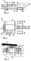
- the vehicle roof 1 shown in FIGS. 1 and 2 for a vehicle, in particular a motor vehicle, has two roof elements 2 and 3, which are arranged displaceably in the vehicle longitudinal direction 4 are between a closed position in which the Roof opening of the vehicle is closed, and an open position, in which the roof opening is at least partially open, can be adjusted.
- the roof elements 2 and 3 are as Roof slats formed in addition to the transitional Shifting movement in the vehicle longitudinal direction 4 also one Swiveling movement about a transverse axis, which is orthogonal in the transverse direction runs to the longitudinal direction 4 of the vehicle.
- the open position of the vehicle roof 1 can be pivoted the roof elements 2 and 3 about the transverse axis and / or by translatory displacement in the vehicle longitudinal direction 4 can be achieved.
- the roof elements 2 and 3 form at least in phases a composite that translationally shifted as a unit can be. If necessary, this composite can be used during the transfer in the open position depending on the position of the individual Roof elements 2 and 3 are also lifted so that the roof elements independently pivoted or shifted can be.
- the roof elements are slides 5 or 6 assigned to both sides of the Vehicle on the roof elements 2 and 3 for guiding the roof elements in vehicle-mounted guide rails (see Fig. 5, reference numerals 17) are slidably guided.
- Each roof element is assigned a guide carriage on both sides of the vehicle.
- the guide carriage 5 between the two adjacent Roof elements 2 and 3 allow depending on the current state of motion both a translational Forced coupling as well as independent pivoting of the individual Roof elements 2 and 3. If necessary, additional roof elements in front of the roof element seen in the direction of travel 2 or arranged behind the subsequent roof element 3.
- the guide carriage 6 also takes on the function of a Locking device 7, which depends on the currently on Vehicle acting acceleration or deceleration forces between a shift position in which the locking device 7 is held freely displaceably in the guide rail, and a blocking position in which the movement of the locking device 7 and the roof elements 2 and 3 is blocked, adjustable is.
- the locking device 7 is used in the case of a very strong deceleration of the vehicle as a safety component Locking of the lamella composite formed from two roof elements 2 and 3, to prevent that the roof elements in one Accident with great force against the front roof opening limitation bounce and a hand or arm of a vehicle occupant is injured in the roof opening by the roof elements.
- the locking device 7 is expediently constructed so that when exceeded a deceleration limit applied to the vehicle an automatic transfer of shift position takes place in the blocking position. Since the locking device 7 in Movement space of the sliding movement of the roof elements 2 and 3 lies, these are locked in the vehicle longitudinal direction 4, if the locking device 7 is in the blocking position, whereby a further relative displacement of the roof elements over the Vehicle is prevented.
- the locking device can be located behind in the direction of travel as well as lying in front in the direction of travel. Furthermore, it may be appropriate to provide a locking device both when a delay limit is exceeded as well as when an acceleration limit is exceeded is placed in the blocking position. Where applicable at least two in opposite directions of acceleration or deceleration appealing locking devices provided.
- the locking device 7 consists of a guide part 8 and a wedge-shaped clamping part 9.
- the guide part 8 is used to guide the locking device 7 in the vehicle fixed Guide rail that is movable relative to the guide part 8 held clamping part 9 takes over the function of a Locking device, depending on the current vehicle deceleration adjusted between the shift position and the blocking position can be.
- the guide part 8 has an enclosed recess 10 on, the bottom of which is a sliding track 11 forms on which the clamping part 9 between the shift position and blocking position can be moved.
- the sliding track 11 is designed as an inclined plane, towards the front of the vehicle - lying on the right in Fig.
- Both the shift position as the blocking position is also a vertical one Wall section of the guide part 8 limited.
- the roof elements move including the guide carriage and the guide part of the locking device due to the inertia with the original velocity of the vehicle, but less by an amount that by the friction in the guide rail and one by the Drive the roof elements, the sudden, external changes in speed counteracts, is determined.
- the clamping part 9 on the other hand, there is only minimal friction in the shift position and is driven by the roof structure in in no way restricted in movement. The clamping part 9 retains hence largely its original speed at, whereas the guide member 8 is delayed, so that Clamping part 9 experiences an acceleration relative to the guide part 8.
- the clamping part 9 is thereby able to reduce the friction in to overcome its position at the lower end of the sliding track 11 and against the weight, the inclined plane up to To reach the upper blocking position to slide diagonally upwards.
- the clamping part 9 is jammed with one vehicle-fixed component and causes in this way Fixing the guide part 8 and all other components of the roof structure which are mounted in a longitudinally displaceable manner.
- the deceleration limit is primarily determined by determines the angle of inclination ⁇ of the sliding track 11, which in Embodiment shown is about 7 °. With a low-friction Material pairing can be a larger one, with higher friction Material pairings selected a lower angle of inclination become.
- the clamping part 9 is wedge-shaped and tapers in increasing direction of the sliding track 11.
- the wedge shape compensates for the inclination of the sliding track, so that the top 12 of the clamping part 9 held parallel to the guide rail 17 is in which the guide member 8 is slidably mounted.
- a foam buffer element 13 is provided, which above the clamping part 9 in the recess 10 of the guide part 8 is held and in particular attached to the guide part 8 is.
- the buffer element 13 lies in the path of movement of the Clamping part 9 and has a dampening influence on the transfer movement the clamping part 9 from the shift position into the blocking position, which prevents small bumps or vibrations to undesirably block the roof structure to lead.
- a Sliding shoe 14 attached in a guide channel of the guide rail 17 to stabilize the displacement movement of the Locking device 7 is guided with low friction. Furthermore comes the slide shoe 14 in the blocking position of the clamping part 9 also the function of a counterhold. 5 lies the clamping part 9 in the blocking position on an upper edge 18 of the Guide rail 17, the top of the clamping part due the wedge shape is parallel to the upper edge 18.
- the slide shoe 14 fills the space above the upper edge in the guide channel, so that the upper edge also below the pressure of the clamping part 9 cannot escape upwards.
- the locking device 7 is also a guide carriage trained for a roof element and is about a Drive cable 20 in a cable receptacle 21 of the locking device 7 is fixed in one with the vehicle body connected guide rail 17 held longitudinally displaceable.
- the Guide rail 17 has latching openings at regular intervals 30 on.
- the locking device 7 is constructed in several parts and comprises a guide part 8, which is basically about the drive cable 20 positively guided to open and close the roof is, as well as a clamping part 9, which is between the shift position (Fig. 6) and blocking position (Fig.
- the clamping part 9 is designed as a locking lever 19 which a bearing axis 25 is connected to the guide part 8 and in a longitudinal plane including the direction of travel 24 of FIG Locking device 7 is held pivotably.
- a section the locking lever 19 is in contact with a locking member 22, that is movable in a recess 10 in the guide part 8, in particular longitudinally displaceable, held and opposed by one to the direction of travel 24 return spring 23 with a spring force is applied.
- the bearing axis 25 of the locking lever 19 is mounted outside the locking lever center of gravity, the center of gravity in the shift position shown in FIG.
- the longitudinally movable locking member 22 is in the recess 10 in the guide part 8 between one shown in Fig. 6 Release position in which the locking lever 19 in a Movement of the guide carriage does not impair the shifted position located, and a locking position (Fig. 7, 8) adjustable, in which the locking lever 19 in the blocking position stands. 6, the guide carriage and the roof element arranged above it by a movement of the Drive cable 20 can be adjusted along the guide rail 17.
- the force of the return spring 23 acts counter to the direction of travel 24 and holds the locking member 22 in the release position, wherein the return spring 23 is dimensioned in such a way that the vehicle delays occurring in regular driving are unable to remove the locking member from the release position to move out.
- the direction of travel 24 is opposite End face of the locking member 22 in contact with an in the recess 10 protruding portion of the locking lever 19th
- the locking member engages in a bulge 26 of the locking lever 19, see Fig. 9, and thereby holds the locking lever 19 in the shift position.
- the drive cable 20 initially holds the guide part 8 in position with respect to the vehicle body, so that the guide member 8th initially the same delay as the vehicle body experiences.
- the locking member 22 retains due to its longitudinal displaceability compared to the guide part 8 its speed at and is against the force of the return spring 23 against the front wall in the direction of travel 24 of the recess 22 pressed, whereby a facing the locking lever 19 Guide pin 28 of the locking member 22 out of engagement with the bulge 27 on the locking lever 19.
- FIG. 8 shows the locking device 7 in a subsequent to FIG. 7 Phase of the crash.
- the jerky initial delay 7 has decreased so that the force of the return spring 23rd is again able to act on the locking member 22, the is still in the blocking position.
- the locking link 22 reaches with its free end face into the upper bulge 26 of the locking lever 19, whereby the blocking position of the Locking lever 19 is fixed.
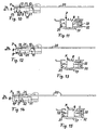
- FIGS. 10 to 15 is another embodiment of a Locking device 7 shown, FIGS. 10 and 11 the locking device 7 in the shift position, FIGS. 12 and 13 the transition from the shift position into the blocking position and 14 and 15, the blocking position of the locking device demonstrate.
- the locking device 7 consists of the guide part 8, the over the cable receptacle 21 is firmly connected to the drive cable 20 and the clamping part 9, which has a wedge 31 and a clamping pin 32 comprises, both in the recess 10 in the guide part 8 are arranged and a relative movement relative to the Can exercise part 8.
- the bottom of the recess 10 is formed by a sliding track 11 which is opposite to the direction of travel 24 rises and on which the wedge 31 in the longitudinal direction the vehicle is slidably mounted.
- the pin 32 is held in a bore in the wedge 31, the clamping pin 32 Transversely to the direction of travel 24 slidably mounted in the wedge 31.
- a locking member 22 designed as an expansion pin is arranged, which is slidably received in a longitudinal bore of the wedge 31 is.
- the longitudinal bore of the locking member 22 cuts the Axis of the transverse clamping pin 32, the length of the Locking member 22 is dimensioned in such a way that at a complete the transverse bore in the locking member received in the longitudinal bore for the clamping pin 32 is reached or crossed.
- the locking member 22 abuts in that shown in FIGS. 10, 11 Shifting position to the inner wall facing the direction of travel 24 the recess 10, which is a stop for the locking member 22 forms.
- the clamping pin 32 projects transversely to the longitudinal direction of the vehicle out of the wedge 31 on one side of the wedge.
- the clamping pin has a conical tip that one Side wall 33 of the guide rail 17 faces in the shown displacement position but at a distance from the side wall 33 lies.
- the wedge 31 is the formed as an inclined plane sliding path 11 of the recess 10 completely pushed up, whereby to dampen the vertical movement of the wedge 31 to a foam buffer element 13 the top of the recess 10 is provided on the guide part 8 is.
- the locking member 22 is still in the bore in Wedge 31, the clamping pin 32 is accordingly still on the Side wall 33 of the guide rail 17.
- the locking device 7 is in the in 10 and 11 shown displacement position in which the locking member 22 protrudes from the hole in the wedge 31, the clamping pin 32 with Distance to the side wall 33 of the guide rail 17 is and consequently a movement that also functions as a guide carriage locking device in the guide rail is not inhibited.
- the guide part 8 initially held by the drive cable 20.
- the guide part 8 due to the high deceleration forces acting on the vehicle accelerated again in the direction of travel 24, the Clamping part 9, on the other hand, takes due to the clamping pin 32 generated clamping force not on the longitudinal movement of the guide member 8 parts, but keeps its position in the longitudinal direction at.
- the longitudinal acceleration of the guide part 8 relative to Clamping part 9 causes the wedge 31 of the clamping part 9 the inclined plane of the sliding track 11 pressed vertically upwards until the foam buffer element 13 is reached dampened top of the recess 10.
- the blocking position in the lateral sections of the Wedge 31 pressed against an upper edge 16 of the guide rail 17 be so that the wedge 31 with high force against the The guide rail is braked, see Fig. 15. Since in the blocking position the rear end of the wedge 31 against the rear Inner wall of the recess 10 is pressed, the Movement of the guide part 8 and the movement of the with the guide part 8 connected roof element blocked.
Landscapes
- Engineering & Computer Science (AREA)
- Mechanical Engineering (AREA)
- Fittings On The Vehicle Exterior For Carrying Loads, And Devices For Holding Or Mounting Articles (AREA)
Applications Claiming Priority (4)
| Application Number | Priority Date | Filing Date | Title |
|---|---|---|---|
| DE19916672 | 1999-04-14 | ||
| DE19916672A DE19916672C1 (de) | 1999-04-14 | 1999-04-14 | Fahrzeugdach mit einem verschiebbaren Deckelelement |
| DE19934847 | 1999-07-24 | ||
| DE19934847A DE19934847C2 (de) | 1999-04-14 | 1999-07-24 | Fahrzeugdach mit einem verschiebbaren Dachelement |
Publications (3)
| Publication Number | Publication Date |
|---|---|
| EP1044837A2 true EP1044837A2 (fr) | 2000-10-18 |
| EP1044837A3 EP1044837A3 (fr) | 2002-01-09 |
| EP1044837B1 EP1044837B1 (fr) | 2003-06-18 |
Family
ID=26052890
Family Applications (1)
| Application Number | Title | Priority Date | Filing Date |
|---|---|---|---|
| EP20000108155 Expired - Lifetime EP1044837B1 (fr) | 1999-04-14 | 2000-04-13 | Toit de véhicule équipé avec un élément de toit coulissant |
Country Status (1)
| Country | Link |
|---|---|
| EP (1) | EP1044837B1 (fr) |
Cited By (4)
| Publication number | Priority date | Publication date | Assignee | Title |
|---|---|---|---|---|
| EP1905631A1 (fr) | 2006-09-27 | 2008-04-02 | ArvinMeritor GmbH | Dispositif de freinage de sécurité pour le panneau d'un toit ouvrant |
| FR2940934A1 (fr) * | 2009-01-14 | 2010-07-16 | Peugeot Citroen Automobiles Sa | Vehicule automobile comprenant un toit ouvrant monte mobile sur le pavillon de ce vehicule |
| DE102011102895A1 (de) * | 2011-05-31 | 2012-12-06 | GM Global Technology Operations LLC (n. d. Gesetzen des Staates Delaware) | Rückhaltevorrichtung, Beschattungssystem, Kraftfahrzeug und Verfahren hierzu |
| EP3569432A1 (fr) * | 2018-05-15 | 2019-11-20 | Volvo Car Corporation | Prévention d'ouverture de toit de véhicule en cas de collision |
Families Citing this family (1)
| Publication number | Priority date | Publication date | Assignee | Title |
|---|---|---|---|---|
| DE112019006626B4 (de) * | 2019-01-11 | 2024-11-28 | Bos Gmbh & Co. Kg | Antriebssystem für ein bewegliches Dachteil eines Dachmoduls eines Kraftfahrzeugs |
Citations (1)
| Publication number | Priority date | Publication date | Assignee | Title |
|---|---|---|---|---|
| DE19608916C1 (de) | 1996-03-07 | 1997-04-17 | Webasto Karosseriesysteme | Fahrzeugdach mit einer Folge von ausstellbaren Deckelelementen |
Family Cites Families (3)
| Publication number | Priority date | Publication date | Assignee | Title |
|---|---|---|---|---|
| AU668948B2 (en) * | 1992-07-03 | 1996-05-23 | Zani S.R.L. | Locking device for roofs of motor-vehicles or the like |
| DE19756020C1 (de) * | 1997-12-17 | 1999-01-07 | Webasto Karosseriesysteme | Schiebedach |
| DE19836853C1 (de) * | 1998-08-14 | 2000-03-09 | Daimler Chrysler Ag | Dachanordnung an Fahrzeugen |
-
2000
- 2000-04-13 EP EP20000108155 patent/EP1044837B1/fr not_active Expired - Lifetime
Patent Citations (1)
| Publication number | Priority date | Publication date | Assignee | Title |
|---|---|---|---|---|
| DE19608916C1 (de) | 1996-03-07 | 1997-04-17 | Webasto Karosseriesysteme | Fahrzeugdach mit einer Folge von ausstellbaren Deckelelementen |
Cited By (6)
| Publication number | Priority date | Publication date | Assignee | Title |
|---|---|---|---|---|
| EP1905631A1 (fr) | 2006-09-27 | 2008-04-02 | ArvinMeritor GmbH | Dispositif de freinage de sécurité pour le panneau d'un toit ouvrant |
| US7523983B2 (en) | 2006-09-27 | 2009-04-28 | Arvinmeritor Technology, Llc | Safety braking device of a sliding roof cover |
| FR2940934A1 (fr) * | 2009-01-14 | 2010-07-16 | Peugeot Citroen Automobiles Sa | Vehicule automobile comprenant un toit ouvrant monte mobile sur le pavillon de ce vehicule |
| WO2010081952A1 (fr) | 2009-01-14 | 2010-07-22 | Peugeot Citroën Automobiles SA | Vehicule automobile comprenant un toit ouvrant monte mobile sur le pavillon de ce vehicule |
| DE102011102895A1 (de) * | 2011-05-31 | 2012-12-06 | GM Global Technology Operations LLC (n. d. Gesetzen des Staates Delaware) | Rückhaltevorrichtung, Beschattungssystem, Kraftfahrzeug und Verfahren hierzu |
| EP3569432A1 (fr) * | 2018-05-15 | 2019-11-20 | Volvo Car Corporation | Prévention d'ouverture de toit de véhicule en cas de collision |
Also Published As
| Publication number | Publication date |
|---|---|
| EP1044837B1 (fr) | 2003-06-18 |
| EP1044837A3 (fr) | 2002-01-09 |
Similar Documents
| Publication | Publication Date | Title |
|---|---|---|
| DE2719325C2 (de) | Verschluss für Sicherheitsgurte | |
| EP2200702B1 (fr) | Coulisseau de sécurité pour système de protection contre les chutes | |
| EP3390201B1 (fr) | Colonne de direction pour un véhicule automobile | |
| EP3484327B1 (fr) | Dispositif d'entraînement d'un élément de meuble mobile, et procédé d'ouverture et de fermeture d'un élément de meuble mobile | |
| DE102014108577B3 (de) | Lenksäule für ein Kraftfahrzeug | |
| DE102004051060B3 (de) | Verstellbare Lenksäule eines Kraftfahrzeuges | |
| DE19756020C1 (de) | Schiebedach | |
| DE10003853A1 (de) | Fahrzeugsitz mit einer beweglichen Sicherheitstraverse | |
| EP1319886A2 (fr) | Dispositif de protection pour machines telles que presses-plieuses, découpeuses, machines à éstamper ou analogues | |
| DE102005009949A1 (de) | Vorrichtung und Verfahren zur Verminderung der Folgen eines Auffahrunfalls eines Fahrzeugs auf ein Hindernis | |
| WO2008052506A1 (fr) | Toit coulissant | |
| EP1044837B1 (fr) | Toit de véhicule équipé avec un élément de toit coulissant | |
| EP0805075B1 (fr) | Dispositif de réglage d'un renvoi de ceinture | |
| EP1541425A1 (fr) | Dispositif de maintien pour un dispositif de sécurité d'un véhicule | |
| DE19934847C2 (de) | Fahrzeugdach mit einem verschiebbaren Dachelement | |
| DE10340673A1 (de) | Sicherheitsverriegelungsvorrichtung für ein Behältnis in einem Fahrzeug | |
| DE10040044B4 (de) | Bremsvorrichtung für einen Schiebedachdeckel | |
| DE4441020C1 (de) | Stoßdämpfervorrichtung für Laufwagen insbesondere für Folienreckanlagen | |
| DE10343399B3 (de) | Lenksäulenanordnung | |
| DE10232795A1 (de) | Schutzeinrichtung für Maschinen, wie Biegepressen, Schneidemaschinen, Stanzmaschinen oder dergleichen | |
| DE29912977U1 (de) | Fahrzeugdach mit einem verschiebbarem Deckelelement | |
| EP1905631B1 (fr) | Dispositif de freinage de sécurité pour le panneau d'un toit ouvrant | |
| EP0853028A1 (fr) | Dispositif de réglage du renvoi latéral d'un système de ceinture de sécurité de véhicule | |
| DE19916672C1 (de) | Fahrzeugdach mit einem verschiebbaren Deckelelement | |
| WO2004076248A1 (fr) | Limiteur d'effort pour ceinture de securite |
Legal Events
| Date | Code | Title | Description |
|---|---|---|---|
| PUAI | Public reference made under article 153(3) epc to a published international application that has entered the european phase |
Free format text: ORIGINAL CODE: 0009012 |
|
| AK | Designated contracting states |
Kind code of ref document: A2 Designated state(s): AT BE CH CY DE DK ES FI FR GB GR IE IT LI LU MC NL PT SE Kind code of ref document: A2 Designated state(s): DE FR GB IT |
|
| AX | Request for extension of the european patent |
Free format text: AL;LT;LV;MK;RO;SI |
|
| PUAL | Search report despatched |
Free format text: ORIGINAL CODE: 0009013 |
|
| AK | Designated contracting states |
Kind code of ref document: A3 Designated state(s): AT BE CH CY DE DK ES FI FR GB GR IE IT LI LU MC NL PT SE |
|
| AX | Request for extension of the european patent |
Free format text: AL;LT;LV;MK;RO;SI |
|
| RIC1 | Information provided on ipc code assigned before grant |
Free format text: 7B 60J 7/057 A, 7B 60J 7/047 B |
|
| 17P | Request for examination filed |
Effective date: 20011211 |
|
| GRAG | Despatch of communication of intention to grant |
Free format text: ORIGINAL CODE: EPIDOS AGRA |
|
| 17Q | First examination report despatched |
Effective date: 20020510 |
|
| GRAG | Despatch of communication of intention to grant |
Free format text: ORIGINAL CODE: EPIDOS AGRA |
|
| GRAH | Despatch of communication of intention to grant a patent |
Free format text: ORIGINAL CODE: EPIDOS IGRA |
|
| GRAH | Despatch of communication of intention to grant a patent |
Free format text: ORIGINAL CODE: EPIDOS IGRA |
|
| AKX | Designation fees paid |
Free format text: DE FR GB IT |
|
| RBV | Designated contracting states (corrected) |
Designated state(s): DE FR GB IT |
|
| GRAA | (expected) grant |
Free format text: ORIGINAL CODE: 0009210 |
|
| AK | Designated contracting states |
Designated state(s): DE FR GB IT |
|
| REG | Reference to a national code |
Ref country code: GB Ref legal event code: FG4D Free format text: NOT ENGLISH |
|
| REF | Corresponds to: |
Ref document number: 50002568 Country of ref document: DE Date of ref document: 20030724 Kind code of ref document: P |
|
| GBT | Gb: translation of ep patent filed (gb section 77(6)(a)/1977) | ||
| REG | Reference to a national code |
Ref country code: IE Ref legal event code: FD4D |
|
| ET | Fr: translation filed | ||
| PLBE | No opposition filed within time limit |
Free format text: ORIGINAL CODE: 0009261 |
|
| STAA | Information on the status of an ep patent application or granted ep patent |
Free format text: STATUS: NO OPPOSITION FILED WITHIN TIME LIMIT |
|
| 26N | No opposition filed |
Effective date: 20040319 |
|
| PGFP | Annual fee paid to national office [announced via postgrant information from national office to epo] |
Ref country code: GB Payment date: 20070327 Year of fee payment: 8 |
|
| PGFP | Annual fee paid to national office [announced via postgrant information from national office to epo] |
Ref country code: DE Payment date: 20070604 Year of fee payment: 8 |
|
| PGFP | Annual fee paid to national office [announced via postgrant information from national office to epo] |
Ref country code: IT Payment date: 20070615 Year of fee payment: 8 |
|
| PGFP | Annual fee paid to national office [announced via postgrant information from national office to epo] |
Ref country code: FR Payment date: 20070413 Year of fee payment: 8 |
|
| GBPC | Gb: european patent ceased through non-payment of renewal fee |
Effective date: 20080413 |
|
| PG25 | Lapsed in a contracting state [announced via postgrant information from national office to epo] |
Ref country code: DE Free format text: LAPSE BECAUSE OF NON-PAYMENT OF DUE FEES Effective date: 20081101 |
|
| REG | Reference to a national code |
Ref country code: FR Ref legal event code: ST Effective date: 20081231 |
|
| PG25 | Lapsed in a contracting state [announced via postgrant information from national office to epo] |
Ref country code: FR Free format text: LAPSE BECAUSE OF NON-PAYMENT OF DUE FEES Effective date: 20080430 |
|
| PG25 | Lapsed in a contracting state [announced via postgrant information from national office to epo] |
Ref country code: GB Free format text: LAPSE BECAUSE OF NON-PAYMENT OF DUE FEES Effective date: 20080413 |
|
| PG25 | Lapsed in a contracting state [announced via postgrant information from national office to epo] |
Ref country code: IT Free format text: LAPSE BECAUSE OF NON-PAYMENT OF DUE FEES Effective date: 20080413 |