EP1044913A2 - Roue à aubes dans une machine à imprimer rotative pour délivrer des cahiers se chevauchant les uns les autres - Google Patents
Roue à aubes dans une machine à imprimer rotative pour délivrer des cahiers se chevauchant les uns les autres Download PDFInfo
- Publication number
- EP1044913A2 EP1044913A2 EP00105158A EP00105158A EP1044913A2 EP 1044913 A2 EP1044913 A2 EP 1044913A2 EP 00105158 A EP00105158 A EP 00105158A EP 00105158 A EP00105158 A EP 00105158A EP 1044913 A2 EP1044913 A2 EP 1044913A2
- Authority
- EP
- European Patent Office
- Prior art keywords
- signatures
- fingers
- finger
- hub means
- Prior art date
- Legal status (The legal status is an assumption and is not a legal conclusion. Google has not performed a legal analysis and makes no representation as to the accuracy of the status listed.)
- Granted
Links
Images


Classifications
-
- B—PERFORMING OPERATIONS; TRANSPORTING
- B65—CONVEYING; PACKING; STORING; HANDLING THIN OR FILAMENTARY MATERIAL
- B65H—HANDLING THIN OR FILAMENTARY MATERIAL, e.g. SHEETS, WEBS, CABLES
- B65H29/00—Delivering or advancing articles from machines; Advancing articles to or into piles
- B65H29/68—Reducing the speed of articles as they advance
-
- B—PERFORMING OPERATIONS; TRANSPORTING
- B65—CONVEYING; PACKING; STORING; HANDLING THIN OR FILAMENTARY MATERIAL
- B65H—HANDLING THIN OR FILAMENTARY MATERIAL, e.g. SHEETS, WEBS, CABLES
- B65H29/00—Delivering or advancing articles from machines; Advancing articles to or into piles
- B65H29/38—Delivering or advancing articles from machines; Advancing articles to or into piles by movable piling or advancing arms, frames, plates, or like members with which the articles are maintained in face contact
- B65H29/40—Members rotated about an axis perpendicular to direction of article movement, e.g. star-wheels formed by S-shaped members
-
- B—PERFORMING OPERATIONS; TRANSPORTING
- B65—CONVEYING; PACKING; STORING; HANDLING THIN OR FILAMENTARY MATERIAL
- B65H—HANDLING THIN OR FILAMENTARY MATERIAL, e.g. SHEETS, WEBS, CABLES
- B65H2404/00—Parts for transporting or guiding the handled material
- B65H2404/60—Other elements in face contact with handled material
- B65H2404/65—Other elements in face contact with handled material rotating around an axis parallel to face of material and perpendicular to transport direction, e.g. star wheel
- B65H2404/655—Means for holding material on element
Definitions
- This invention relates to a delivery fan suitable for use in, among other applications, in rotary printing presses for receiving signatures (i.e. sets of printed and folded sheets forming sections in newspaper production or book work) from a folding and cutting mechanism and depositing the signatures on a delivery conveyor or conveyor system in such a way that one signature laps over another.
- signatures i.e. sets of printed and folded sheets forming sections in newspaper production or book work
- the webs of paper that have been printed in the printing sections are fed to the folding and cutting means whereby the webs are folded longitudinally and cut transversely into signatures of multiple pages.
- a delivery fan constituting the subject of the instant invention.
- the delivery fan takes the form of a cylindrical rotor with a multiplicity of angled fingers or blades thereon defining pockets all equidistantly spaced one from another circumferentially of the rotor.
- the signatures issuing from the folding and cutting mechanism are directed into the successive pockets and, subsequently stripped off the fingers, placed upon an underlying delivery conveyor in a neatly overlapping series.
- Japanese Unexamined Patent Publication No. 61-2650 represents one solution to that problem, suggesting lever arms that are pivotally pinned to the rotor to which there are anchored the fingers providing the pockets for receiving the signatures.
- the lever arms extend outwardly from the rotor, one into each pocket, and are angled toward the pocket bottoms.
- a helical tension spring acts between the rotor and each lever arm, urging the latter against one of the fingers, so that the pockets are normally blocked by the lever arms in the neighborhood of their bottoms.
- the signatures are to be slid into the successive pockets of the underlying rotor as the latter rotates at a matching speed. Near the bottoms of the pockets the signatures will engage the lever arms and slide past them, causing pivotal displacement thereof against the bias of the tension springs, until they are fully received in the pockets.
- the spring-loaded lever arms function to brake the signatures into a soft stop against the pocket bottom, instead of allowing them to hit hard against the pocket bottom and hence fall off the pockets.
- a first objection to this prior art device arises from the fact that the signatures to be handled are of several different number of pages (e.g. 4, 8, 16, or 32 pages in the case of newspaper production) and therefore of correspondingly different thicknesses. Moreover, the less the number of pages are, the more pliant are the signatures.
- tension springs that will readily yield under the force of thin signatures would represent no fundamental remedy to this inconvenience. Such springs would be incapable of sufficiently braking thicker signatures, allowing them to hit the pocket bottoms so hard as to be ruined in their edges, or to jump up in the pockets thereby causing irregularities in the pitch of the overlapping signatures on the delivery conveyor.
- Japanese Unexamined Patent Publication No. 11-21002 teaches the provision of shock absorbers such as pieces of rubber or elastomeric material at the bottoms of the pockets in order to mitigate the impact of the signatures hitting the pocket bottoms.
- shock absorbers such as pieces of rubber or elastomeric material at the bottoms of the pockets in order to mitigate the impact of the signatures hitting the pocket bottoms.
- the pockets themselves are wide enough to receive the thickest signatures to be handled, so that the signatures of all the different pages are allowed unbraked into the pockets until they bottom against the shock absorbers.
- This second prior art device is objectionable because of too much play the pockets give to the thin signatures in their thickness direction. Such signatures have therefore been easy to be displaced or deformed in the pockets, due in part to the centrifugal forces exerted thereon with the rotation of the delivery fan. The results has again been the disarrangement of the signatures on the delivery conveyor.
- a third prior art device is cited as prior art in Japanese Unexamined Patent Publication No. 11-21002, supra, teaching a provision of a "spring steel stop" at the bottom of each pocket.
- Each stop is self-biased into abutment against a downstream one, with respect to the direction of fan rotation, of the fingers defining each pocket. Therefore, as in the case of the first cited prior art device, the stops may not necessarily yield to thin, pliant signatures, possibly deforming them or causing them to jump up in the pockets with the consequent signature disarrangement on the delivery conveyor.
- Another object of the invention is to make the delivery fan capable of handling signatures of different pages equally well, from the thickest to the thinnest signatures that are produced by rotary printing presses of the kind under consideration.
- the present invention may be summarized as a delivery fan suitable for use in a rotary printing press, among other applications, for receiving signatures from a folding and cutting mechanism and depositing the same on a delivery conveyor in an overlapping succession.
- the delivery fan comprises a plurality of fingers mounted to a hub means, which is mounted on a rotational axis rotatable in a prescribed direction, and arcuately extending therefrom both outwardly and upstream of the hub means with respect to the prescribed rotational direction thereof.
- the fingers are constantly spaced from one another circumferentially of the hub means, with every two neighboring fingers defining a pocket for receiving a signature.
- the invention particularly features a plurality of flat springs each anchored to the hub means and each extending toward a bottom of one pocket in order to prevent the signatures from jumping out the pockets, there being a spacing, which is at least in part only somewhat less than the known least thickness of signatures to be handled, between each flat spring and a downstream one, with respect to the prescribed rotational direction of the hub means, of each circumferentially spaced pair of fingers defining part of one pocket.
- each flat spring has one end portion anchored to the hub means, a midportion extending past one end of one finger toward another finger which is located downstream of said one finger with respect to the prescribed rotational direction of the hub means, so as to provide a space wedgeshaped toward the bottom of the pocket between the midportion and the another finger, and a free end portion extending substantially parallel to said other finger with the noted spacing therebetween which is less than the least thickness of signatures to be handled.
- the signatures are guided one after another into the successive pockets between the fingers on the hub means rotating at a speed matching the rate the signatures are supplied. In each pocket the signature will force its way between the flat springs and the fingers down to the bottoms of the pockets.
- the wedgeshaped spaces between the midportions of the flat springs and the fingers are intended to assure smooth entrance of the signatures between the springs and the fingers.
- the flat springs will deflect to varying degrees depending in part upon the number of pages, and hence the thickness, of the signatures and correspondingly react thereon. The thicker the signatures are, the greater will be the forces with which the springs react to brake them. Signatures of all the pages, and all the thicknesses, will be infallibly caught by the flat springs as they enter the pockets at high speed, and thereby braked down the pockets, hitting the pocket bottoms with so little impact as to stay thereon without inconveniently rebounding.
- the flat springs according to the instant invention can be of greater rigidity than the conventional spring stops.
- the flat springs are highly in durability, being not to be easily permanently deformed in use.
- the simplified mechanical design of the braking means all that is required being leaf springs, preferably each in the form of a simple, preformed strip of spring material, and fastener means for anchoring them to the hub means each at one end.
- the manufacturing and assembling costs of such braking means are literally at a minimum.
- the braking means according to the invention will operate with a minimum of trouble throughout the expected lifetime of the delivery fan, and even if trouble does occur, repair will be easy.
- the delivery fan according to this invention will now be described in detail as adapted specifically for use in a web-fed rotary printing press having a plurality of printing sections capable of concurrently printing on separate webs of paper or the like.
- the printed webs are superposed one upon another, and folded longitudinally and cut transversely into signatures of any of several different standard number of pages.
- the signatures are supplied from the folding and cutting mechanism to the delivery fan, thereby to be successively placed on a delivery conveyor system into an overlapping series.
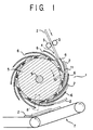
- the delivery fan embodying the principles of this invention is shown receiving signatures 2 as they are fed at high speed from the folding and cutting mechanism, not shown, via a pair of feed rollers 3. After being caught instantaneously by the delivery fan, the signatures 2 are to be successively released therefrom by fixed stripper bars 8. So released, the signatures will fall on an underlying delivery conveyor system 7 in a neatly overlapping series, thereby to be conveyed to a place of shipment.
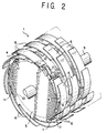
- the delivery fan 1 has a plurality of disklike hubs 5 mounted coaxially on a drive shaft 9 at constant axial spacings.
- the drive shaft 9 is coupled to drive means, not shown, whereby it is rotated in a predetermined direction, clockwise as viewed in FIG. 1, at a speed matching the rate at which the signatures 2 are supplied from the folding and cutting mechanism.
- a plurality of, ten, in the illustrated embodiment, fingers 6 are affixed each at one end to each hub 5 and arcuately extend therefrom both outwardly and upstream, with respect to the predetermined direction of hub rotation, of the hubs.
- Pockets 4 are thus defined by and between the rows of fingers 6. It will be seen that the pockets 4 extend parallel to the axis of the hubs 5, or to the drive shaft 9, and are constantly spaced from one another circumferentially of the hubs. Each pocket 4 is sufficiently wide to receive with appropriate clearance the signatures of the greatest number of pages to be produced by the printing press.
- annular groove 10 is cut in the surface of each hub 5.
- a series of flat springs 11 are mounted in the groove 10 in each hub 5 at the same circumferential spacings as the fingers 6.
- each flat spring 11 is anchored to one hub 5 and extends across one pocket 4 and toward its bottom in order to prevent the signatures 2 from jumping out the pockets.
- each flat spring 11 is preformed to include a fixed end portion 13 screwed at 12 to the hub 5, a midportion 14 extending past the inner, anchored end of one finger toward another finger which is located downstream of the first recited finger with respect to the arrow-marked rotational direction of the delivery fan 1, and a free end portion 15 extending approximately parallel to the second recited finger.
- each flat spring 11 Extending as above from the inner end of the first finger approximately toward the longitudinal midpoint of the second finger, the midportion 14 of each flat spring 11 is angled with respect to the second finger to provide a space wedgeshaped toward the bottom of the pocket between the midportion and the first finger. It will also be noted from FIG. 3 that the free end portion 15 of each flat spring 11 is not held against the second finger but spaced therefrom a spacing t that is slightly less than the known thickness of least page signatures to be produced by the printing press.
- each thin signature 2a will enter one pocket 4 between two circumferentially neighboring rows of fingers 6 of the delivery fan 1 rotating clockwise at a constant speed matching the rate of supply of the signatures.
- the thin signature 2a will travel along the surfaces of the downstream side fingers 6, with respect to the direction of fan rotation, of the pocket. Then the thin signature 2a will enter the wedgeshaped spaces between the midportions 14 of the flat springs 11 and the downstream side fingers 6, thereby to be guided into the narrow spacings t between the free end portions 15 of the flat springs 11 and the downstream side fingers 6. Then the thin signature 2a will arrive at the bottom of the pocket 4 like the lowermost signature of FIG. 3.
- the flat spring free end portions 15 are held spaced from the downstream side fingers 6 for the foregoing reasons, nevertheless the spacing t is made less than the thickness of the least pages signatures to be produced by the press. Therefore, upon engagement of the thin signature 2a between fingers 6 and flat springs 11, these springs will deflect to an extent determined by the thickness of that signature. By reaction, then, the springs will relatively lightly brake the thin, and therefore lightweight, signature, thereby mitigating the impact of the signature hitting the pocket bottom and so preventing the same from rebounding.
- the thick signatures 2b will be admitted into the successive pockets 4 through the same process as are the thin signatures 2a, except for the angle of deflection of the flat springs 11 upon engagement of each such signature between downstream side fingers 6 and flat spring free end portions 15.
- the thick signatures 2b may be much thicker than the spacing t between fingers 6 and flat spring free end portions 15, each such signature by the strengths of its greater mass and kinetic energy will force itself into the spacing t thereby causing the flat springs 11 to deflect through greater angles than in the case of the thin signatures 2a. So deflected, the flat springs 11 will exert correspondingly greater braking forces on the thick signatures 2b and so alleviate the impact of the signatures hitting the pocket bottoms, preventing them from rebounding just as in the case of the thin signatures 2a.
- the signatures 2a or 2b will be successively deposited thereon in an overlapping series by butting against the stripper bars 8 interdigitating with the hubs 5.
- the signatures will be neatly aligned on the conveyor system as they have all been fully bottomed in the fan pockets.
- the flat springs can be of greater rigidity than if, as in the prior art device set forth earlier, they were held against the fingers. Such rigid springs will suffer less permanent strain from cyclic stress and so offer a longer useful life.
Landscapes
- Engineering & Computer Science (AREA)
- Mechanical Engineering (AREA)
- Separation, Sorting, Adjustment, Or Bending Of Sheets To Be Conveyed (AREA)
- Discharge By Other Means (AREA)
Applications Claiming Priority (2)
| Application Number | Priority Date | Filing Date | Title |
|---|---|---|---|
| JP11102017A JP3010557B1 (ja) | 1999-04-09 | 1999-04-09 | 折機の排出用羽根車装置 |
| JP10201799 | 1999-04-09 |
Publications (3)
| Publication Number | Publication Date |
|---|---|
| EP1044913A2 true EP1044913A2 (fr) | 2000-10-18 |
| EP1044913A3 EP1044913A3 (fr) | 2001-09-19 |
| EP1044913B1 EP1044913B1 (fr) | 2004-04-21 |
Family
ID=14315996
Family Applications (1)
| Application Number | Title | Priority Date | Filing Date |
|---|---|---|---|
| EP00105158A Expired - Lifetime EP1044913B1 (fr) | 1999-04-09 | 2000-03-11 | Roue à aubes dans une machine à imprimer rotative pour délivrer des cahiers se chevauchant les uns les autres |
Country Status (4)
| Country | Link |
|---|---|
| US (1) | US6216591B1 (fr) |
| EP (1) | EP1044913B1 (fr) |
| JP (1) | JP3010557B1 (fr) |
| DE (1) | DE60009980T2 (fr) |
Cited By (2)
| Publication number | Priority date | Publication date | Assignee | Title |
|---|---|---|---|---|
| EP2228331A1 (fr) * | 2009-03-10 | 2010-09-15 | Ferag AG | Dispositif et procédé de prise en charge et de traitement d'objets plats flexibles |
| EP2692675A4 (fr) * | 2011-03-30 | 2014-09-10 | Glory Kogyo Kk | Hélice, dispositif pour collecter des feuilles de papier, et procédé pour produire une hélice |
Families Citing this family (9)
| Publication number | Priority date | Publication date | Assignee | Title |
|---|---|---|---|---|
| DE10008136A1 (de) * | 2000-02-22 | 2001-08-23 | Giesecke & Devrient Gmbh | Stapler für blattförmige Gegenstände |
| JP4497657B2 (ja) * | 2000-05-19 | 2010-07-07 | 株式会社ミヤコシ | 枚葉紙の区分けセット出し装置 |
| DE10311858B3 (de) * | 2003-03-17 | 2004-08-19 | Nexpress Solutions Llc | Vorrichtung zum Transport eines im wesentlichen bogenförmigen Elementes, insbesondere eines Bedruckstoffbogens |
| JP4708166B2 (ja) * | 2004-11-25 | 2011-06-22 | オセ−テクノロジーズ・ベー・ヴエー | プリント済みシートのための排出システム |
| JP2008260619A (ja) * | 2007-04-13 | 2008-10-30 | Komori Corp | 羽根車のシート状物減速機構 |
| JP2009062111A (ja) * | 2007-09-04 | 2009-03-26 | Ricoh Co Ltd | シート後処理装置 |
| DE102009047158A1 (de) * | 2009-11-26 | 2011-06-01 | Manroland Ag | Exemplarausleger |
| US10683109B2 (en) * | 2016-08-22 | 2020-06-16 | C.G. Bretting Manufacturing Co., Inc. | System, apparatus and method of placing an insert in a bag |
| US11084680B1 (en) | 2018-04-05 | 2021-08-10 | Imaging Business Machines Llc | Continually running pocket spindle |
Family Cites Families (9)
| Publication number | Priority date | Publication date | Assignee | Title |
|---|---|---|---|---|
| FR1446522A (fr) * | 1965-07-23 | 1966-07-22 | V Leysens & G Meier Ets | Disque rotatif récepteur éjecteur, notamment pour plieuse à feuilles ainsi que lesplieuses pourvues de ce disque ou disque similaire |
| US4052053A (en) * | 1976-01-28 | 1977-10-04 | Fuji Giken Kabushiki Kaisha | Stacker drum of sheet accumulating device |
| US4537390A (en) | 1984-06-14 | 1985-08-27 | Rockwell International Corporation | High speed folder fly |
| DE3760159D1 (en) * | 1986-02-14 | 1989-06-22 | Ferag Ag | Method and apparatus for the insertion of at least one insert into, preferably, folded printed products |
| RU2053184C1 (ru) * | 1990-08-06 | 1996-01-27 | Радуцкий Григорий Аврамович | Устройство для вывода газетной продукции из фальцаппарата рулонной ротационной машины |
| US5359930A (en) * | 1993-09-17 | 1994-11-01 | Rockwell International Corporation | Device for aligning flies for a printing press |
| DE19525168C2 (de) * | 1995-07-11 | 1997-05-28 | Koenig & Bauer Albert Ag | Schaufelrad zum Auslegen von Falzprodukten |
| JPH1121002A (ja) | 1997-07-03 | 1999-01-26 | Toshiba Mach Co Ltd | 輪転印刷機の羽根車装置 |
| DE19804810C2 (de) * | 1998-02-06 | 2003-06-05 | Wifag Maschf | Schaufelrad für eine Druckmaschine |
-
1999
- 1999-04-09 JP JP11102017A patent/JP3010557B1/ja not_active Expired - Fee Related
-
2000
- 2000-03-11 EP EP00105158A patent/EP1044913B1/fr not_active Expired - Lifetime
- 2000-03-11 DE DE60009980T patent/DE60009980T2/de not_active Expired - Fee Related
- 2000-03-14 US US09/524,691 patent/US6216591B1/en not_active Expired - Fee Related
Cited By (4)
| Publication number | Priority date | Publication date | Assignee | Title |
|---|---|---|---|---|
| EP2228331A1 (fr) * | 2009-03-10 | 2010-09-15 | Ferag AG | Dispositif et procédé de prise en charge et de traitement d'objets plats flexibles |
| CH700561A1 (de) * | 2009-03-10 | 2010-09-15 | Ferag Ag | Vorrichtung und verfahren zum übernehmen und weiterverarbeiten von flexiblen, flächigen gegenständen. |
| US8317183B2 (en) | 2009-03-10 | 2012-11-27 | Ferag Ag | Device and process for taking over and further processing of flexible, flat objects |
| EP2692675A4 (fr) * | 2011-03-30 | 2014-09-10 | Glory Kogyo Kk | Hélice, dispositif pour collecter des feuilles de papier, et procédé pour produire une hélice |
Also Published As
| Publication number | Publication date |
|---|---|
| EP1044913B1 (fr) | 2004-04-21 |
| DE60009980T2 (de) | 2005-04-21 |
| JP3010557B1 (ja) | 2000-02-21 |
| JP2000296956A (ja) | 2000-10-24 |
| US6216591B1 (en) | 2001-04-17 |
| DE60009980D1 (de) | 2004-05-27 |
| EP1044913A3 (fr) | 2001-09-19 |
Similar Documents
| Publication | Publication Date | Title |
|---|---|---|
| US6216591B1 (en) | Delivery fan in a rotary printing press for delivering signatures in overlapping succession | |
| US4228997A (en) | Stacking machine | |
| JP5141577B2 (ja) | 紙葉類分離集積機構 | |
| EP2146119B1 (fr) | Dispositif d'étanchéité | |
| JP3731260B2 (ja) | 給紙装置及びそれを備える画像記録機 | |
| US5029842A (en) | Signature handling apparatus | |
| JP3553191B2 (ja) | ファンから印刷物を排出する装置 | |
| US4052053A (en) | Stacker drum of sheet accumulating device | |
| JP2920779B2 (ja) | 印刷物排出装置 | |
| US6145833A (en) | Rotary brush sheet deceleration device | |
| US20010022421A1 (en) | Signature delivery apparatus including two rotating buckets | |
| JP2011006250A (ja) | 媒体集積装置 | |
| JPS6310064B2 (fr) | ||
| US20020074716A1 (en) | Recirculating gripper accumulator having a circular paper path | |
| CN109715539B (zh) | 引导滚轮和包括多个滚轮的输送装置 | |
| EP1304305B1 (fr) | Machine d'insertion pour aligner entre elles des feuilles en mouvement d'une pile, et procédé pour cela dans un assembleur de feuilles | |
| JP4718297B2 (ja) | 紙葉類分離集積装置 | |
| EP1117608B1 (fr) | Machine de separation pour module d'assemblage feuille a feuille | |
| US7931268B2 (en) | Device for braking flat products and corresponding folder | |
| CA2006472C (fr) | Appareil de manutention de documents | |
| US4895359A (en) | Paper sheet counter system | |
| EP1382556B1 (fr) | Dispositif de pliage pour sections de papier imprimé | |
| US5901955A (en) | Gripper seat | |
| US7887035B2 (en) | Fan delivery for a folding apparatus | |
| US3438624A (en) | Separator for folders |
Legal Events
| Date | Code | Title | Description |
|---|---|---|---|
| PUAI | Public reference made under article 153(3) epc to a published international application that has entered the european phase |
Free format text: ORIGINAL CODE: 0009012 |
|
| 17P | Request for examination filed |
Effective date: 20000311 |
|
| AK | Designated contracting states |
Kind code of ref document: A2 Designated state(s): AT BE CH CY DE DK ES FI FR GB GR IE IT LI LU MC NL PT SE Kind code of ref document: A2 Designated state(s): CH DE FR GB LI |
|
| AX | Request for extension of the european patent |
Free format text: AL;LT;LV;MK;RO;SI |
|
| PUAL | Search report despatched |
Free format text: ORIGINAL CODE: 0009013 |
|
| AK | Designated contracting states |
Kind code of ref document: A3 Designated state(s): AT BE CH CY DE DK ES FI FR GB GR IE IT LI LU MC NL PT SE |
|
| AX | Request for extension of the european patent |
Free format text: AL;LT;LV;MK;RO;SI |
|
| AKX | Designation fees paid |
Free format text: CH DE FR GB LI |
|
| 17Q | First examination report despatched |
Effective date: 20030227 |
|
| GRAP | Despatch of communication of intention to grant a patent |
Free format text: ORIGINAL CODE: EPIDOSNIGR1 |
|
| GRAS | Grant fee paid |
Free format text: ORIGINAL CODE: EPIDOSNIGR3 |
|
| GRAA | (expected) grant |
Free format text: ORIGINAL CODE: 0009210 |
|
| AK | Designated contracting states |
Kind code of ref document: B1 Designated state(s): CH DE FR GB LI |
|
| PG25 | Lapsed in a contracting state [announced via postgrant information from national office to epo] |
Ref country code: FR Free format text: LAPSE BECAUSE OF FAILURE TO SUBMIT A TRANSLATION OF THE DESCRIPTION OR TO PAY THE FEE WITHIN THE PRESCRIBED TIME-LIMIT Effective date: 20040421 Ref country code: CH Free format text: LAPSE BECAUSE OF FAILURE TO SUBMIT A TRANSLATION OF THE DESCRIPTION OR TO PAY THE FEE WITHIN THE PRESCRIBED TIME-LIMIT Effective date: 20040421 Ref country code: LI Free format text: LAPSE BECAUSE OF FAILURE TO SUBMIT A TRANSLATION OF THE DESCRIPTION OR TO PAY THE FEE WITHIN THE PRESCRIBED TIME-LIMIT Effective date: 20040421 |
|
| REG | Reference to a national code |
Ref country code: GB Ref legal event code: FG4D |
|
| REG | Reference to a national code |
Ref country code: CH Ref legal event code: EP |
|
| REF | Corresponds to: |
Ref document number: 60009980 Country of ref document: DE Date of ref document: 20040527 Kind code of ref document: P |
|
| REG | Reference to a national code |
Ref country code: CH Ref legal event code: PL |
|
| PLBE | No opposition filed within time limit |
Free format text: ORIGINAL CODE: 0009261 |
|
| STAA | Information on the status of an ep patent application or granted ep patent |
Free format text: STATUS: NO OPPOSITION FILED WITHIN TIME LIMIT |
|
| EN | Fr: translation not filed | ||
| 26N | No opposition filed |
Effective date: 20050124 |
|
| PGFP | Annual fee paid to national office [announced via postgrant information from national office to epo] |
Ref country code: GB Payment date: 20070119 Year of fee payment: 8 |
|
| GBPC | Gb: european patent ceased through non-payment of renewal fee |
Effective date: 20080311 |
|
| PG25 | Lapsed in a contracting state [announced via postgrant information from national office to epo] |
Ref country code: GB Free format text: LAPSE BECAUSE OF NON-PAYMENT OF DUE FEES Effective date: 20080311 |
|
| PGFP | Annual fee paid to national office [announced via postgrant information from national office to epo] |
Ref country code: DE Payment date: 20090115 Year of fee payment: 10 |
|
| PG25 | Lapsed in a contracting state [announced via postgrant information from national office to epo] |
Ref country code: DE Free format text: LAPSE BECAUSE OF NON-PAYMENT OF DUE FEES Effective date: 20101001 |