EP1044918B1 - Dispositif d'emmagasinage d'un élément allongé flexible - Google Patents
Dispositif d'emmagasinage d'un élément allongé flexible Download PDFInfo
- Publication number
- EP1044918B1 EP1044918B1 EP00107428A EP00107428A EP1044918B1 EP 1044918 B1 EP1044918 B1 EP 1044918B1 EP 00107428 A EP00107428 A EP 00107428A EP 00107428 A EP00107428 A EP 00107428A EP 1044918 B1 EP1044918 B1 EP 1044918B1
- Authority
- EP
- European Patent Office
- Prior art keywords
- axle
- bearing elements
- bearing
- elements
- section
- Prior art date
- Legal status (The legal status is an assumption and is not a legal conclusion. Google has not performed a legal analysis and makes no representation as to the accuracy of the status listed.)
- Expired - Lifetime
Links
- 239000002184 metal Substances 0.000 claims description 4
- 239000000463 material Substances 0.000 claims description 2
- 238000013016 damping Methods 0.000 claims 1
- 239000003365 glass fiber Substances 0.000 description 5
- 238000004804 winding Methods 0.000 description 5
- 238000010276 construction Methods 0.000 description 2
- 230000006378 damage Effects 0.000 description 2
- 239000000853 adhesive Substances 0.000 description 1
- 230000001070 adhesive effect Effects 0.000 description 1
- 239000004568 cement Substances 0.000 description 1
- 239000004927 clay Substances 0.000 description 1
- 238000000034 method Methods 0.000 description 1
- 210000000056 organ Anatomy 0.000 description 1
- 230000000149 penetrating effect Effects 0.000 description 1
- 238000005096 rolling process Methods 0.000 description 1
- 239000002351 wastewater Substances 0.000 description 1
Images


Classifications
-
- B—PERFORMING OPERATIONS; TRANSPORTING
- B65—CONVEYING; PACKING; STORING; HANDLING THIN OR FILAMENTARY MATERIAL
- B65H—HANDLING THIN OR FILAMENTARY MATERIAL, e.g. SHEETS, WEBS, CABLES
- B65H75/00—Storing webs, tapes, or filamentary material, e.g. on reels
- B65H75/02—Cores, formers, supports, or holders for coiled, wound, or folded material, e.g. reels, spindles, bobbins, cop tubes, cans, mandrels or chucks
- B65H75/34—Cores, formers, supports, or holders for coiled, wound, or folded material, e.g. reels, spindles, bobbins, cop tubes, cans, mandrels or chucks specially adapted or mounted for storing and repeatedly paying-out and re-storing lengths of material provided for particular purposes, e.g. anchored hoses, power cables
- B65H75/36—Cores, formers, supports, or holders for coiled, wound, or folded material, e.g. reels, spindles, bobbins, cop tubes, cans, mandrels or chucks specially adapted or mounted for storing and repeatedly paying-out and re-storing lengths of material provided for particular purposes, e.g. anchored hoses, power cables without essentially involving the use of a core or former internal to a stored package of material, e.g. with stored material housed within casing or container, or intermittently engaging a plurality of supports as in sinuous or serpentine fashion
- B65H75/362—Cores, formers, supports, or holders for coiled, wound, or folded material, e.g. reels, spindles, bobbins, cop tubes, cans, mandrels or chucks specially adapted or mounted for storing and repeatedly paying-out and re-storing lengths of material provided for particular purposes, e.g. anchored hoses, power cables without essentially involving the use of a core or former internal to a stored package of material, e.g. with stored material housed within casing or container, or intermittently engaging a plurality of supports as in sinuous or serpentine fashion with stored material housed within a casing or container
- B65H75/364—Cores, formers, supports, or holders for coiled, wound, or folded material, e.g. reels, spindles, bobbins, cop tubes, cans, mandrels or chucks specially adapted or mounted for storing and repeatedly paying-out and re-storing lengths of material provided for particular purposes, e.g. anchored hoses, power cables without essentially involving the use of a core or former internal to a stored package of material, e.g. with stored material housed within casing or container, or intermittently engaging a plurality of supports as in sinuous or serpentine fashion with stored material housed within a casing or container the stored material being coiled
Definitions
- the invention relates to a device for receiving windable or storable Elements such as traction means for pulling cables into empty conduits, Cables, hoses or the like, with a storage device, for example a storage drum, which is arranged in a storage rack, wherein the storage rack has an axis with at least one bearing on which the storage device is rotatably mounted.
- a storage device for example a storage drum, which is arranged in a storage rack, wherein the storage rack has an axis with at least one bearing on which the storage device is rotatably mounted.
- tubes are e.g. from shaped stones, Clay pipes, cement pipes or the like when used to drain Waste water, or from cable protection pipes, in which power cables or telephone cables are pulled in.
- pull-in devices for example from DE 36 36 943 C2 known, which have a reel wheel, in which a flexible, strand-shaped Feeding element, for example a glass fiber rod can be wound up, one end attached to the reel wheel and the other end is guided to the outside by a guide.
- the reel wheel has an axis on which is rotatably mounted in a stand.
- the strand-shaped pull-in member is in terms of its tensile strength on the shut off cables to be pulled in or the like, i.e. they are collection organs with different diameters and in particular different Lengths known, which depend on the length of the draw-in distance and associated frictional resistance must be selected. As a result it is necessary to keep several such pull-in devices available, if different Cables or the like are to be handled.
- a further pull-in device which consists of a Winding device with a loosely rotatable wheel for winding a Glass fiber rod exists.
- the winding device has a frame, in which the wheel is mounted by means of a horizontal axis.
- the frame has two lateral, approximately triangular stands and a U-shaped protruding vertically upward from the region of the axis Hanger.
- the wheel is supported on two axle bearings that are spaced apart are arranged to each other on the axis.
- the invention has for its object to further develop a generic device such that the above-described disadvantageous properties are avoided and that the device can be used variably and easily adapted to certain operating conditions and in particular can be quickly converted.
- the bearing consists of two bearing elements which are tubular section-shaped, have a bore and have a cone at one end, that the storage device has a pipe section receiving the axis, the opening of which widens conically at both ends, that the cone of the bearing elements is designed corresponding to the conical ends of the opening of the tube section and that the axis has at least one particularly removable clamping element with which the bearing elements can be moved and braced relative to the tube section.
- the division of the Bearing provided in two bearing elements that are aligned with the axis of the storage device each with a cone and flared openings cooperate, the surface tension between the two cones and the flared ends of the opening through the tension member can be varied so that the frictional force between the clamping element the storage elements and the storage device for setting the Rotational speed is possible.
- the possible Rotation speed depending on the wound element, in particular Traction means for pulling cables through the tensioning element varies depending on the coiled or stored Mass of the traction device with respect to one caused by the inertia Running after the storage device to take into account.
- the removable clamping element also offers the possibility in a storage rack different storage devices in the same Way to store.
- storage devices with, for example different diameter and thus capacity in the Storage rack can be arranged interchangeably, depending on the Storage device a permissible speed of rotation via the clamping elements is adjustable.
- the bearing elements made of a tough plastic and the pipe section made of metal is trained. This has the advantage that the bearing elements, the possibly subject to wear, in a simpler and cheaper way Made in this way and, if necessary, after reaching a certain wear can be replaced without expensive work on Bearings are necessary. Since the bearing elements made of tough hard plastic Wear less than the pipe section made of metal kept very low in the area of the pipe section, so that the Storage device with the pipe section a durable construction element is subjected to a very frequent exchange in the storage rack can be, without serious handling restrictions occur.
- the bearing elements can be positively fixed in such a way that they are rotationally fixed are arranged to the axis.
- the bearing elements preferably have at its end opposite the cone, one is semicircular in cross section or prism-shaped recess whose longitudinal axis runs perpendicular to the longitudinal axis of the bore, so that the bearing elements for example, encompass a section of the storage rack in a form-fitting manner can to prevent rotation of the bearing elements around the axis.
- the axis at least at one end Has threaded section, and that the clamping element as a nut or Knurled wheel is formed, which or which on the threaded portion can be screwed on and clamped against the bearing elements.
- This configuration has the advantage that the frictional force between the bearing elements and the pipe section in a simple manner by tightening or loosening the Nut or the knurled wheel is possible.
- these enable Construction elements a quick opening of the warehouse, so that the change a storage device in a short time and without special tools is.
- bearing elements are subject to wear and tear, Expansion of the bearing elements should also be possible for laypersons, that the two bearing elements are identical, so that they are as inexpensive spare parts can be offered and stocked. About that In addition, there is the advantage that the mounting and dismounting of the bearing elements is simplified because it is without extensive knowledge for everyone is possible.
- the handling of the device according to the invention with regard to its variability and their adaptability to certain operating conditions, in particular their upgradeability is further improved in that the Axle is mounted with one end in the storage rack, so that the axis as Stub axle is formed, which allows the bearing to open quickly and thus a quick exchange of the storage components or the storage device allows.
- the clamping element is released, a bearing element subtracted from the axis, so that then the storage element can be removed from the storage rack in such a way that it is withdrawn from the axis can be.
- the axis at least at one end a polygonal, in particular rectangular Has cross-section on which a holder can be placed, the one corresponding Has opening and the bearing element relative to the axis positive sets.
- the holder is preferably in the form of a tape guide with or without a length measuring device educated. This configuration has the advantage that in constructive simply set the two bearing elements relative to the axis can be, so that a driving force only in the area of the two cones and the two conically widening ends of the opening of the pipe section occurs.
- Figures 1 to 4 is a device for receiving a traction device shown for pulling cables into empty conduits.
- a traction device Glass fiber rod 1 use, which is designed in a storage drum
- Storage device 2 is arranged such that it has a defined The outlet is pulled out of the storage device 2 and pushed into it can be.
- the storage device 2 becomes corresponding the conveying direction of the glass fiber rod 1 rotated about an axis 3, which connects the storage device 2 to a storage rack 4.
- the storage device 2 has an essentially U-shaped cross section trained cage 5 on the spokes with a pipe section 7 is connected.
- Pipe section 7, spokes 6 and cage 5 are made of metal and are welded together.
- pipe section 7, spokes 6 and cage 5 also made of a different material, in particular be made of tough plastic, of course also other connecting elements for connecting these components can be provided. Screw connections should be mentioned here, Rivet connections and adhesive connections.
- the storage rack 4 consists of two pivotally connected Tubes 8 and 9 which are bent such that they have two free ends, which run parallel to each other, one end of each as a riot element with a correspondingly large length and one end each as a connecting element between the tubes 8 and 9 with a correspondingly short Length is formed.
- Figures 8 and 9 is a portion of the storage rack 4 shown in detail, which is described in more detail below becomes.
- FIG. 6 is the structure of the storage of the storage device 2 on the storage rack 4 as follows:
- the axis 3 is designed as a stub axle and with one end on the storage rack 4 welded. For this purpose, the axis 3 passes through a section of the Tube 9 perpendicular to the longitudinal extent of this tube 9.
- the axis 3 passes through an opening 11 of the pipe section 7, the Diameter is larger than the diameter of the axis 3.
- the opening 11. has two conically widening ends 12. In the conically widening Ends 12 engage two bearing elements in the form of tubular sections 13 each with a cone 14, the conically widening Ends 12 of the opening 11 corresponding to the conical ends 14 the bearing elements 13 are formed.
- the bearing elements 13 made of a tough, hard plastic have a bore 15, the diameter of which corresponds to the diameter of the axis 3 equivalent. As a result, the axis 3 passes through the two bearing elements 13, which are spaced apart with the interposition of the pipe section 7 are.
- the bearing elements 13 have the cone 14 opposite them End a recess 16 formed semicircular in cross section, the Longitudinal axis is perpendicular to the longitudinal axis of the bore 15.
- This Recess 16 is in the area corresponding to the outer curvature of the tube 9 the penetrating axis 3, so that the bearing element 13th with the recess 16 partially encompasses the tube 9 of the storage rack 4.
- the axis 3 is cylindrical over almost its entire length. Only in the area of their end 17 and its end facing the storage rack 4, the axis 3 has a square Cross section on. The axis has in the area of the opposite end 3 an external thread 18 on which a clamping element 19 in the form of a Knurled wheel can be screwed on. About the clamping element 19, the press tension of the bearing elements 13 in the region of the conical ends 12 of the Pipe section 7 can be changed to a greater or lesser friction force, which the possible rotational speed of the storage device 2 determines to discontinue.
- both bearing elements 13 are rotatably opposite the axis 3 are arranged so that a storage of the pipe section 7 takes place only in the area of the two cones 14.
- this is a bearing element 13 through which the tube 9 of the storage rack 4 encompassing recess 16 is rotatably arranged to the axis 3.
- the second bearing element 13 facing the clamping element 19 is identical formed with the bearing element 4 facing the bearing frame 4.
- a Holder 20 is provided, which engages in the recess 16 outer contour and has an opening 21 whose shape matches the outer contour of the End 17 of the axis 3 coincides, so that the holder 20, the end 17 of the Grips around axis 3.
- the holder 20 is designed as a tape guide and serves to guide the glass fiber rod 1 after leaving it the storage device 2.
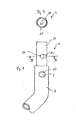
- Figure 8 shows a portion of the tube 8 of the storage rack 4.
- one end of the tube 8 has a bore 23 through which the Axis 3 engages.
- the axis 3 with the tube 8 is in the region of the bore 23 of the storage rack 4 positively connected, namely welded.
- the Tube 8 also has a stepped section 24 at its free end whose outer diameter corresponds to the inner diameter of the tube 9 matches, so that the tube 9 can be pushed over the section 24 and around this section 24 is pivotable.
- the section 24 has two elongated holes arranged diametrically opposite one another 25, which passes through a bolt 26, the form-fitting with the tube 9 is connected.
- the elongated holes 25 and the bolt 26 limit the mobility of the tube 29 relative to the section 24, so that the in FIG. 4th Relative position of the two tubes 8 and 9 shown with respect to one another of the angle set between the tubes 8 and 9 is limited.
Landscapes
- Storing, Repeated Paying-Out, And Re-Storing Of Elongated Articles (AREA)
- Printers Characterized By Their Purpose (AREA)
- Arrangements For Transmission Of Measured Signals (AREA)
- Apparatus For Radiation Diagnosis (AREA)
- Radar Systems Or Details Thereof (AREA)
- Storage Of Web-Like Or Filamentary Materials (AREA)
Claims (9)
- Dispositif pour loger des éléments pouvant être enroulés ou stockés (1) tels que des moyens de traction pour tirer des câbles dans des gaines vides, des câbles, des tuyaux flexibles ou équivalent, avec un dispositif de stockage (2), par exemple un tambour de stockage qui est placé dans un support de stockage (4), le support de stockage présentant un axe (3) avec au moins un palier sur lequel le dispositif de stockage est positionné rotatif,
caractérisé en ce que le palier est constitué par deux éléments de palier (13) qui sont configurés en forme de section de tuyau, qui présentent une forure (15) et à une extrémité un cône (14),
que le dispositif de stockage (2) a une section de tuyau (7) qui reçoit l'axe (3), section dont l'ouverture (11) s'élargit en cône aux deux extrémités,
que le cône (14) des éléments de palier (13) est configuré en correspondant aux extrémités coniques (12) de l'ouverture (11) de la section de tuyau (7) et
que l'axe (3) présente au moins un élément de serrage en particulier démontable avec lequel les éléments de palier (13) peuvent être déplacés par rapport à la section de tuyau (7) et serrés. - Dispositif selon la revendication 1,
caractérisé en ce que les éléments de palier (13) sont en une matière plastique tenace dure et la section de tuyau (7) est configurée en métal. - Dispositif selon la revendication 1,
caractérisé en ce que les éléments de palier (13) peuvent être fixés de manière crabotée de telle manière qu'ils sont placés résistants à la rotation par rapport à l'axe (3). - Dispositif selon la revendication 3,
caractérisé en ce que les éléments de palier (13) présentent à leurs extrémités opposées au cône (14) un creux (16) configuré de section en forme de demi-cercle ou de prisme dont l'axe longitudinal est à angle droit par rapport à l'axe longitudinal de la forure (15). - Dispositif selon la revendication 1,
caractérisé en ce que l'axe (3) présente une section filetée (18) à au moins une extrémité (17) et que l'élément de serrage (19) est configuré comme un écrou ou une molette qui peut être vissé(e) sur la section filetée (18) et qui peut être serré(e) contre les éléments de palier (13). - Dispositif selon la revendication 1,
caractérisé en ce que les deux éléments de palier (13) sont configurés identiques. - Dispositif selon la revendication 1,
caractérisé en ce que l'axe (3) est positionné avec une extrémité dans le support de stockage (4). - Dispositif selon la revendication 1,
caractérisé en ce que l'axe (3) présente au moins à une extrémité (17) une section polygonale, en particulier rectangulaire, sur laquelle un support (20) peut être posé qui a une ouverture correspondante (21) et qui fixe l'élément de stockage (13) de manière crabotée par rapport à l'axe (3). - Dispositif selon la revendication 8,
caractérisé en ce que le support (20) est configuré comme guide de bande avec ou sans appareil métreur.
Applications Claiming Priority (4)
| Application Number | Priority Date | Filing Date | Title |
|---|---|---|---|
| DE19917183 | 1999-04-16 | ||
| DE19917183 | 1999-04-16 | ||
| DE19919005 | 1999-04-27 | ||
| DE19919005A DE19919005C2 (de) | 1999-04-16 | 1999-04-27 | Vorrichtung zur Aufnahme von wickel- oder speicherbaren Elementen |
Publications (3)
| Publication Number | Publication Date |
|---|---|
| EP1044918A2 EP1044918A2 (fr) | 2000-10-18 |
| EP1044918A3 EP1044918A3 (fr) | 2001-04-18 |
| EP1044918B1 true EP1044918B1 (fr) | 2003-07-30 |
Family
ID=26052933
Family Applications (1)
| Application Number | Title | Priority Date | Filing Date |
|---|---|---|---|
| EP00107428A Expired - Lifetime EP1044918B1 (fr) | 1999-04-16 | 2000-04-06 | Dispositif d'emmagasinage d'un élément allongé flexible |
Country Status (5)
| Country | Link |
|---|---|
| EP (1) | EP1044918B1 (fr) |
| AT (1) | ATE246141T1 (fr) |
| DK (1) | DK1044918T3 (fr) |
| ES (1) | ES2211406T3 (fr) |
| PT (1) | PT1044918E (fr) |
Families Citing this family (1)
| Publication number | Priority date | Publication date | Assignee | Title |
|---|---|---|---|---|
| DE102018122065A1 (de) * | 2018-09-11 | 2020-03-12 | HEDI GmbH Elektro- und Gerätebau | Kabeltrommel mit schräg gestellter Trommelachse |
Family Cites Families (6)
| Publication number | Priority date | Publication date | Assignee | Title |
|---|---|---|---|---|
| DE6910759U (de) * | 1969-03-17 | 1969-08-21 | Hans Alfred Hagist | Kabelrolle |
| DE2333435A1 (de) * | 1973-06-30 | 1975-01-16 | Werner Cielker | Einziehgeraet |
| GB8505866D0 (en) * | 1985-03-07 | 1985-04-11 | Pearpoint Ltd | Semi-rigid rods |
| DE3636943A1 (de) * | 1986-10-30 | 1988-05-11 | Katimex Cielker Gmbh | Einziehgeraet |
| DE4429372A1 (de) * | 1994-08-22 | 1996-02-29 | C N T Contactnormtechnik | Transportvorrichtung |
| JPH09278282A (ja) * | 1996-04-16 | 1997-10-28 | Mirai Ind Co Ltd | 長尺材の繰出し装置 |
-
2000
- 2000-04-06 PT PT00107428T patent/PT1044918E/pt unknown
- 2000-04-06 EP EP00107428A patent/EP1044918B1/fr not_active Expired - Lifetime
- 2000-04-06 AT AT00107428T patent/ATE246141T1/de active
- 2000-04-06 DK DK00107428T patent/DK1044918T3/da active
- 2000-04-06 ES ES00107428T patent/ES2211406T3/es not_active Expired - Lifetime
Also Published As
| Publication number | Publication date |
|---|---|
| ATE246141T1 (de) | 2003-08-15 |
| DK1044918T3 (da) | 2003-11-17 |
| ES2211406T3 (es) | 2004-07-16 |
| EP1044918A2 (fr) | 2000-10-18 |
| PT1044918E (pt) | 2003-12-31 |
| EP1044918A3 (fr) | 2001-04-18 |
Similar Documents
| Publication | Publication Date | Title |
|---|---|---|
| DE2741016B2 (fr) | ||
| DE102019129966B3 (de) | Vorrichtung und Verfahren zum Aufwickeln eines Fadens | |
| DE3636943A1 (de) | Einziehgeraet | |
| EP1318741B1 (fr) | Tringle a rideaux | |
| EP4046925A2 (fr) | Dispositif de maintien et d'enlèvement d'une feuille | |
| DE19919005C2 (de) | Vorrichtung zur Aufnahme von wickel- oder speicherbaren Elementen | |
| EP1044918A2 (fr) | Dispositif d'emmagasinage d'un élément allongé flexible | |
| CH680776A5 (en) | Cutting and opening up underground pipes - using tool with cable winch to pull cutter cone through old pipeline | |
| DE3201138C2 (de) | Verriegelungsvorrichtung zur axialen Festlegung von nicht drehbaren Spulen eines Drahtablaufgerätes mit horizontalen feststehenden Achsen | |
| CH678421A5 (fr) | ||
| DE102016224176B3 (de) | Vorrichtung und Verfahren zum Abwickeln eines Materials von einer Vorratstrommel | |
| EP3505455B1 (fr) | Enrouleur | |
| EP0087500B1 (fr) | Dispositif de déplacement pour un tuyau de chauffage du sol | |
| DE19610891C1 (de) | Vorrichtung zum Aufwickeln faden- und bandförmigen Gutes | |
| DE102024102180B3 (de) | Vorrichtung für den Auf- und Abbau eines Zauns | |
| DE4202310A1 (de) | Vorrichtung zum einziehen eines kabels | |
| DE4344218A1 (de) | Abwickelvorrichtung für Wickelgut, insbesondere für Elektro- und Glasfaserkabel | |
| DE9112515U1 (de) | Vorrichtung zum Speichern von strangförmigem Material | |
| DE102008036351B4 (de) | Gurtaufwickler | |
| DE1815343A1 (de) | Aufhaenger fuer Rohre od.dgl. | |
| DE10245830A1 (de) | Vorrichtung zum Zuschneiden von Dämmmaterial | |
| DE202022104966U1 (de) | Wickelvorrichtung für einen Schlauch, ein Kabel, ein Seil oder ein ähnlich aufzuwickelendes Element | |
| DE4024185A1 (de) | Vorrichtung zum fuehren von langgestreckten flexiblen gegenstaenden, insbesondere draehten, schnueren, litzen oder dergleichen | |
| DE10012486A1 (de) | Kabeltrommel | |
| DE10361757B3 (de) | Vorrichtung zum Abwickeln eines Drahtes von einem Drahtspanner |
Legal Events
| Date | Code | Title | Description |
|---|---|---|---|
| PUAI | Public reference made under article 153(3) epc to a published international application that has entered the european phase |
Free format text: ORIGINAL CODE: 0009012 |
|
| AK | Designated contracting states |
Kind code of ref document: A2 Designated state(s): AT BE CH CY DE DK ES FI FR GB GR IE IT LI LU MC NL PT SE |
|
| AX | Request for extension of the european patent |
Free format text: AL;LT;LV;MK;RO;SI |
|
| PUAL | Search report despatched |
Free format text: ORIGINAL CODE: 0009013 |
|
| AK | Designated contracting states |
Kind code of ref document: A3 Designated state(s): AT BE CH CY DE DK ES FI FR GB GR IE IT LI LU MC NL PT SE |
|
| AX | Request for extension of the european patent |
Free format text: AL;LT;LV;MK;RO;SI |
|
| RIC1 | Information provided on ipc code assigned before grant |
Free format text: 7B 65H 75/36 A, 7B 65H 75/44 B |
|
| 17P | Request for examination filed |
Effective date: 20010911 |
|
| AKX | Designation fees paid |
Free format text: AT BE CH CY DE DK ES FI FR GB GR IE IT LI LU MC NL PT SE |
|
| GRAH | Despatch of communication of intention to grant a patent |
Free format text: ORIGINAL CODE: EPIDOS IGRA |
|
| GRAH | Despatch of communication of intention to grant a patent |
Free format text: ORIGINAL CODE: EPIDOS IGRA |
|
| GRAA | (expected) grant |
Free format text: ORIGINAL CODE: 0009210 |
|
| AK | Designated contracting states |
Designated state(s): AT BE CH CY DE DK ES FI FR GB GR IE IT LI LU MC NL PT SE |
|
| PG25 | Lapsed in a contracting state [announced via postgrant information from national office to epo] |
Ref country code: CY Free format text: LAPSE BECAUSE OF FAILURE TO SUBMIT A TRANSLATION OF THE DESCRIPTION OR TO PAY THE FEE WITHIN THE PRESCRIBED TIME-LIMIT Effective date: 20030730 |
|
| REG | Reference to a national code |
Ref country code: GB Ref legal event code: FG4D Free format text: NOT ENGLISH |
|
| REG | Reference to a national code |
Ref country code: CH Ref legal event code: EP |
|
| REG | Reference to a national code |
Ref country code: IE Ref legal event code: FG4D Free format text: GERMAN |
|
| REF | Corresponds to: |
Ref document number: 50003061 Country of ref document: DE Date of ref document: 20030904 Kind code of ref document: P |
|
| REG | Reference to a national code |
Ref country code: CH Ref legal event code: NV Representative=s name: HEPP, WENGER & RYFFEL AG |
|
| REG | Reference to a national code |
Ref country code: GR Ref legal event code: EP Ref document number: 20030404381 Country of ref document: GR Ref country code: DK Ref legal event code: T3 |
|
| REG | Reference to a national code |
Ref country code: SE Ref legal event code: TRGR |
|
| GBT | Gb: translation of ep patent filed (gb section 77(6)(a)/1977) |
Effective date: 20031023 |
|
| PG25 | Lapsed in a contracting state [announced via postgrant information from national office to epo] |
Ref country code: MC Free format text: LAPSE BECAUSE OF NON-PAYMENT OF DUE FEES Effective date: 20040430 |
|
| ET | Fr: translation filed | ||
| PLBE | No opposition filed within time limit |
Free format text: ORIGINAL CODE: 0009261 |
|
| STAA | Information on the status of an ep patent application or granted ep patent |
Free format text: STATUS: NO OPPOSITION FILED WITHIN TIME LIMIT |
|
| REG | Reference to a national code |
Ref country code: ES Ref legal event code: FG2A Ref document number: 2211406 Country of ref document: ES Kind code of ref document: T3 |
|
| 26N | No opposition filed |
Effective date: 20040504 |
|
| PGFP | Annual fee paid to national office [announced via postgrant information from national office to epo] |
Ref country code: IE Payment date: 20060426 Year of fee payment: 7 |
|
| REG | Reference to a national code |
Ref country code: IE Ref legal event code: MM4A |
|
| PG25 | Lapsed in a contracting state [announced via postgrant information from national office to epo] |
Ref country code: IE Free format text: LAPSE BECAUSE OF NON-PAYMENT OF DUE FEES Effective date: 20070406 |
|
| PGFP | Annual fee paid to national office [announced via postgrant information from national office to epo] |
Ref country code: GR Payment date: 20120425 Year of fee payment: 13 |
|
| PGFP | Annual fee paid to national office [announced via postgrant information from national office to epo] |
Ref country code: ES Payment date: 20120425 Year of fee payment: 13 |
|
| PGFP | Annual fee paid to national office [announced via postgrant information from national office to epo] |
Ref country code: PT Payment date: 20120403 Year of fee payment: 13 |
|
| PGFP | Annual fee paid to national office [announced via postgrant information from national office to epo] |
Ref country code: AT Payment date: 20120411 Year of fee payment: 13 |
|
| PGFP | Annual fee paid to national office [announced via postgrant information from national office to epo] |
Ref country code: LU Payment date: 20130419 Year of fee payment: 14 |
|
| PGFP | Annual fee paid to national office [announced via postgrant information from national office to epo] |
Ref country code: SE Payment date: 20130418 Year of fee payment: 14 Ref country code: BE Payment date: 20130418 Year of fee payment: 14 Ref country code: DK Payment date: 20130418 Year of fee payment: 14 Ref country code: DE Payment date: 20130627 Year of fee payment: 14 Ref country code: GB Payment date: 20130418 Year of fee payment: 14 Ref country code: CH Payment date: 20130422 Year of fee payment: 14 |
|
| PGFP | Annual fee paid to national office [announced via postgrant information from national office to epo] |
Ref country code: NL Payment date: 20130418 Year of fee payment: 14 Ref country code: IT Payment date: 20130424 Year of fee payment: 14 Ref country code: FR Payment date: 20130515 Year of fee payment: 14 Ref country code: FI Payment date: 20130411 Year of fee payment: 14 |
|
| REG | Reference to a national code |
Ref country code: PT Ref legal event code: MM4A Free format text: LAPSE DUE TO NON-PAYMENT OF FEES Effective date: 20131007 |
|
| REG | Reference to a national code |
Ref country code: GR Ref legal event code: ML Ref document number: 20030404381 Country of ref document: GR Effective date: 20131104 |
|
| PG25 | Lapsed in a contracting state [announced via postgrant information from national office to epo] |
Ref country code: PT Free format text: LAPSE BECAUSE OF NON-PAYMENT OF DUE FEES Effective date: 20131007 |
|
| PG25 | Lapsed in a contracting state [announced via postgrant information from national office to epo] |
Ref country code: GR Free format text: LAPSE BECAUSE OF NON-PAYMENT OF DUE FEES Effective date: 20131104 |
|
| REG | Reference to a national code |
Ref country code: DE Ref legal event code: R119 Ref document number: 50003061 Country of ref document: DE |
|
| REG | Reference to a national code |
Ref country code: DK Ref legal event code: EBP Effective date: 20140430 |
|
| REG | Reference to a national code |
Ref country code: NL Ref legal event code: V1 Effective date: 20141101 |
|
| PG25 | Lapsed in a contracting state [announced via postgrant information from national office to epo] |
Ref country code: LU Free format text: LAPSE BECAUSE OF NON-PAYMENT OF DUE FEES Effective date: 20140406 |
|
| REG | Reference to a national code |
Ref country code: CH Ref legal event code: PL |
|
| REG | Reference to a national code |
Ref country code: SE Ref legal event code: EUG |
|
| REG | Reference to a national code |
Ref country code: AT Ref legal event code: MM01 Ref document number: 246141 Country of ref document: AT Kind code of ref document: T Effective date: 20140406 |
|
| GBPC | Gb: european patent ceased through non-payment of renewal fee |
Effective date: 20140406 |
|
| REG | Reference to a national code |
Ref country code: DE Ref legal event code: R119 Ref document number: 50003061 Country of ref document: DE Effective date: 20141101 |
|
| REG | Reference to a national code |
Ref country code: FR Ref legal event code: ST Effective date: 20141231 |
|
| PG25 | Lapsed in a contracting state [announced via postgrant information from national office to epo] |
Ref country code: CH Free format text: LAPSE BECAUSE OF NON-PAYMENT OF DUE FEES Effective date: 20140430 Ref country code: SE Free format text: LAPSE BECAUSE OF NON-PAYMENT OF DUE FEES Effective date: 20140407 Ref country code: DE Free format text: LAPSE BECAUSE OF NON-PAYMENT OF DUE FEES Effective date: 20141101 Ref country code: LI Free format text: LAPSE BECAUSE OF NON-PAYMENT OF DUE FEES Effective date: 20140430 Ref country code: GB Free format text: LAPSE BECAUSE OF NON-PAYMENT OF DUE FEES Effective date: 20140406 Ref country code: FI Free format text: LAPSE BECAUSE OF NON-PAYMENT OF DUE FEES Effective date: 20140406 |
|
| PG25 | Lapsed in a contracting state [announced via postgrant information from national office to epo] |
Ref country code: NL Free format text: LAPSE BECAUSE OF NON-PAYMENT OF DUE FEES Effective date: 20141101 Ref country code: AT Free format text: LAPSE BECAUSE OF NON-PAYMENT OF DUE FEES Effective date: 20140406 Ref country code: FR Free format text: LAPSE BECAUSE OF NON-PAYMENT OF DUE FEES Effective date: 20140430 |
|
| PG25 | Lapsed in a contracting state [announced via postgrant information from national office to epo] |
Ref country code: IT Free format text: LAPSE BECAUSE OF NON-PAYMENT OF DUE FEES Effective date: 20140406 |
|
| PG25 | Lapsed in a contracting state [announced via postgrant information from national office to epo] |
Ref country code: DK Free format text: LAPSE BECAUSE OF NON-PAYMENT OF DUE FEES Effective date: 20140430 |
|
| REG | Reference to a national code |
Ref country code: ES Ref legal event code: FD2A Effective date: 20150528 |
|
| PG25 | Lapsed in a contracting state [announced via postgrant information from national office to epo] |
Ref country code: ES Free format text: LAPSE BECAUSE OF NON-PAYMENT OF DUE FEES Effective date: 20140407 |
|
| PG25 | Lapsed in a contracting state [announced via postgrant information from national office to epo] |
Ref country code: BE Free format text: LAPSE BECAUSE OF NON-PAYMENT OF DUE FEES Effective date: 20140430 |