EP1045076B1 - Drainagesystem für ein Gebäude - Google Patents
Drainagesystem für ein Gebäude Download PDFInfo
- Publication number
- EP1045076B1 EP1045076B1 EP00303153A EP00303153A EP1045076B1 EP 1045076 B1 EP1045076 B1 EP 1045076B1 EP 00303153 A EP00303153 A EP 00303153A EP 00303153 A EP00303153 A EP 00303153A EP 1045076 B1 EP1045076 B1 EP 1045076B1
- Authority
- EP
- European Patent Office
- Prior art keywords
- drainage
- appliance
- stack
- pipes
- building
- Prior art date
- Legal status (The legal status is an assumption and is not a legal conclusion. Google has not performed a legal analysis and makes no representation as to the accuracy of the status listed.)
- Expired - Lifetime
Links
- 239000012530 fluid Substances 0.000 claims abstract description 59
- XLYOFNOQVPJJNP-UHFFFAOYSA-N water Substances O XLYOFNOQVPJJNP-UHFFFAOYSA-N 0.000 claims description 7
- 229920005989 resin Polymers 0.000 claims description 4
- 239000011347 resin Substances 0.000 claims description 4
- 229920001083 polybutene Polymers 0.000 description 38
- 239000002351 wastewater Substances 0.000 description 25
- 238000009423 ventilation Methods 0.000 description 8
- 230000000694 effects Effects 0.000 description 4
- 238000012423 maintenance Methods 0.000 description 3
- 238000000034 method Methods 0.000 description 3
- 230000003449 preventive effect Effects 0.000 description 3
- 238000007789 sealing Methods 0.000 description 3
- 230000002159 abnormal effect Effects 0.000 description 2
- 238000004519 manufacturing process Methods 0.000 description 2
- 238000011084 recovery Methods 0.000 description 2
- 229920003002 synthetic resin Polymers 0.000 description 2
- 239000000057 synthetic resin Substances 0.000 description 2
- 238000005452 bending Methods 0.000 description 1
- 238000004140 cleaning Methods 0.000 description 1
- 238000010276 construction Methods 0.000 description 1
- 238000005260 corrosion Methods 0.000 description 1
- 230000007797 corrosion Effects 0.000 description 1
- 230000008878 coupling Effects 0.000 description 1
- 238000010168 coupling process Methods 0.000 description 1
- 238000005859 coupling reaction Methods 0.000 description 1
- 125000004122 cyclic group Chemical group 0.000 description 1
- 230000007613 environmental effect Effects 0.000 description 1
- 230000001747 exhibiting effect Effects 0.000 description 1
- 238000002474 experimental method Methods 0.000 description 1
- 230000006698 induction Effects 0.000 description 1
- 239000000463 material Substances 0.000 description 1
- 239000002184 metal Substances 0.000 description 1
- 239000005416 organic matter Substances 0.000 description 1
- 238000005192 partition Methods 0.000 description 1
- 230000002093 peripheral effect Effects 0.000 description 1
- 238000000926 separation method Methods 0.000 description 1
- 239000002904 solvent Substances 0.000 description 1
- 230000003068 static effect Effects 0.000 description 1
Images






Classifications
-
- E—FIXED CONSTRUCTIONS
- E03—WATER SUPPLY; SEWERAGE
- E03C—DOMESTIC PLUMBING INSTALLATIONS FOR FRESH WATER OR WASTE WATER; SINKS
- E03C1/00—Domestic plumbing installations for fresh water or waste water; Sinks
- E03C1/12—Plumbing installations for waste water; Basins or fountains connected thereto; Sinks
- E03C1/122—Pipe-line systems for waste water in building
Definitions
- the present invention principally relates to a new building drainage system.
- a conventional building drainage system as disclosed in US-A-4 839 927 and used for apartment houses, detached houses, etc. generally includes a drainage stack (hereinafter, referred to as “stack”) passing through stories; appliance drainage pipes (hereinafter, referred to as “drainage pipes”) connected to water-service terminal appliances such as a kitchen and a basin provided on each of the stories and extending while being tilted at a slight slope with respect to a floor slab of the story; and a combined joint (hereinafter, referred to as "joint”) for connecting the drainage pipes on each story to the stack, the joint being provided on the same story; wherein waste water from the water-service terminal appliances on each story is discharged in the drainage pipes, being introduced to the joint provided on the same story, and is combined to a fluid flowing in the stack.
- a drainage stack hereinafter, referred to as "stack” passing through stories
- appliance drainage pipes hereinafter, referred to as “drainage pipes”
- water-service terminal appliances such as a kitchen and
- the drainage pipes cross the stack at an angle of 90° or slightly smaller than 90° , and therefore, the joint is required to have a large capacity, particularly, a large horizontal cross-section.
- the joint becomes heavy and expensive, and further becomes poor in the degree of freedom in design because the joint requires a wide space.
- the vertical velocity component of a fluid flowing in each of the drainage pipes is significantly low, and accordingly, at the joint for connecting the drainage pipes to the stack, a cross-sectional occupancy of the fluid in the drainage pipes to a fluid in the stack becomes very large.
- a ventilation resistance caused when the fluid flowing in the drainage pipes is combined to the fluid flowing down in the stack becomes significantly large. For this reason, when combined with the fluid flowing down in the stack, the fluid flowing in the drainage pipes interferes with the fluid flowing in the stack, to increase the negative pressure in the stack, thereby causing breakage of sealing of a trap and abnormal noise.
- a combined joint configured such that drainage pipes are connected to a stack while being tilted at a specific angle with respect to the stack has been disclosed; however, such a joint is intended to obliquely combine a fluid flowing in each drainage pipe to a fluid flowing in the stack.
- this joint since the vertical velocity component of the fluid flowing in the drainage pipe is low, there arises the same problem as that described above.
- Such a problem is basically due to the fact that the vertical velocity component of a fluid or waste water transversely flowing from appliances on each story is, at the combined joint provided at the same story, largely different from a vertical velocity of a fluid flowing down in the stack passing through the stories, to cause a negative pressure, thereby causing breakage of sealing of a trap and abnormal noise.
- the joint is required to be enlarged, resulting in the raised manufacturing cost.
- the sanitary function of the drainage system is lost. To avoid such an inconvenience, the maintenance for the drainage system must be frequently performed, which results in the raised maintenance cost.
- a special drainage joint represented by a Solvent drainage system has been known. This joint is intended to make small the cause of generation of a negative pressure by largely expanding the horizontal cross-section of a combined portion and a connecting portion of a stack is offset. Such a joint, however, is large in size and weight, so that the manufacturing cost thereof is increased.
- waste water from a water-service terminal appliance is combined to that from another appliance at the same level, and is carried in a drain pipe with a slope in an open-channel manner, that is, in the state in which the drain pipe is not fully filled with the waste water.
- the drain pipe is required to be sufficiently thick and to have a standard slope, thereby causing a problem in giving a limitation to the degree of freedom in building plan.
- An object of the present invention is to provide a new building drainage system capable of avoiding or reducing problems of the prior art systems.
- a preferred object of the invention is to reduce the so-called ventilation resistance e.g. by press-feeding a fluid in each drainage pipe under a siphon phenomenon, thereby allowing the fluid to flow in the drainage pipe in a full-channel manner, that is, in a state in which the drainage pipe is fully filled with the fluid.
- a building drainage system including the features of claim 1.
- the specific angle is preferably, less than 30°, more preferably still less than 15°. Most preferably however, each of the appliance drainage pipes is vertically connected to the combined joint.
- the appliance drainage pipes may be singly connected to the combined joint. Also, the appliance drainage pipes may have the same diameter. Further, each of the appliance drainage pipes may be a flexible resin pipe.
- transversely extending portions of the appliance drainage pipes on each of the stories maybe placed on the floor slab of the story so that they do not slope. Further, a portion, to be connected to the drainage stack, of each of the appliance drainage pipes may be provided with a counter-flow preventive valve having a flow control function.
- the building drainage system having the above configuration, various kinds of waste water from water-service terminal appliances are discharged to the independent drainage pipes each having the transversely extending portion and the downwardly extending portion, the waste water is increased in vertical velocity component during a period of flowing down in the downwardly extending portions of the drainage pipes, and is combined with a fluid flowing in the stack. Accordingly, it is possible to significantly reduce the so-called ventilation resistance, and hence to make a negative pressure in the stack significantly smaller than that in the conventional building drainage system. Further, since the fluid can flow in the drainage pipe in a full-channel manner under the siphon phenomenon, it is possible to make thin the diameter of the drainage pipe, and to eliminate the need of sloping the drainage pipe toward the stack. Even in the case of using a drainage pipe with a slight inverse-slope, the drainage can be sufficiently performed.
- the flexible pipes (drainage pipes) singly connected to appliances on each story are arranged such that the transversely extending portions of the pipes are placed on the floor slab of the story and the downwardly extending portions of the pipes are connected to the joint disposed at a level lower than that of the story. That is to say, the flexible pipe extends in the horizontal direction until it reaches the stack, being bent therefrom, and extends in the vertical direction, so that the fluid flows in the flexible pipe in a full-channel manner at a high velocity, and is combined to the fluid in the stack.
- the vertical velocity component of the fluid in the flexible pipe becomes at least 100 times that of the fluid flowing in the conventional drainage pipe, and a ratio of the vertical velocity component of the fluid in the flexible pipe to the final vertical velocity component of the fluid in the stack becomes about 0.3 to 0.5. Accordingly, as compared with the vertical velocity component of the fluid flowing in the drainage pipe (with a slope of 1/1000) of the conventional building drainage system, the cross-sectional occupancy of the fluid in the drainage pipe to the fluid in the stack becomes smaller, so that the ventilation resistance at the combined joint is significantly reduced by combination of the effect of reducing the flow rate of waste water by use of the drainage pipe having a small diameter, to suppress occurrence of a negative pressure in the stack, thereby improving the conventional building drainage system.
- the size of the joint of the present invention can be made smaller than that of the conventional joint. This allows the compact design of the drainage system. On the contrary, if the size of the joint of the present invention is designed to be identical to that of the conventional joint, it is possible to obtain a large allowable flow rate of the fluid in the stack.
- the drainage pipes are basically configured as independent flexible pipes, the capacity of each drainage pipe is not required to be made large.
- the drainage pipe may be configured as the polybutene pipe having a diameter of 20 mm. Further, since these pipes identical to each other in material and size are connected to respective appliances, it is possible to simplify the works of mounting the pipes.
- the flow rate of waste water in the drainage pipe becomes about 1/2 to 1/4 the flow rate of waste water flowing in the conventional drainage pipe. Further, since the vertical velocity component of the waste water flowing in the downwardly extending portion of the drainage pipe is increased to a value of about 2-2.5 m/sec, the waste water is combined to a fluid in the stack at a high velocity. Accordingly, it is possible to suppress the increase in ventilation resistance at the joint and relieve a negative pressure in the stack even in the case of using the joint having a small capacity.
- the conventional drainage system has the following problem: namely, when the drainage of waste water flowing in a drainage pipe connected to an appliance in a full-channel manner is completed, air is strongly sucked from the drainage port of the appliance through the drainage pipe by a siphon suction force; and such air interferes with the waste water remaining in the drainage pipe, to cause large suction noise.
- the building drainage system of the present invention is also improved to solve the problem associated with noise caused by suction of air upon drainage.
- the drainage pipes from appliances may be independent from each other, it is possible to increase the degree of freedom in design upon enlargement or repair of the building. Also, by use of the drainage pipes having the same diameter, it is possible to simplify the works of mounting the drainage pipes. Further, the transversely extending portion of the drainage pipe can be arranged to extend toward the stack with no slope.
- the leading end, to be combined to the stack, of the drainage pipe is preferably provided with a valve having both a flow control function and a counter-flow preventive function.
- the valve may be configured to be opened at a water pressure of 2 mAq and to be closed after completion of drainage.
- the use of such a valve allows a cyclic siphon drainage of waste water in the drainage pipe, which enables the automatic cleaning of the inside of the drainage pipe.
- the drainage pipes basically, singly extend to the combined joint, and in some cases, the drainage pipes may be bundled before being connected to the joint. These drainage pipes are generally directed around the stack, and in some cases, the drainage pipes can be collected and housed in a ventilation stack passing through an apartment house in the vertical direction.
- a polybutene pipe can be widely adopted as the flexible resin pipe as the drainage pipe.
- a method of connecting the polybutene pipe to the joint with a single-motion has been developed.
- Fig. 1 is a view showing the entire structure of a building drainage system.
- reference numerals 1 and 2 designate floor slabs on a certain story and a story positioned directly thereover, and 3 designates a pipe shaft wall.
- a stack 4 having a diameter of 100 mm is provided in such a manner as to pass through these stories, and drainage pipes 6 connected to water-service terminal appliances 5 are connected to the stack 4.
- the appliance 5 on the upper story is represented by a basin 5, and the drainage pipe 6 configured as a polybutene pipe 6 having a diameter of 20 mm is connected to the basin 5.
- the polybutene pipes are of course connected to other appliances (not shown).
- the polybutene pipe 6 extends on the floor slab 2 in the transverse direction with no slope until it reaches the stack 4, being curved downwardly therefrom, and is connected to the stack 4 at a joint 7.
- the bent portion of the polybutene pipe 6 may be formed by bending the pipe 6; however, a bent pipe 8 may be used as the bent portion.
- the bent pipe 8 may be connected between two straight pipes, to form the polybutene pipe 6 having the bent portion.
- the joint 7 is disposed near the lower floor slab 1.
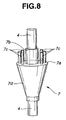
- the joint 7 is formed into an inverse-triangular shape in cross-section extended upwardly toward the stack 4, and the leading ends of the stack 4 and the polybutene pipes 6 are connected to an extension plane 7a (diameter: 150 mm) of the joint 7.
- the extension plane 7a has a connection port 7b to be connected to the stack 4, and a plurality of vertical holes 7c.
- push-locks to be described later are mounted in the vertical holes 7c, and the leading ends of the polybutene pipes 6 are connected thereto.
- the difference in height between the floor slab 2 and the joint 7 is set at 2.5 m.
- the fluid or waste water in the stack 4 is dropped while being accelerated in the vertical direction (with a nearly constant flow rate).
- the fluid or waste water from each of the appliances on each story flows in the transversely extending portion of the polybutene pipe 6 placed on the floor slab 2, and dropped in the downwardly extending portion of the polybutene pipe 6 while being increased in vertical velocity component due to the difference in height (2.5 m) between the floor slab 2 and the joint 7.
- reference numeral 7h designates a valve provided at the leading end of the drainage pipe 6.
- the valve 7h has a counter-flow preventive function and/or a flow control function.
- Fig. 2 is a view showing a first example of the joint 7 of the building drainage system according to the present invention.
- the joint 7 is configured as a hard synthetic resin joint sized such that the outside diameter is 150 mm, the diameter of a stack connection port 7b is 100 mm, and the length is 400 mm.
- the joint 7 is formed into an inverse-triangular shape in cross-section in which eight vertical holes 7c are formed around the connection port 7b.
- the polybutene pipes 6 are connected to the vertical holes 7c.
- a fluid flowing from the polybutene pipes 6 in the joint 7 is restricted in a space (restriction portion) 7d formed into an inverse-triangular shape in cross-section, to be thus naturally combined to a fluid flowing from the stack 4 in the joint 7.
- the fluid flowing down in the stack 4 is uniformly, vertically dropped in the central portion of the joint 7, while the fluid vertically accelerated in the polybutene pipes 6 connected to the vertical holes 7c is dropped in the joint 7. Then, the fluid from the polybutene pipes 6 are combined to the fluid from the stack 4 at the restriction portion 7d formed into the inverse-triangular shape, and the fluids thus combined flow in the stack 4 connected to the lower end of the joint 7. In this way, the fluid in the polybutene pipes 6 accelerated in the vertical direction is relatively easily combined to the fluid in the stack 4, so that a negative pressure occurs in the joint 7, to cause an effect of further sucking the fluid from the polybutene pipes 6.
- a flap valve made from a thin rubber may be provided on the leading end of the polybutene pipe 6, to prevent occurrence of counter-flow on the polybutene pipe 6 side.
- a portion, of the stack 4 passing through a fire protection partition wall, may be covered with a metal sheath pipe.
- Fig. 3 is a view showing a second example of the joint 7 of the building drainage system according to the present invention.
- the joint 7 is configured as a hard synthetic resin joint sized such that the outside diameter is 200 mm, the diameter of a stack connection port 7b is 100 mm, and the length is 400 mm.
- the joint 7 has a curvedly expanded portion 7e disposed on the upper side and a restriction portion 7d recessed inwardly disposed on the lower side.
- the stack 4 is vertically connected to the center of the curvedly expanded portion 7e and the restriction portion 7d.
- Eight vertical holes 7c are formed in the outer peripheral portion of the curvedly expanded portion 7e, and the polybutene pipes 6 are connected to the vertical holes 7c.
- a fluid vertically accelerated flows from the polybutene pipes 6 connected to the vertical holes 7c in the joint 7, being combined to a fluid in the stack 4 at the restriction portion 7d of the joint 7, and easily enters in the stack 4 connected to the lower end of the joint 7. Accordingly, a negative pressure occurs in the joint 7, to cause an effect of further sucking the fluid on the polybutene pipe 6 side.
- Fig. 4 is a view showing a third example of the joint 7 of the building drainage system according to the present invention.
- This joint 7 has a curvedly expanded portion 7e disposed on the upper side, and a curvedly expanded portion 7f disposed on the lower side in such a manner as to be symmetrical to the curvedly expanded portion 7e.
- Both the expanded portions 7e and 7f are connected to each other via a coupling joint 7g.
- Such a joint 7 has a desirable pressure-proof structure.
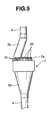
- Fig. 5 is a view showing a fourth example of the joint 7 of the building drainage system according to the present invention.
- the joint 7 is formed into an inverse truncated cone in which the upper end has a diameter of 200 mm and the lower end has a diameter of 100 mm.
- a plurality of vertical holes 7c for supporting the polybutene pipes 6 are collectively disposed on one side of the upper end portion, and the stack 4 is disposed at a position offset from the vertical holes 7c. Even in this joint 7, a combined space is formed by a restriction portion 7d whose diameter becomes smaller toward the lower side.
- the offset of the stack 4 exhibits a merit of reducing the ventilation resistance formed in the combined portion, to relieve a variation in maximum pressure in a portion of the stack 4 near the story directly under the combined portion, thereby making large the allowable flow rate of the stack 4.
- Fig. 6 is a view showing a fifth example of the joint 7 of the building drainage system according to the present invention.
- the joint 7 is formed into an elongated shape with its central portion expanded.
- a stack connection port 7b connected to the upper stack 4 is connected to the joint 7 while being offset on one side (left side, in the figure) of the joint 7, and correspondingly a plurality of vertical holes 7c are offset on the stack 4 side (on the right side, in the figure).
- Fig. 7 is a view showing a sixth example of the joint 7 of the building drainage system according to the present invention.
- a stack connection port 7b connected to the upper stack 4 is connected to the joint 7 while being offset on one side (left side, in the figure) of the joint 7, and a plurality of vertical holes 7c are disposed while being tilted at 45° with respect to the stack connection port 7b.
- the polybutene pipes 6 are connected to the vertical holes 7c.
- the polybutene pipes 6 are bundled in a ventilation pipe 9 and are inserted from above.
- a fluid from the stack 4 flows down along the side surface of the joint 7 into the joint 7, and a fluid from the polybutene pipes 6 flows toward the fluid from the stack 4 in the joint 7. Then, the fluids thus combined flow in the lower stack 4.
- the vertical holes 7c can be freely disposed around the stack 4.
- the vertical holes 7c can be disposed while being divided on the right and left sides.
- the structure of the joint 7 can be flattened and is usable in the narrow space.
- Figs. 9 and 10 are views each showing one example of a push-lock 20 connectable with a single motion, which ca used for connection of the drainage pipe 6 of the present invention, wherein Fig. 9 is a sectional view showing a state before the polybutene pipe 6 is mounted in the push-lock 20, and Fig. 10 is a sectional view showing a state after the polybutene pipe 6 is mounted in the push-lock.
- a grab ring 22, a washer 23, and an 0-ring 24 are mounted in a socket 21 of the push-lock 20, and a cap 25 for supporting the grab ring 22, washer 23 and O-ring 24 is screwed in the socket 21.
- the socket 21 has a female thread portion 26 to be screwed with the vertical hole 7c of the joint 7, or the water-service terminal appliance 5 or bent pipe 8.
- a collar 27 is fitted in the leading end of the polybutene pipe 6, and the polybutene pipe 6 is inserted in the cap 25. At this time, the grab ring 22 bites the outer surface of the polybutene pipe 6, to mount the polybutene pipe 6 in the push lock 20. In this way, the polybutene pipe 6 is certainly, simply mounted in the push-lock 20.
- the feature of the present invention in which the drainage pipes are reduced in diameter and unified for each appliance, can be combined with an already available cold water/hot water supply system into a sheath pipe-header system which is expected as an advanced water piping system as a whole.
- a water piping system is advantageous in exhibiting a resistance against high-temperature and corrosion, and in eliminating a skilled technique for mounting the pipes because the pipes can be laid out with no slope, thereby significantly reducing the burden of a worker.
- the building drainage system of the present invention therefore, is expected as a future global, generalized building drainage system.
- waste water is drained in the stack for each appliance, it is possible not only to obtain a merit in terms of construction of a building and maintenance and management of the building, but also to perform the separation and collection of various kinds of waste water by using the stacks for each application and hence to realize the reuse of waste water and the recovery of heat and organic matters.
- This makes it possible to effectively use a small-and-medium sized facility capable of realizing water-saving and recovery of head and organic matter for each group of houses or each housing complex, and hence to contribute to the future global environmental problem.
Landscapes
- Engineering & Computer Science (AREA)
- Structural Engineering (AREA)
- Environmental & Geological Engineering (AREA)
- Health & Medical Sciences (AREA)
- Life Sciences & Earth Sciences (AREA)
- Hydrology & Water Resources (AREA)
- Public Health (AREA)
- Water Supply & Treatment (AREA)
- Sink And Installation For Waste Water (AREA)
- Devices That Are Associated With Refrigeration Equipment (AREA)
- Curing Cements, Concrete, And Artificial Stone (AREA)
Claims (13)
- Gebäudeabflusssystem, umfassend:worin das kombinierte Verbindungsstück zum Anschließen des einen oder der mehreren Geräteabflussrohre des einen oder der mehreren Geräte eines bestimmten Stockwerks an einer Ebene unterhalb jener der Fußbodenplatte dieses Stockwerks liegt und um einen Abstand im Bereich von 100 cm oder mehr unter der Ebene des sich transversal erstreckenden Abschnitts des kombinierten Verbindungsstücks liegt, und worin jedes des einen oder der mehreren Geräteabflussrohre an das kombinierte Verbindungsstück angeschlossen ist und dabei in Bezug auf die vertikale Linie um einen Winkel in einem Bereich von weniger als 45° geneigt ist, um einem in dem einen oder den mehreren Geräteabflussrohren fließenden Fluid eine Geschwindigkeitskomponente zu übertragen, damit sich das Fluid mit einem im Abflussschacht oder im kombinierten Verbindungsstück fließenden Fluid vereinigt.einen Abflussschacht (4), der in vertikaler Richtung durch Stockwerke hindurch (1, 2) verläuft;ein oder mehrere Geräteabflussrohre (6), die an einem oder mehreren entsprechenden Installationsanschlussgeräten (5) in den Stockwerken angeschlossen sind, wobei alle des einen oder der mehreren Geräteabflussrohre (6) einen sich transversal erstreckenden Abschnitt und stromabwärts dessen einen sich nach unten erstreckenden Abschnitt umfassen; undein kombiniertes Verbindungsstück (7), um jedes des einen oder der mehreren Geräteabflussrohre (6) an den Abflussschacht anzuschließen;
- Gebäudeabflusssystem nach Anspruch 1, worin der spezifische Abstand im Bereich von 200 cm oder mehr liegt.
- Gebäudeabflusssystem nach Anspruch 1, worin der spezifische Abstand der vertikalen Höhe eines Stockwerks entspricht.
- Gebäudeabflusssystem nach einem der vorangegangenen Ansprüche, worin der spezifische Winkel im Bereich von weniger als 30° liegt.
- Gebäudeabflusssystem nach einem der vorangegangenen Ansprüche, worin der spezifische Winkel in einem Bereich von weniger als 15° liegt.
- Gebäudeabflusssystem nach einem der vorangegangenen Ansprüche, worin jedes der Geräteabflussrohre vertikal am kombinierten Verbindungsstück angeschlossen ist.
- Gebäudeabflusssystem nach einem der vorangegangenen Ansprüche, worin die Geräteabflussrohre einzeln am kombinierten Verbindungsstück angeschlossen sind.
- Gebäudeabflusssystem nach einem der vorangegangenen Ansprüche, worin alle Geräteabflussrohre den gleichen Durchmesser aufweisen.
- Gebäudeabflusssystem nach einem der vorangegangenen Ansprüche, worin jedes der Geräteabflussrohre ein biegsames Harzrohr ist.
- Gebäudeabflusssystem nach einem der vorangegangenen Ansprüche, worin die Geräteabflussrohre in jedem der Stockwerke an den Fußbodenplatten des Stockwerks ohne Neigung angeordnet sind.
- Gebäudeabflusssystem nach einem der vorangegangenen Ansprüche, worin ein an den Abflussschacht anzuschließender Abschnitt eines jeden der Geräteabflussrohre mit einem Ventil zur Verhinderung einer Gegenflusses ausgestattet ist.
- Gebäudeabflusssystem nach einem der vorangegangenen Ansprüche, worin ein an den Abflussschacht anzuschließender Abschnitt eines jeden der Geräteabflussrohre mit einem Flussregelungsventil ausgestattet ist.
- Gebaudeabflusssystem nach einem der vorangegangenen Ansprüche, worin ein Steckverbinder, der mit einer einzigen Bewegung anschließbar ist, am Verbindungsstück und an dem/den Gerät(en) angebracht ist, wobei der Steckverbinder einen O-Ring zur Verhinderung eines Wasseraustritts und einen Greifring, der die Außenoberfläche des Geräteabflussrohrs greift, um das Rohr im Steckverbinder anzubringen, umfasst.
Applications Claiming Priority (2)
| Application Number | Priority Date | Filing Date | Title |
|---|---|---|---|
| JP11107251A JP2000297447A (ja) | 1999-04-14 | 1999-04-14 | 建築排水システム |
| JP10725199 | 1999-04-14 |
Publications (3)
| Publication Number | Publication Date |
|---|---|
| EP1045076A2 EP1045076A2 (de) | 2000-10-18 |
| EP1045076A3 EP1045076A3 (de) | 2002-01-23 |
| EP1045076B1 true EP1045076B1 (de) | 2005-07-06 |
Family
ID=14454323
Family Applications (1)
| Application Number | Title | Priority Date | Filing Date |
|---|---|---|---|
| EP00303153A Expired - Lifetime EP1045076B1 (de) | 1999-04-14 | 2000-04-14 | Drainagesystem für ein Gebäude |
Country Status (5)
| Country | Link |
|---|---|
| US (1) | US6425217B1 (de) |
| EP (1) | EP1045076B1 (de) |
| JP (1) | JP2000297447A (de) |
| AT (1) | ATE299206T1 (de) |
| DE (1) | DE60021136T2 (de) |
Families Citing this family (27)
| Publication number | Priority date | Publication date | Assignee | Title |
|---|---|---|---|---|
| JP2002121787A (ja) * | 2000-10-17 | 2002-04-26 | Bridgestone Corp | 建築排水システム |
| DE10062424A1 (de) * | 2000-12-14 | 2002-07-04 | Mete Demiriz | Rohrleitungssystem, insbesondere zur Abführung von Abwässern in Gebäudeinstallationen |
| JP2003013477A (ja) * | 2001-07-02 | 2003-01-15 | Bridgestone Corp | 建築排水システム |
| JP2003013482A (ja) * | 2001-07-02 | 2003-01-15 | Bridgestone Corp | トイレユニット |
| JP2003213771A (ja) * | 2002-01-25 | 2003-07-30 | Toto Ltd | 粉砕装置 |
| JP2004019297A (ja) * | 2002-06-18 | 2004-01-22 | Bridgestone Corp | 排水システムおよび排水方法 |
| JP2004162527A (ja) * | 2004-02-04 | 2004-06-10 | Bridgestone Corp | トイレユニット |
| JP2005307733A (ja) * | 2004-03-22 | 2005-11-04 | Bridgestone Corp | 雨水排水用集合枡 |
| JP2006037455A (ja) * | 2004-07-26 | 2006-02-09 | Asahi Kasei Homes Kk | 排水構造 |
| JP4643282B2 (ja) * | 2005-01-26 | 2011-03-02 | 株式会社ブリヂストン | 建築排水システム及びこれに用いる器具排水管ユニット |
| WO2006129719A1 (ja) * | 2005-06-02 | 2006-12-07 | Bridgestone Corporation | 貯水機能付き排水システム |
| NZ542313A (en) * | 2005-09-09 | 2008-03-28 | Anthony Bicknell | A graffiti security system |
| JP2007315037A (ja) * | 2006-05-25 | 2007-12-06 | Bridgestone Corp | 貯水部を備えたサイフォン排水システム |
| JP4782628B2 (ja) * | 2006-07-13 | 2011-09-28 | 株式会社ブリヂストン | サイフォン排水システム |
| US20110017840A1 (en) * | 2006-09-08 | 2011-01-27 | Sabian Family Trust | Grafitti Prevention System |
| JP2008111318A (ja) * | 2006-10-31 | 2008-05-15 | Bridgestone Corp | 立て管合流継ぎ手及びそれを用いた排水システムの構築方法 |
| JP5021291B2 (ja) * | 2006-12-25 | 2012-09-05 | 株式会社ブリヂストン | 合流部構造 |
| JP2008297819A (ja) * | 2007-05-31 | 2008-12-11 | Bridgestone Corp | 配管洗浄システム、配管洗浄方法 |
| USD589127S1 (en) | 2007-08-16 | 2009-03-24 | Cornwall Kenneth R | Plumbing fitting |
| CN102330453B (zh) * | 2011-06-01 | 2013-11-27 | 王凤蕊 | 防返溢管道接入装置 |
| US10301804B2 (en) | 2013-07-12 | 2019-05-28 | Daniel Grenier | Method and system of removing debris from piping in a high-rise building plumbing network |
| JP6447731B2 (ja) * | 2015-07-17 | 2019-01-09 | 富士通株式会社 | 熱輸送装置及び電子装置 |
| US11105076B1 (en) | 2015-11-18 | 2021-08-31 | Vista Water Group, Llc | Water drain management apparatus used with autoclaves, sterilizers or other devices in a clinical facility |
| US11492789B1 (en) * | 2015-11-18 | 2022-11-08 | Vista Water Group, Llc | Fluid collector for receiving fluids of different densities and providing heat exchange |
| US11105077B1 (en) | 2015-11-18 | 2021-08-31 | Vista Water Group, Llc | Water drain management apparatus used with autoclaves, sterilizers or other devices in a clinical facility |
| US11479953B1 (en) * | 2020-05-19 | 2022-10-25 | Vista Water Group, Llc | Anti-backflow plumbing fitting |
| JP7445587B2 (ja) | 2020-12-08 | 2024-03-07 | 株式会社ブリヂストン | サイホン排水システム |
Family Cites Families (16)
| Publication number | Priority date | Publication date | Assignee | Title |
|---|---|---|---|---|
| US2202147A (en) * | 1939-06-03 | 1940-05-28 | Gerriets Fred | Emplacement former |
| FR1111659A (fr) * | 1954-09-21 | 1956-03-02 | Tronçon standard de canalisations collectrices de vidange de résidus liquides et solides, constituant un bloc-étage | |
| CH459907A (fr) * | 1967-07-14 | 1968-07-15 | Paul Honegger Pierre | Colonne de chute |
| US3707165A (en) * | 1970-08-10 | 1972-12-26 | Joel S Stahl | Plastic plumbing wall |
| US3853140A (en) * | 1971-06-14 | 1974-12-10 | Cast Iron Soil Pipe Inst | Drainage system |
| FR2240322A1 (en) * | 1973-08-10 | 1975-03-07 | Armosig | Branch junction piece for waste water pipes - has lateral break-fall ramp and air compensation chamber |
| US4073018A (en) * | 1975-03-31 | 1978-02-14 | Mckenney's, Inc. | Internal back vent system |
| US4038737A (en) * | 1975-09-05 | 1977-08-02 | Bretone Jr John | Method of replacing plumbing |
| SE409480B (sv) * | 1977-12-14 | 1979-08-20 | Electrolux Ab | Sett att transportera avloppsvatten medelst vakuum |
| US4839927A (en) * | 1986-11-14 | 1989-06-20 | Nishihara Engineering Company, Ltd. | Drainage system in multi-story building |
| US4860503A (en) * | 1987-06-22 | 1989-08-29 | Palmer Winston H | Plumbing apparatus |
| US5076310A (en) * | 1989-02-23 | 1991-12-31 | Alexander Barenburg | Framed wall with a prefabricated underfloor drain line and method of manufacture |
| JPH0369894A (ja) * | 1989-08-09 | 1991-03-26 | Bridgestone Corp | パイプ継手 |
| JPH0642019A (ja) * | 1992-07-23 | 1994-02-15 | Sekisui Chem Co Ltd | 排水配管システム |
| JP3086898B2 (ja) * | 1994-03-31 | 2000-09-11 | 松下電工株式会社 | 管継手 |
| JP2000074260A (ja) * | 1998-09-01 | 2000-03-14 | Sekisui Chem Co Ltd | 住居内の排水用配管構造 |
-
1999
- 1999-04-14 JP JP11107251A patent/JP2000297447A/ja active Pending
-
2000
- 2000-04-14 DE DE60021136T patent/DE60021136T2/de not_active Expired - Lifetime
- 2000-04-14 EP EP00303153A patent/EP1045076B1/de not_active Expired - Lifetime
- 2000-04-14 US US09/549,701 patent/US6425217B1/en not_active Expired - Lifetime
- 2000-04-14 AT AT00303153T patent/ATE299206T1/de not_active IP Right Cessation
Also Published As
| Publication number | Publication date |
|---|---|
| JP2000297447A (ja) | 2000-10-24 |
| DE60021136T2 (de) | 2006-05-11 |
| ATE299206T1 (de) | 2005-07-15 |
| EP1045076A3 (de) | 2002-01-23 |
| US6425217B1 (en) | 2002-07-30 |
| EP1045076A2 (de) | 2000-10-18 |
| DE60021136D1 (de) | 2005-08-11 |
Similar Documents
| Publication | Publication Date | Title |
|---|---|---|
| EP1045076B1 (de) | Drainagesystem für ein Gebäude | |
| KR102030995B1 (ko) | 건축물의 배수파이프 화재확산 방지장치 | |
| US6068023A (en) | Valve for clearing air conditioning drain lines | |
| US5722458A (en) | Valve for clearing air conditioning drain lines | |
| US6038710A (en) | Sewage removal system | |
| CA2367959A1 (en) | Plumber's flange and method for using the same | |
| US4597404A (en) | Plumbing fixture | |
| JP4252553B2 (ja) | 建造物内の排水設備 | |
| US4449741A (en) | Waste plumbing installation and fittings therefor | |
| KR20140136230A (ko) | 누수 배수장치 | |
| CN207812619U (zh) | 排水管二次保护结构 | |
| KR101854207B1 (ko) | 전자제품에서 발생되는 폐수의 연속 배출장치 | |
| JPH0374730B2 (de) | ||
| JP4390565B2 (ja) | 排水アダプタ及び排水構造 | |
| JP2703829B2 (ja) | 排水システム | |
| DE19959065A1 (de) | Schachtbauwerk | |
| JP4907640B2 (ja) | 排水配管の継手装置 | |
| JP2003201727A (ja) | 建築排水システム | |
| JP3447783B2 (ja) | 通気口付き管継手 | |
| CN212612889U (zh) | 一种tod项目餐饮废水防淤积系统 | |
| JP2022100842A (ja) | 配管、配管システム、配管の設置方法および管詰まりまたは溢液検出方法 | |
| US7617835B2 (en) | Hydrant assist kit | |
| CN219547927U (zh) | 一种集成式的排水管组件 | |
| JP3099228B2 (ja) | 排水集合継手 | |
| JP2001279795A (ja) | トイレ装置 |
Legal Events
| Date | Code | Title | Description |
|---|---|---|---|
| PUAI | Public reference made under article 153(3) epc to a published international application that has entered the european phase |
Free format text: ORIGINAL CODE: 0009012 |
|
| AK | Designated contracting states |
Kind code of ref document: A2 Designated state(s): AT BE CH CY DE DK ES FI FR GB GR IE IT LI LU MC NL PT SE |
|
| AX | Request for extension of the european patent |
Free format text: AL;LT;LV;MK;RO;SI |
|
| PUAL | Search report despatched |
Free format text: ORIGINAL CODE: 0009013 |
|
| AK | Designated contracting states |
Kind code of ref document: A3 Designated state(s): AT BE CH CY DE DK ES FI FR GB GR IE IT LI LU MC NL PT SE |
|
| AX | Request for extension of the european patent |
Free format text: AL;LT;LV;MK;RO;SI |
|
| 17P | Request for examination filed |
Effective date: 20020301 |
|
| AKX | Designation fees paid |
Free format text: AT BE CH CY DE DK ES FI FR GB GR IE IT LI LU MC NL PT SE |
|
| 17Q | First examination report despatched |
Effective date: 20040705 |
|
| GRAP | Despatch of communication of intention to grant a patent |
Free format text: ORIGINAL CODE: EPIDOSNIGR1 |
|
| GRAS | Grant fee paid |
Free format text: ORIGINAL CODE: EPIDOSNIGR3 |
|
| GRAA | (expected) grant |
Free format text: ORIGINAL CODE: 0009210 |
|
| AK | Designated contracting states |
Kind code of ref document: B1 Designated state(s): AT BE CH CY DE DK ES FI FR GB GR IE IT LI LU MC NL PT SE |
|
| PG25 | Lapsed in a contracting state [announced via postgrant information from national office to epo] |
Ref country code: IT Free format text: LAPSE BECAUSE OF FAILURE TO SUBMIT A TRANSLATION OF THE DESCRIPTION OR TO PAY THE FEE WITHIN THE PRESCRIBED TIME-LIMIT;WARNING: LAPSES OF ITALIAN PATENTS WITH EFFECTIVE DATE BEFORE 2007 MAY HAVE OCCURRED AT ANY TIME BEFORE 2007. THE CORRECT EFFECTIVE DATE MAY BE DIFFERENT FROM THE ONE RECORDED. Effective date: 20050706 Ref country code: BE Free format text: LAPSE BECAUSE OF FAILURE TO SUBMIT A TRANSLATION OF THE DESCRIPTION OR TO PAY THE FEE WITHIN THE PRESCRIBED TIME-LIMIT Effective date: 20050706 Ref country code: NL Free format text: LAPSE BECAUSE OF FAILURE TO SUBMIT A TRANSLATION OF THE DESCRIPTION OR TO PAY THE FEE WITHIN THE PRESCRIBED TIME-LIMIT Effective date: 20050706 Ref country code: LI Free format text: LAPSE BECAUSE OF FAILURE TO SUBMIT A TRANSLATION OF THE DESCRIPTION OR TO PAY THE FEE WITHIN THE PRESCRIBED TIME-LIMIT Effective date: 20050706 Ref country code: AT Free format text: LAPSE BECAUSE OF FAILURE TO SUBMIT A TRANSLATION OF THE DESCRIPTION OR TO PAY THE FEE WITHIN THE PRESCRIBED TIME-LIMIT Effective date: 20050706 Ref country code: FI Free format text: LAPSE BECAUSE OF FAILURE TO SUBMIT A TRANSLATION OF THE DESCRIPTION OR TO PAY THE FEE WITHIN THE PRESCRIBED TIME-LIMIT Effective date: 20050706 Ref country code: CH Free format text: LAPSE BECAUSE OF FAILURE TO SUBMIT A TRANSLATION OF THE DESCRIPTION OR TO PAY THE FEE WITHIN THE PRESCRIBED TIME-LIMIT Effective date: 20050706 |
|
| REG | Reference to a national code |
Ref country code: GB Ref legal event code: FG4D |
|
| REG | Reference to a national code |
Ref country code: CH Ref legal event code: EP |
|
| REG | Reference to a national code |
Ref country code: IE Ref legal event code: FG4D |
|
| REF | Corresponds to: |
Ref document number: 60021136 Country of ref document: DE Date of ref document: 20050811 Kind code of ref document: P |
|
| PG25 | Lapsed in a contracting state [announced via postgrant information from national office to epo] |
Ref country code: DK Free format text: LAPSE BECAUSE OF FAILURE TO SUBMIT A TRANSLATION OF THE DESCRIPTION OR TO PAY THE FEE WITHIN THE PRESCRIBED TIME-LIMIT Effective date: 20051006 Ref country code: SE Free format text: LAPSE BECAUSE OF FAILURE TO SUBMIT A TRANSLATION OF THE DESCRIPTION OR TO PAY THE FEE WITHIN THE PRESCRIBED TIME-LIMIT Effective date: 20051006 Ref country code: GR Free format text: LAPSE BECAUSE OF FAILURE TO SUBMIT A TRANSLATION OF THE DESCRIPTION OR TO PAY THE FEE WITHIN THE PRESCRIBED TIME-LIMIT Effective date: 20051006 |
|
| PG25 | Lapsed in a contracting state [announced via postgrant information from national office to epo] |
Ref country code: PT Free format text: LAPSE BECAUSE OF FAILURE TO SUBMIT A TRANSLATION OF THE DESCRIPTION OR TO PAY THE FEE WITHIN THE PRESCRIBED TIME-LIMIT Effective date: 20051212 |
|
| NLV1 | Nl: lapsed or annulled due to failure to fulfill the requirements of art. 29p and 29m of the patents act | ||
| REG | Reference to a national code |
Ref country code: CH Ref legal event code: PL |
|
| ET | Fr: translation filed | ||
| PG25 | Lapsed in a contracting state [announced via postgrant information from national office to epo] |
Ref country code: IE Free format text: LAPSE BECAUSE OF NON-PAYMENT OF DUE FEES Effective date: 20060414 |
|
| PG25 | Lapsed in a contracting state [announced via postgrant information from national office to epo] |
Ref country code: MC Free format text: LAPSE BECAUSE OF NON-PAYMENT OF DUE FEES Effective date: 20060430 |
|
| PLBE | No opposition filed within time limit |
Free format text: ORIGINAL CODE: 0009261 |
|
| STAA | Information on the status of an ep patent application or granted ep patent |
Free format text: STATUS: NO OPPOSITION FILED WITHIN TIME LIMIT |
|
| 26N | No opposition filed |
Effective date: 20060407 |
|
| REG | Reference to a national code |
Ref country code: IE Ref legal event code: MM4A |
|
| PG25 | Lapsed in a contracting state [announced via postgrant information from national office to epo] |
Ref country code: LU Free format text: LAPSE BECAUSE OF NON-PAYMENT OF DUE FEES Effective date: 20060414 |
|
| PG25 | Lapsed in a contracting state [announced via postgrant information from national office to epo] |
Ref country code: CY Free format text: LAPSE BECAUSE OF FAILURE TO SUBMIT A TRANSLATION OF THE DESCRIPTION OR TO PAY THE FEE WITHIN THE PRESCRIBED TIME-LIMIT Effective date: 20050706 |
|
| PG25 | Lapsed in a contracting state [announced via postgrant information from national office to epo] |
Ref country code: ES Free format text: LAPSE BECAUSE OF NON-PAYMENT OF DUE FEES Effective date: 20060430 |
|
| PGFP | Annual fee paid to national office [announced via postgrant information from national office to epo] |
Ref country code: GB Payment date: 20100325 Year of fee payment: 11 |
|
| PGFP | Annual fee paid to national office [announced via postgrant information from national office to epo] |
Ref country code: FR Payment date: 20100521 Year of fee payment: 11 |
|
| PGFP | Annual fee paid to national office [announced via postgrant information from national office to epo] |
Ref country code: DE Payment date: 20100430 Year of fee payment: 11 |
|
| REG | Reference to a national code |
Ref country code: DE Ref legal event code: R119 Ref document number: 60021136 Country of ref document: DE |
|
| REG | Reference to a national code |
Ref country code: DE Ref legal event code: R119 Ref document number: 60021136 Country of ref document: DE |
|
| GBPC | Gb: european patent ceased through non-payment of renewal fee |
Effective date: 20110414 |
|
| REG | Reference to a national code |
Ref country code: FR Ref legal event code: ST Effective date: 20111230 |
|
| PG25 | Lapsed in a contracting state [announced via postgrant information from national office to epo] |
Ref country code: FR Free format text: LAPSE BECAUSE OF NON-PAYMENT OF DUE FEES Effective date: 20110502 |
|
| PG25 | Lapsed in a contracting state [announced via postgrant information from national office to epo] |
Ref country code: GB Free format text: LAPSE BECAUSE OF NON-PAYMENT OF DUE FEES Effective date: 20110414 |
|
| PG25 | Lapsed in a contracting state [announced via postgrant information from national office to epo] |
Ref country code: DE Free format text: LAPSE BECAUSE OF NON-PAYMENT OF DUE FEES Effective date: 20111031 |