EP1045114B1 - Turbine à gaz terrestre ayant un système de refroidissement et procédé de refroidissement - Google Patents
Turbine à gaz terrestre ayant un système de refroidissement et procédé de refroidissement Download PDFInfo
- Publication number
- EP1045114B1 EP1045114B1 EP00303123A EP00303123A EP1045114B1 EP 1045114 B1 EP1045114 B1 EP 1045114B1 EP 00303123 A EP00303123 A EP 00303123A EP 00303123 A EP00303123 A EP 00303123A EP 1045114 B1 EP1045114 B1 EP 1045114B1
- Authority
- EP
- European Patent Office
- Prior art keywords
- gas turbine
- cooling air
- stage
- diaphragm
- nozzle
- Prior art date
- Legal status (The legal status is an assumption and is not a legal conclusion. Google has not performed a legal analysis and makes no representation as to the accuracy of the status listed.)
- Expired - Lifetime
Links
- 238000001816 cooling Methods 0.000 title claims description 53
- 238000000034 method Methods 0.000 title claims description 7
- 125000006850 spacer group Chemical group 0.000 claims description 14
- 239000007789 gas Substances 0.000 description 19
- 238000000605 extraction Methods 0.000 description 4
- 238000010926 purge Methods 0.000 description 4
- 230000001133 acceleration Effects 0.000 description 3
- 230000008878 coupling Effects 0.000 description 3
- 238000010168 coupling process Methods 0.000 description 3
- 238000005859 coupling reaction Methods 0.000 description 3
- 239000000567 combustion gas Substances 0.000 description 2
- 239000000411 inducer Substances 0.000 description 2
- 230000003068 static effect Effects 0.000 description 2
- OKTJSMMVPCPJKN-UHFFFAOYSA-N Carbon Chemical compound [C] OKTJSMMVPCPJKN-UHFFFAOYSA-N 0.000 description 1
- 229910052799 carbon Inorganic materials 0.000 description 1
- 238000010276 construction Methods 0.000 description 1
- 239000002826 coolant Substances 0.000 description 1
- 230000003071 parasitic effect Effects 0.000 description 1
- 238000010248 power generation Methods 0.000 description 1
- 238000011084 recovery Methods 0.000 description 1
- 230000001052 transient effect Effects 0.000 description 1
- XLYOFNOQVPJJNP-UHFFFAOYSA-N water Substances O XLYOFNOQVPJJNP-UHFFFAOYSA-N 0.000 description 1
Images



Classifications
-
- F—MECHANICAL ENGINEERING; LIGHTING; HEATING; WEAPONS; BLASTING
- F01—MACHINES OR ENGINES IN GENERAL; ENGINE PLANTS IN GENERAL; STEAM ENGINES
- F01D—NON-POSITIVE DISPLACEMENT MACHINES OR ENGINES, e.g. STEAM TURBINES
- F01D9/00—Stators
- F01D9/06—Fluid supply conduits to nozzles or the like
- F01D9/065—Fluid supply or removal conduits traversing the working fluid flow, e.g. for lubrication-, cooling-, or sealing fluids
-
- E—FIXED CONSTRUCTIONS
- E02—HYDRAULIC ENGINEERING; FOUNDATIONS; SOIL SHIFTING
- E02B—HYDRAULIC ENGINEERING
- E02B3/00—Engineering works in connection with control or use of streams, rivers, coasts, or other marine sites; Sealings or joints for engineering works in general
- E02B3/04—Structures or apparatus for, or methods of, protecting banks, coasts, or harbours
- E02B3/06—Moles; Piers; Quays; Quay walls; Groynes; Breakwaters ; Wave dissipating walls; Quay equipment
-
- E—FIXED CONSTRUCTIONS
- E02—HYDRAULIC ENGINEERING; FOUNDATIONS; SOIL SHIFTING
- E02B—HYDRAULIC ENGINEERING
- E02B3/00—Engineering works in connection with control or use of streams, rivers, coasts, or other marine sites; Sealings or joints for engineering works in general
- E02B3/04—Structures or apparatus for, or methods of, protecting banks, coasts, or harbours
- E02B3/12—Revetment of banks, dams, watercourses, or the like, e.g. the sea-floor
- E02B3/14—Preformed blocks or slabs for forming essentially continuous surfaces; Arrangements thereof
-
- E—FIXED CONSTRUCTIONS
- E02—HYDRAULIC ENGINEERING; FOUNDATIONS; SOIL SHIFTING
- E02D—FOUNDATIONS; EXCAVATIONS; EMBANKMENTS; UNDERGROUND OR UNDERWATER STRUCTURES
- E02D17/00—Excavations; Bordering of excavations; Making embankments
- E02D17/20—Securing of slopes or inclines
-
- F—MECHANICAL ENGINEERING; LIGHTING; HEATING; WEAPONS; BLASTING
- F01—MACHINES OR ENGINES IN GENERAL; ENGINE PLANTS IN GENERAL; STEAM ENGINES
- F01D—NON-POSITIVE DISPLACEMENT MACHINES OR ENGINES, e.g. STEAM TURBINES
- F01D5/00—Blades; Blade-carrying members; Heating, heat-insulating, cooling or antivibration means on the blades or the members
- F01D5/02—Blade-carrying members, e.g. rotors
- F01D5/08—Heating, heat-insulating or cooling means
- F01D5/085—Heating, heat-insulating or cooling means cooling fluid circulating inside the rotor
- F01D5/088—Heating, heat-insulating or cooling means cooling fluid circulating inside the rotor in a closed cavity
-
- Y—GENERAL TAGGING OF NEW TECHNOLOGICAL DEVELOPMENTS; GENERAL TAGGING OF CROSS-SECTIONAL TECHNOLOGIES SPANNING OVER SEVERAL SECTIONS OF THE IPC; TECHNICAL SUBJECTS COVERED BY FORMER USPC CROSS-REFERENCE ART COLLECTIONS [XRACs] AND DIGESTS
- Y02—TECHNOLOGIES OR APPLICATIONS FOR MITIGATION OR ADAPTATION AGAINST CLIMATE CHANGE
- Y02T—CLIMATE CHANGE MITIGATION TECHNOLOGIES RELATED TO TRANSPORTATION
- Y02T50/00—Aeronautics or air transport
- Y02T50/60—Efficient propulsion technologies, e.g. for aircraft
Definitions
- the present invention relates generally to turbines, particularly but not exclusively to land-based gas turbines for power generation, employing compressor air for cooling the buckets of the third turbine stage.
- air is extracted from the twelfth stage of the compressor and is carried through extraction piping outside the gas turbine, and then supplied through the turbine shell to the stage 3 nozzle.
- relatively low pressure twelfth stage air is used.
- the traditional method of bringing air flow from the machine center line practiced by the assignor of this invention is not possible as the forward wheel cavities require high pressure air to drive their purge circuits. Even with steam cooling of the first two bucket stages, air is required to bathe the turbine wheels to control their temperature during transient and start-up operations.
- the present invention also relates to a method of cooling one stage of a gas turbine comprising a) extracting cooling air from a turbine compressor; b) supplying cooling air to a stationary nozzle adjacent the one stage of the gas turbine; c) establishing a path for the cooling air from the stationary nozzle to a plurality of buckets in the one turbine stage; and d) flowing the cooling air radially outwardly through the plurality of buckets and exhausting the cooling air from radially outer tips of the buckets.
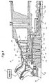
- the turbine section 10 of a gas turbine is partially illustrated.
- the gas turbine of this invention is advantageously utilized in a combined cycle system in which the exhaust gases exiting the gas turbine enter a heat recovery steam generator in which water is converted to steam in the manner of a boiler. Steam thus produced drives one or more steam turbines in which additional work is extracted to drive an additional load, such as a second generator, which, in turn, produces additional electric power.
- a bore tube assembly 32 forms part of the rotor R and rotates with the rotor about the rotor axis A.
- the bore tube assembly includes outer and inner tubes 34 and 36 defining annular steam cooling supply passage 38 and spent stream return passage 40. These passages communicate steam to and from the outer rim of the rotor through sets of radial conduits 42, 44 and axially extending conduits (one shown at 46) circumferentially spaced about the rotor rim for supplying cooling steam to the first and second stage buckets B1 and B2. Return or spent cooling steam flows through similar axially and radially extending conduits, respectively, for flow coaxially from the rotor bore via return passage 40.
- the steam cooling circuit per se, however, forms no part of this invention.
- a passage or conduit 60 is shown extending radially within the vane or airfoil 50, with a generally radially extending, flexible coupling or connector 62 (incorporating a carbon bushing, not shown) carrying the air within the diaphragm 64.
- the connector is operatively connected to a diaphragm insert 66 by means of a spoolie device 68.
- the latter having generally spherically shaped opposite ends, in combination with the flexible coupling 62, accommodate any relative movement between the insert 66 and the diaphragm 64.
- the diaphragm inserts 66 comprise a plurality of part annular segments extending circumferentially about the rotor, with labyrinth seals 90 engaged with cooperating seals 92 on the rotor spacer wheel 22 to prevent leakage of air along the rotor.
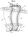
- the air passage changes direction via elbow passage 70 and substantially straight passage 72 to direct the air tangentially (at an angle ⁇ of about 22-23E) into an annular rotor cavity 74, as best seen in Figures 6 and 7 .
- Passage 70 tapers in the flow direction through an elbow portion to a smaller diameter at passage 72, thereby causing acceleration of the cooling air as it is fed into the annular cavity 74.
- the air as supplied to cavity 74 is relatively "still" vis-a-vis the rotor.
- the air is fed tangentially at a speed substantially the same as the rotational speed of the rotor. This results in cooler air being available for the third stage buckets, due to the reduction in relative velocity between the rotor spacer wheel and the air, and the drop in air static temperature due to its tangential acceleration.
- the cooling air moves axially through multiple sets of three passages 76 each (see Figures 3 , 4 and especially 5), with access to the passages permitted by forming the spacer wheel 22 with scalloped areas 78 about its periphery as best seen in Figure 5 .
- While the invention as described relates to air cooling in land based turbines, it can be applied to aircraft turbines as well.
Landscapes
- Engineering & Computer Science (AREA)
- General Engineering & Computer Science (AREA)
- Mechanical Engineering (AREA)
- Civil Engineering (AREA)
- Structural Engineering (AREA)
- Ocean & Marine Engineering (AREA)
- Physics & Mathematics (AREA)
- Environmental & Geological Engineering (AREA)
- Fluid Mechanics (AREA)
- Mining & Mineral Resources (AREA)
- Life Sciences & Earth Sciences (AREA)
- General Life Sciences & Earth Sciences (AREA)
- Paleontology (AREA)
- Turbine Rotor Nozzle Sealing (AREA)
Claims (10)
- Turbine à gaz terrestre comprenant un compresseur (55), une chambre de combustion et une partie turbine (10) avec au moins un premier, un deuxième et un troisième étages (NB), un rotor et un circuit de refroidissement comprenant :un orifice d'admission (56) dans une buse (N3) du troisième étage à partir du compresseur (55) pour assurer un apport d'air de refroidissement du compresseur (60) à la buse (N3) du troisième étage ;au moins un passage (60) s'étendant de manière sensiblement radiale à travers chaque profil aérodynamique de ladite buse (N3) du troisième étage et un distributeur associé (64) dans un espace annulaire (74) entre le rotor et le distributeur ; etdes passages (76, 82) communiquant entre ledit espace annulaire (74) et des aubes individuelles dudit troisième étage et caractérisée en ce quele distributeur (64) présente un insert (66) de distributeur et que ledit au moins un passage (60) comporte un passage en forme de coude (70) et un passage sensiblement rectiligne (72) dans ledit insert (66) de distributeur et qu'il est orienté selon un angle par rapport au distributeur et au moyen duquel ledit air de refroidissement est alimenté dans ledit espace annulaire (74) essentiellement de manière tangentielle au rotor.
- Turbine à gaz selon la revendication 1, dans laquelle ladite partie dudit au moins passage (60) se rétrécit dans le sens de l'écoulement pour accélérer l'air de refroidissement lorsqu'il pénètre dans ledit espace annulaire (74).
- Turbine à gaz selon la revendication 1 ou la revendication 2, dans laquelle ladite partie d'au moins un passage (60) dans ledit distributeur est prévue dans un segment (71) de joint à labyrinthe annulaire de pièce fixé sur ledit distributeur et coopérant avec un joint correspondant (73) sur une roue d'entretoise de rotor située radialement vers l'intérieur de ladite buse (N3) du troisième étage.
- Turbine à gaz selon la revendication 3, dans laquelle des moyens (68) sont prévus pour permettre un déplacement relatif ou une disparité relative entre ladite partie dudit au moins un passage (60) dans ledit segment de joint et dans ledit distributeur.
- Turbine à gaz selon l'une quelconque des revendications dans laquelle ledit orifice d'admission à ladite buse (N3) du troisième étage comporte un collecteur (54) externe à un carter de ladite turbine à gaz.
- Turbine à gaz selon la revendication 3, dans laquelle lesdits passages (76, 82) communiquant entre ledit espace annulaire (74) et lesdites aubes individuelles comportent de multiples ensembles de passages axiaux (76) à travers la roue d'entretoise.
- Turbine à gaz selon la revendication 1, dans laquelle ladite troisième buse (N3) du troisième étage comporte une pluralité de segments (48) partiellement annulaires, chaque segment (48) ayant deux profils aérodynamiques (50, 52) de buse, et dans laquelle ledit orifice d'admission (56) comporte un tube (58) assurant un apport d'air de refroidissement à chaque segment (48), ledit tube (58) fournissant de l'air de refroidissement à chacun desdits deux profils aérodynamiques de buse.
- Procédé de refroidissement du troisième étage d'une turbine à gaz terrestre caractérisé par :a) l'extraction d'air de refroidissement (54) d'un compresseur (55) de turbine ;b) l'apport d'air de refroidissement (56, 58) à une buse fixe adjacente audit troisième étage de la turbine à gaz ;c) l'établissement d'un trajet (76, 82) pour ledit air de refroidissement de ladite buse fixe à une pluralité d'aubes dans ledit troisième étage de turbine ; etd) l'écoulement dudit air de refroidissement radialement vers l'extérieur à travers ladite pluralité d'aubes ainsi que l'évacuation dudit air de refroidissement des extrémités radiales externes desdites aubes ; dans lequel au cours de l'étape c), ledit air de refroidissement est alimenté de façon tangentielle à travers un passage en forme de coude (70) dans un insert (66) de distributeur dans un espace annulaire (74) entourant un rotor de ladite turbine à gaz.
- Procédé selon la revendication 8, dans lequel ledit air de refroidissement est accéléré dans ledit espace annulaire (74).
- Procédé selon la revendication 9, dans lequel ledit air de refroidissement est fourni à ladite buse fixe via un trajet en dehors de ladite turbine à gaz.
Applications Claiming Priority (2)
| Application Number | Priority Date | Filing Date | Title |
|---|---|---|---|
| US29244599A | 1999-04-15 | 1999-04-15 | |
| US292445 | 1999-04-15 |
Publications (3)
| Publication Number | Publication Date |
|---|---|
| EP1045114A2 EP1045114A2 (fr) | 2000-10-18 |
| EP1045114A3 EP1045114A3 (fr) | 2002-10-30 |
| EP1045114B1 true EP1045114B1 (fr) | 2009-10-14 |
Family
ID=23124703
Family Applications (1)
| Application Number | Title | Priority Date | Filing Date |
|---|---|---|---|
| EP00303123A Expired - Lifetime EP1045114B1 (fr) | 1999-04-15 | 2000-04-13 | Turbine à gaz terrestre ayant un système de refroidissement et procédé de refroidissement |
Country Status (5)
| Country | Link |
|---|---|
| US (1) | US6397604B2 (fr) |
| EP (1) | EP1045114B1 (fr) |
| JP (1) | JP4778603B2 (fr) |
| KR (1) | KR20000071653A (fr) |
| DE (1) | DE60043131D1 (fr) |
Families Citing this family (38)
| Publication number | Priority date | Publication date | Assignee | Title |
|---|---|---|---|---|
| US6884023B2 (en) * | 2002-09-27 | 2005-04-26 | United Technologies Corporation | Integral swirl knife edge injection assembly |
| DE10310815A1 (de) * | 2003-03-12 | 2004-09-23 | Rolls-Royce Deutschland Ltd & Co Kg | Wirbelgleichrichter in Röhrenbauweise mit Haltering |
| US6968696B2 (en) | 2003-09-04 | 2005-11-29 | Siemens Westinghouse Power Corporation | Part load blade tip clearance control |
| US7096673B2 (en) | 2003-10-08 | 2006-08-29 | Siemens Westinghouse Power Corporation | Blade tip clearance control |
| US7056088B2 (en) * | 2004-04-21 | 2006-06-06 | General Electric Company | Steam turbine rotor temperature control at oil deflector |
| US7207775B2 (en) * | 2004-06-03 | 2007-04-24 | General Electric Company | Turbine bucket with optimized cooling circuit |
| US7344354B2 (en) * | 2005-09-08 | 2008-03-18 | General Electric Company | Methods and apparatus for operating gas turbine engines |
| US8057157B2 (en) * | 2007-10-22 | 2011-11-15 | General Electric Company | System for delivering air from a multi-stage compressor to a turbine portion of a gas turbine engine |
| US8257015B2 (en) * | 2008-02-14 | 2012-09-04 | General Electric Company | Apparatus for cooling rotary components within a steam turbine |
| US8277170B2 (en) * | 2008-05-16 | 2012-10-02 | General Electric Company | Cooling circuit for use in turbine bucket cooling |
| US8079803B2 (en) | 2008-06-30 | 2011-12-20 | Mitsubishi Heavy Industries, Ltd. | Gas turbine and cooling air supply structure thereof |
| US8167535B2 (en) * | 2008-07-24 | 2012-05-01 | General Electric Company | System and method for providing supercritical cooling steam into a wheelspace of a turbine |
| US20100092280A1 (en) * | 2008-10-14 | 2010-04-15 | General Electric Company | Steam Cooled Direct Fired Coal Gas Turbine |
| US8408866B2 (en) | 2008-11-17 | 2013-04-02 | Rolls-Royce Corporation | Apparatus and method for cooling a turbine airfoil arrangement in a gas turbine engine |
| US8186933B2 (en) * | 2009-03-24 | 2012-05-29 | General Electric Company | Systems, methods, and apparatus for passive purge flow control in a turbine |
| US8206109B2 (en) * | 2009-03-30 | 2012-06-26 | General Electric Company | Turbine blade assemblies with thermal insulation |
| JP4841661B2 (ja) * | 2009-09-25 | 2011-12-21 | 川崎重工業株式会社 | 多段ブラシシールを備えた封止機構 |
| US8578720B2 (en) | 2010-04-12 | 2013-11-12 | Siemens Energy, Inc. | Particle separator in a gas turbine engine |
| US8584469B2 (en) | 2010-04-12 | 2013-11-19 | Siemens Energy, Inc. | Cooling fluid pre-swirl assembly for a gas turbine engine |
| US8613199B2 (en) | 2010-04-12 | 2013-12-24 | Siemens Energy, Inc. | Cooling fluid metering structure in a gas turbine engine |
| US8677766B2 (en) | 2010-04-12 | 2014-03-25 | Siemens Energy, Inc. | Radial pre-swirl assembly and cooling fluid metering structure for a gas turbine engine |
| EP2383435A1 (fr) * | 2010-04-29 | 2011-11-02 | Siemens Aktiengesellschaft | Rail interne creux d'aube de turbine |
| US8671688B2 (en) | 2011-04-13 | 2014-03-18 | General Electric Company | Combined cycle power plant with thermal load reduction system |
| US9222410B2 (en) | 2011-04-13 | 2015-12-29 | General Electric Company | Power plant |
| US9080449B2 (en) | 2011-08-16 | 2015-07-14 | United Technologies Corporation | Gas turbine engine seal assembly having flow-through tube |
| US9011078B2 (en) * | 2012-01-09 | 2015-04-21 | General Electric Company | Turbine vane seal carrier with slots for cooling and assembly |
| US9057275B2 (en) * | 2012-06-04 | 2015-06-16 | Geneal Electric Company | Nozzle diaphragm inducer |
| JP6100626B2 (ja) * | 2013-06-21 | 2017-03-22 | 三菱日立パワーシステムズ株式会社 | ガスタービン |
| DE102013217504A1 (de) * | 2013-09-03 | 2015-03-05 | MTU Aero Engines AG | Strömungsmaschine |
| US9702261B2 (en) | 2013-12-06 | 2017-07-11 | General Electric Company | Steam turbine and methods of assembling the same |
| RU2572515C2 (ru) * | 2014-04-09 | 2016-01-20 | Федеральное государственное бюджетное научное учреждение "Всероссийский научно-исследовательский институт электрификации сельского хозяйства" (ФГБНУ ВИЭСХ) | Устройство охлаждения вала свободной турбины газотурбинной установки |
| US9719425B2 (en) | 2014-05-23 | 2017-08-01 | General Electric Company | Cooling supply circuit for turbomachinery |
| US10378379B2 (en) | 2015-08-27 | 2019-08-13 | General Electric Company | Gas turbine engine cooling air manifolds with spoolies |
| US10030538B2 (en) * | 2015-11-05 | 2018-07-24 | General Electric Company | Gas turbine engine with a vane having a cooling air turning nozzle |
| PL415045A1 (pl) | 2015-12-03 | 2017-06-05 | General Electric Company | Tarcze turbiny i sposoby ich wytwarzania |
| US10519873B2 (en) * | 2016-04-06 | 2019-12-31 | General Electric Company | Air bypass system for rotor shaft cooling |
| US11352896B2 (en) * | 2020-08-21 | 2022-06-07 | Pratt & Whitney Canada Corp. | Tube assembly for a gas turbine engine |
| US11692485B2 (en) | 2021-02-18 | 2023-07-04 | Generai, Electric Company | Gas turbine engine with spoolie fluid transfer connection |
Family Cites Families (16)
| Publication number | Priority date | Publication date | Assignee | Title |
|---|---|---|---|---|
| US3015937A (en) * | 1958-07-03 | 1962-01-09 | James V Giliberty | Temperature modulating system for internal combustion turbines and the like |
| GB938247A (en) * | 1962-03-26 | 1963-10-02 | Rolls Royce | Gas turbine engine having cooled turbine blading |
| US3295823A (en) * | 1965-10-13 | 1967-01-03 | Raymond G H Waugh | Gas turbine cooling distribution system using the blade ring principle |
| US4113406A (en) * | 1976-11-17 | 1978-09-12 | Westinghouse Electric Corp. | Cooling system for a gas turbine engine |
| JPH06102963B2 (ja) * | 1983-12-22 | 1994-12-14 | 株式会社東芝 | ガスタ−ビン空冷翼 |
| JP3142850B2 (ja) * | 1989-03-13 | 2001-03-07 | 株式会社東芝 | タービンの冷却翼および複合発電プラント |
| US5253976A (en) * | 1991-11-19 | 1993-10-19 | General Electric Company | Integrated steam and air cooling for combined cycle gas turbines |
| US5340274A (en) * | 1991-11-19 | 1994-08-23 | General Electric Company | Integrated steam/air cooling system for gas turbines |
| DE69305326T2 (de) * | 1992-02-10 | 1997-05-07 | United Technologies Corp | Ejektor für kühlfluid |
| US5634766A (en) * | 1994-08-23 | 1997-06-03 | General Electric Co. | Turbine stator vane segments having combined air and steam cooling circuits |
| DE19629191C2 (de) * | 1996-07-19 | 1998-05-14 | Siemens Ag | Verfahren zur Kühlung einer Gasturbine |
| JP3442933B2 (ja) * | 1996-07-31 | 2003-09-02 | 三菱重工業株式会社 | 熱回収式ガスタービン |
| JP3416447B2 (ja) * | 1997-03-11 | 2003-06-16 | 三菱重工業株式会社 | ガスタービンの翼冷却空気供給システム |
| JPH10331659A (ja) * | 1997-06-02 | 1998-12-15 | Hitachi Ltd | 発電用ガスタービン及びコンバインド発電システム |
| US6019573A (en) * | 1998-01-29 | 2000-02-01 | Mitsubishi Heavy Industries, Ltd. | Heat recovery type gas turbine |
| DE19824766C2 (de) * | 1998-06-03 | 2000-05-11 | Siemens Ag | Gasturbine sowie Verfahren zur Kühlung einer Turbinenstufe |
-
2000
- 2000-04-12 KR KR1020000019197A patent/KR20000071653A/ko not_active Ceased
- 2000-04-13 EP EP00303123A patent/EP1045114B1/fr not_active Expired - Lifetime
- 2000-04-13 DE DE60043131T patent/DE60043131D1/de not_active Expired - Lifetime
- 2000-04-14 JP JP2000112824A patent/JP4778603B2/ja not_active Expired - Lifetime
-
2001
- 2001-02-01 US US09/773,369 patent/US6397604B2/en not_active Expired - Lifetime
Also Published As
| Publication number | Publication date |
|---|---|
| EP1045114A3 (fr) | 2002-10-30 |
| DE60043131D1 (de) | 2009-11-26 |
| KR20000071653A (ko) | 2000-11-25 |
| JP4778603B2 (ja) | 2011-09-21 |
| US6397604B2 (en) | 2002-06-04 |
| JP2000310127A (ja) | 2000-11-07 |
| EP1045114A2 (fr) | 2000-10-18 |
| US20010025476A1 (en) | 2001-10-04 |
Similar Documents
| Publication | Publication Date | Title |
|---|---|---|
| EP1045114B1 (fr) | Turbine à gaz terrestre ayant un système de refroidissement et procédé de refroidissement | |
| US9091173B2 (en) | Turbine coolant supply system | |
| US12065946B2 (en) | Blade with tip rail cooling | |
| JP4527824B2 (ja) | タービンロータの軸受用冷却系 | |
| JPH0689653B2 (ja) | ガスタービンエンジンの圧縮機用の羽根及びパツキングの隙間最適化装置 | |
| US10753207B2 (en) | Airfoil with tip rail cooling | |
| JP5692966B2 (ja) | 蒸気タービン内部の回転部品を冷却するための方法及び装置 | |
| US20190218925A1 (en) | Turbine engine shroud | |
| EP3159486A1 (fr) | Chambre de mélange de flux de purge de passage de roue | |
| JP4090091B2 (ja) | 冷却媒体グランド | |
| KR100592134B1 (ko) | 보어 튜브 조립체 | |
| EP1024250B1 (fr) | Diffuseur rotatif pour la récupération de la pression dans un circuit de refoidissement d'une turbine à gaz | |
| JPH0425415B2 (fr) | ||
| US20190085706A1 (en) | Turbine engine airfoil assembly | |
| EP3184749A1 (fr) | Chambre de mélange de flux de purge d'espace de roue | |
| CZ20001209A3 (cs) | Chladicí přívodní systém pro lopatky třetího stupně plynové turbíny | |
| CN113446120A (zh) | 用于冷却反向旋转涡轮发动机的一部分的方法和装置 |
Legal Events
| Date | Code | Title | Description |
|---|---|---|---|
| PUAI | Public reference made under article 153(3) epc to a published international application that has entered the european phase |
Free format text: ORIGINAL CODE: 0009012 |
|
| AK | Designated contracting states |
Kind code of ref document: A2 Designated state(s): AT BE CH CY DE DK ES FI FR GB GR IE IT LI LU MC NL PT SE |
|
| AX | Request for extension of the european patent |
Free format text: AL;LT;LV;MK;RO;SI |
|
| PUAL | Search report despatched |
Free format text: ORIGINAL CODE: 0009013 |
|
| AK | Designated contracting states |
Kind code of ref document: A3 Designated state(s): AT BE CH CY DE DK ES FI FR GB GR IE IT LI LU MC NL PT SE |
|
| AX | Request for extension of the european patent |
Free format text: AL;LT;LV;MK;RO;SI |
|
| RIC1 | Information provided on ipc code assigned before grant |
Free format text: 7F 01D 5/08 A, 7F 01D 25/12 B, 7F 01D 9/06 B, 7F 02C 7/18 B |
|
| 17P | Request for examination filed |
Effective date: 20030502 |
|
| AKX | Designation fees paid |
Designated state(s): CH DE FR GB IT LI |
|
| 17Q | First examination report despatched |
Effective date: 20030627 |
|
| RTI1 | Title (correction) |
Free format text: LAND BASED GAS TURBINE COOLING SYSTEM AND METHOD OF COOLING |
|
| GRAP | Despatch of communication of intention to grant a patent |
Free format text: ORIGINAL CODE: EPIDOSNIGR1 |
|
| GRAS | Grant fee paid |
Free format text: ORIGINAL CODE: EPIDOSNIGR3 |
|
| GRAA | (expected) grant |
Free format text: ORIGINAL CODE: 0009210 |
|
| AK | Designated contracting states |
Kind code of ref document: B1 Designated state(s): CH DE FR GB IT LI |
|
| REG | Reference to a national code |
Ref country code: GB Ref legal event code: FG4D |
|
| REG | Reference to a national code |
Ref country code: CH Ref legal event code: EP |
|
| REG | Reference to a national code |
Ref country code: CH Ref legal event code: NV Representative=s name: SERVOPATENT GMBH |
|
| REF | Corresponds to: |
Ref document number: 60043131 Country of ref document: DE Date of ref document: 20091126 Kind code of ref document: P |
|
| PLBE | No opposition filed within time limit |
Free format text: ORIGINAL CODE: 0009261 |
|
| STAA | Information on the status of an ep patent application or granted ep patent |
Free format text: STATUS: NO OPPOSITION FILED WITHIN TIME LIMIT |
|
| 26N | No opposition filed |
Effective date: 20100715 |
|
| REG | Reference to a national code |
Ref country code: FR Ref legal event code: PLFP Year of fee payment: 17 |
|
| REG | Reference to a national code |
Ref country code: FR Ref legal event code: PLFP Year of fee payment: 18 |
|
| REG | Reference to a national code |
Ref country code: FR Ref legal event code: PLFP Year of fee payment: 19 |
|
| PGFP | Annual fee paid to national office [announced via postgrant information from national office to epo] |
Ref country code: FR Payment date: 20190325 Year of fee payment: 20 Ref country code: GB Payment date: 20190325 Year of fee payment: 20 Ref country code: IT Payment date: 20190321 Year of fee payment: 20 Ref country code: CH Payment date: 20190326 Year of fee payment: 20 |
|
| PGFP | Annual fee paid to national office [announced via postgrant information from national office to epo] |
Ref country code: DE Payment date: 20190220 Year of fee payment: 20 |
|
| REG | Reference to a national code |
Ref country code: DE Ref legal event code: R071 Ref document number: 60043131 Country of ref document: DE |
|
| REG | Reference to a national code |
Ref country code: CH Ref legal event code: PL |
|
| REG | Reference to a national code |
Ref country code: GB Ref legal event code: PE20 Expiry date: 20200412 |
|
| PG25 | Lapsed in a contracting state [announced via postgrant information from national office to epo] |
Ref country code: GB Free format text: LAPSE BECAUSE OF EXPIRATION OF PROTECTION Effective date: 20200412 |