EP1045132A2 - Appareil d'alimentation en carburant - Google Patents
Appareil d'alimentation en carburant Download PDFInfo
- Publication number
- EP1045132A2 EP1045132A2 EP00108268A EP00108268A EP1045132A2 EP 1045132 A2 EP1045132 A2 EP 1045132A2 EP 00108268 A EP00108268 A EP 00108268A EP 00108268 A EP00108268 A EP 00108268A EP 1045132 A2 EP1045132 A2 EP 1045132A2
- Authority
- EP
- European Patent Office
- Prior art keywords
- fuel
- strainer
- pump
- pressure regulator
- fuel pump
- Prior art date
- Legal status (The legal status is an assumption and is not a legal conclusion. Google has not performed a legal analysis and makes no representation as to the accuracy of the status listed.)
- Granted
Links
- 239000000446 fuel Substances 0.000 title claims abstract description 217
- 239000002828 fuel tank Substances 0.000 claims abstract description 49
- 230000008878 coupling Effects 0.000 claims abstract description 26
- 238000010168 coupling process Methods 0.000 claims abstract description 26
- 238000005859 coupling reaction Methods 0.000 claims abstract description 26
- 239000004020 conductor Substances 0.000 claims abstract description 7
- 238000007599 discharging Methods 0.000 claims description 7
- 238000001914 filtration Methods 0.000 claims description 6
- 230000001105 regulatory effect Effects 0.000 claims description 6
- 239000002184 metal Substances 0.000 claims description 5
- 239000010763 heavy fuel oil Substances 0.000 claims description 2
- 230000005611 electricity Effects 0.000 description 11
- 230000003068 static effect Effects 0.000 description 9
- 238000004519 manufacturing process Methods 0.000 description 4
- WABPQHHGFIMREM-UHFFFAOYSA-N lead(0) Chemical compound [Pb] WABPQHHGFIMREM-UHFFFAOYSA-N 0.000 description 3
- 229920003002 synthetic resin Polymers 0.000 description 3
- 239000000057 synthetic resin Substances 0.000 description 3
- 230000000694 effects Effects 0.000 description 2
- 239000003502 gasoline Substances 0.000 description 2
- 239000000463 material Substances 0.000 description 2
- 238000000034 method Methods 0.000 description 2
- 239000003921 oil Substances 0.000 description 2
- 230000002093 peripheral effect Effects 0.000 description 2
- 229920005989 resin Polymers 0.000 description 2
- 239000011347 resin Substances 0.000 description 2
- 238000002485 combustion reaction Methods 0.000 description 1
- 238000004891 communication Methods 0.000 description 1
- 230000007423 decrease Effects 0.000 description 1
- 238000007598 dipping method Methods 0.000 description 1
- 238000005516 engineering process Methods 0.000 description 1
- 230000005484 gravity Effects 0.000 description 1
- 239000003350 kerosene Substances 0.000 description 1
- 238000000465 moulding Methods 0.000 description 1
- 238000012856 packing Methods 0.000 description 1
- 238000005192 partition Methods 0.000 description 1
- 238000011144 upstream manufacturing Methods 0.000 description 1
Images



Classifications
-
- F—MECHANICAL ENGINEERING; LIGHTING; HEATING; WEAPONS; BLASTING
- F02—COMBUSTION ENGINES; HOT-GAS OR COMBUSTION-PRODUCT ENGINE PLANTS
- F02M—SUPPLYING COMBUSTION ENGINES IN GENERAL WITH COMBUSTIBLE MIXTURES OR CONSTITUENTS THEREOF
- F02M37/00—Apparatus or systems for feeding liquid fuel from storage containers to carburettors or fuel-injection apparatus; Arrangements for purifying liquid fuel specially adapted for, or arranged on, internal-combustion engines
- F02M37/04—Feeding by means of driven pumps
- F02M37/08—Feeding by means of driven pumps electrically driven
- F02M37/10—Feeding by means of driven pumps electrically driven submerged in fuel, e.g. in reservoir
- F02M37/106—Feeding by means of driven pumps electrically driven submerged in fuel, e.g. in reservoir the pump being installed in a sub-tank
-
- F—MECHANICAL ENGINEERING; LIGHTING; HEATING; WEAPONS; BLASTING
- F02—COMBUSTION ENGINES; HOT-GAS OR COMBUSTION-PRODUCT ENGINE PLANTS
- F02M—SUPPLYING COMBUSTION ENGINES IN GENERAL WITH COMBUSTIBLE MIXTURES OR CONSTITUENTS THEREOF
- F02M37/00—Apparatus or systems for feeding liquid fuel from storage containers to carburettors or fuel-injection apparatus; Arrangements for purifying liquid fuel specially adapted for, or arranged on, internal-combustion engines
- F02M37/04—Feeding by means of driven pumps
- F02M37/08—Feeding by means of driven pumps electrically driven
- F02M37/10—Feeding by means of driven pumps electrically driven submerged in fuel, e.g. in reservoir
- F02M37/103—Mounting pumps on fuel tanks
Definitions
- This invention relates to a fuel feed apparatus and, more particularly, it relates to a technology that can be effectively applied to an in-tank type fuel feed apparatus having a fuel pump arranged inside a fuel tank.
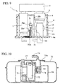
- FIG. 10 of the accompanying drawings schematically illustrates a fuel tank apparatus disclosed in Japanese Patent Application Laid-Open No. 9-112374.
- the apparatus comprises a fuel pump 71, a fuel filter 72 and a pressure regulator 73 contained in a unit base 74 that can be divided into upper and lower parts.
- the unit base 74 is mounted into a fuel tank 75 by way of an opening 75a thereof so that consequently the pump 71 and the other components are mounted into the tank 65.
- a chamber member 76 constituting a sub-tank is rigidly secured to the inside of the tank 75. More specifically, the unit base 74 is arranged in the chamber member 76. Additionally, a fuel flow path 77 is arranged within the unit base 74.
- the fuel sucked up by the pump 71 is made to flow to the fuel filter 72 and the pressure regulator 73 by way of the path 77 and then fed to the engine by way of a connection pipe 78.
- FIG. 10 shows an improved operational efficiency because the pump 71 and certain other components are provided as modules, those modules are rather bulky and particularly the overall configuration of the apparatus including the sub-tank consisting of the chamber member 76 is remarkably large.
- Such a large apparatus inevitably requires the use of a large fuel tank. Therefore, there is a strong demand for small and lightweight fuel feed apparatus.
- one or more than one filter members such as paper filters and/or synthetic resin filters are contained in the strainer in order to filter the fuel discharged from the fuel pump.
- the fuel passing through the filter can easily generate static electricity due to its friction with the filter materials.
- the fuel can give rise to turbulence before and after passing through the filter to cause friction between the synthetic resin case and fuel, which also consequently generates static electricity.
- Japanese Patent Application Laid-Open No. 8-232792 proposes an in-tank type fuel pump apparatus wherein grounding lead wires are connected to the fuel filter to allow the generated static electricity to flow to the ground.
- a lead wire is connected to each of the components housed in the tank. Then, the lead wires are electrically connected with the vehicle wire harness so that the components are grounded and prevented from becoming electrically charged.
- Japanese Patent Application Laid-Open No. 10-220315 proposes the use of a filter case made of an electrically conductive material so that the generated static electricity may be discharged into the fuel in it from the outer peripheral surface thereof.
- the above identified patent document also discloses a technique of connecting lead wires to the electrically conductive filter case at an end and to a grounding electrode outside of the fuel tank at the other end in order to allow the static electricity generated in the filter case to flow to the ground. If the fuel tank is made of metal, the lead wires are also connected to it so that the static electricity generated there may directly flow to the ground.
- fuel tanks are generally provided with a warning sensor comprising a thermistor for notifying the driver with the volume of fuel left in the fuel tank when the fuel in the tank falls below a certain threshold level.
- a warning sensor comprising a thermistor for notifying the driver with the volume of fuel left in the fuel tank when the fuel in the tank falls below a certain threshold level.
- electricity flows through such a thermistor at a very low rate and hence the thermistor generates heat to a small extent.
- the fuel cools the thermistor and hence its temperature would not rise. If, on the other hand, the fuel level falls to make the thermistor emerge from the fuel, the fuel no longer cools it and its temperature rises.
- the electric resistance of a thermistor changes as its temperature. Therefore, the volume of fuel left in the tank can be detected by detecting the change in the electric resistance of the thermistor.
- thermistors are popularly used as the above described sensors.
- lead wires connected to the thermistor are also arranged in the fuel tank so that the signal from the thermistor is received by way of the lead wires to detect the volume of fuel left in the tank.
- Another object of the invention is to provide a fuel feed apparatus that can be realized in a simplified manner by reducing the number of wiring steps of operation and also the number of parts of the apparatus.
- a fuel feed apparatus comprising a fuel pump for sucking fuel from a fuel tank and discharging it, a strainer for filtering the fuel discharged from said fuel pump, a pressure regulator for regulating the fuel feeding pressure, said fuel pump and at least either said strainer or said pressure regulator being arranged within said fuel tank, a sleeve-like reservoir arranged in said fuel tank and having an internal space for storing the fuel which said fuel pump sucks in, a holder fitted to an upper portion of said reservoir and holding said fuel pump and said strainer and a coupling member fitted to an upper portion of said fuel pump and also to an upper portion of said strainer for holding said fuel pump and said strainer.
- a fuel feed apparatus comprising a fuel pump for sucking fuel from a fuel tank and discharging it, a strainer for filtering the fuel discharged from said fuel pump, a pressure regulator for regulating the fuel feeding pressure, said fuel pump and at least either said strainer or said pressure regulator being arranged within said fuel tank, a sleeve-like reservoir arranged in said fuel tank and having an internal space for storing the fuel which said fuel pump sucks in, a holder fitted to an upper portion of said reservoir and holding said fuel pump and said pressure regulator and a coupling member fitted to an upper portion of said fuel pump and also to an upper portion of said pressure regulator for holding said fuel pump and said pressure regulator.
- the fuel pump and the strainer or the pressure regulator can be linked together simply by arranging a coupling member between them and to streamline the apparatus by reducing the size and weight thereof particularly in an upper area of the apparatus.
- the sleeve-like reservoir may be cylindrical or column-shaped.
- the internal and external dimensions of the reservoir are not subjected to particular limitations.
- the reservoir may have a rectangularly parallelepipedic profile or an oval profile.
- Said coupling member of a fuel feed apparatus may contain therein a fuel flow path for connecting said fuel pump with said strainer or said pressure regulator and said fuel flow path may be provided with a check valve for preventing fuel from flowing reversely.
- the coupling member not only operates to couple the related components but also provides a room for housing the check valve so that the internal space of the apparatus will be effectively and efficiently utilized to reduce the overall height of the apparatus.
- Said coupling member of a fuel feed apparatus may include a connecting section of said coupling member to be connected with said fuel pump is provided with an engaging section to be engaged with an upper portion of said fuel pump.
- the fuel returned from the pressure regulator may be fed back into the reservoir, then, all the fuel returned by the pressure regulator is put back into the reservoir so that all the fuel in the reservoir can be used without wasting and the engine can be fed with fuel on a highly stable basis.
- said reservoir may comprise a fuel in-take port having a labyrinth structure, with this arrangement, the fuel that has flown into the reservoir would not flow out easily as the labyrinth blocks any fuel trying to flow out.
- a fuel feed apparatus comprising a fuel pump for sucking fuel from a fuel tank and discharging it, a strainer for filtering the fuel discharged from said fuel pump, said fuel pump and said strainer being arranged within said fuel tank, a sensor for detecting the amount of the residual fuel in the fuel tank and a sensor holder made of an electrically conductive material and arranged in said fuel tank to hold said sensor, said sensor holder having a strainer-connecting section connected to said strainer and an earth-connecting section electrically connected to the grounding terminal of said sensor.
- the sensor holder can be commonly used as the grounding terminal of the strainer and also as that of the sensor to eliminate not only the grounding wire of the strainer but also the step of arranging the grounding wire of either the strainer or the sensor.
- both the number of parts and that of processing steps can be reduced in the process of building the apparatus.
- a thermistor may be used for said sensor, additionally, said sensor holder may be formed by using a metal wire having said strainer-connecting section formed at an end thereof and said earth-connecting section formed at the opposite end thereof.
- FIG. 1 is a schematic lateral view of an embodiment of fuel feed apparatus according to the invention and arranged in position.
- FIG. 2 is a partially exploded schematic perspective view of the embodiment of fuel feed apparatus according to the invention.
- FIG. 3 is a schematic lateral view of the embodiment of fuel feed apparatus according to the invention, illustrated partly in cross section.
- FIG. 4 is a schematic plan view of the embodiment of fuel feed apparatus according to the invention.
- the fuel feed apparatus 1 of this embodiment (hereinafter referred to simply as "apparatus") is adapted to operate as in-tank type gasoline feed apparatus to be used with a motor bicycle.
- the apparatus 1 is fitted to an opening 3 formed through the bottom 2a of a fuel tank 2 from below.
- it comprises a cup-shaped unit base 4 containing a fuel pump 5, a strainer 6 and a pressure regulator 7 along with other components to realize in the form of a module.
- the apparatus 1 purifies fuel 42, sucked up by the pump 5, by means of the strainer 6 and regulate the pressure of the fuel to a predetermined level by means of the pressure regulator 7 before feeding it to the engine by way of a fuel feed pipe 43.
- a flange 4a is formed as bottom plate at the bottom of unit base 4.
- the flange 4a is formed integrally with reservoir 4b operating as lateral wall from synthetic resin by molding.
- the apparatus 1 is oil-tightly secured to the tank 2 as it is fitted to the opening 3 by way of a packing 8.
- the fuel feed apparatus 1 according to the invention is a module that can be installed by simply fitting it to the tank 2 and hence can remarkably improve the efficiency of mounting operation.
- the inside of the unit base 4 of the apparatus 1 is empty and adapted to contain the pump 5 and other components and operate, at the same time, as a sub-tank 16.
- the unit base 4 functions as reservoir so that the fuel 42 sucked up by the pump 5 is temporarily stored in the unit base 4 in order to avoid any improper supply of fuel that can arise when the motor vehicle drives up a slope or is fiercely shaken.
- conventional sub-tanks comprise a plurality of components typically as shown in FIG. 10, that of apparatus 1 of the present invention comprises only a unit base 4.
- the apparatus 1 has a reduced number of components to consequently reduce the manufacturing cost thereof.
- a holder 9 is fitted to an upper portion of the reservoir 4b and operates as closure for sub-tank 16.
- the pump 5 and strainer 6 are held by the holder 9 and housed in the unit base 4.
- a fuel suction port 10 is arranged under the pump 5 to draw fuel 42 from the bottom of the sub-tank 16.
- the port 10 is provided with a filter 13 to make fuel 42 get rid of coarse pieces of dirt.
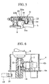
- FIG. 5 shows the configuration of the cover 11 and it is taken along line A-A in FIG. 4.
- the valve 20 contained in the cover 11 is mounted in a fuel flow path 21 and operates to prevent fuel from flowing reversely from the strainer 6 to the pump 5.
- the valve body 20a of the valve 20 is urged toward small diameter portion 21a of the path 20 by spring 20b.
- the pump 5 and the strainer 6 are held in position by the holder 9 and linked together by the cover 11 at an upper portion thereof.
- the pump 5 and the strainer 6 are linked together simply by arranging the cover 11 at an upper portion thereof in the apparatus 1.
- the cover 11 can be used to streamline the profile of the apparatus 1 in order to reduce both the size and the weight of the apparatus 1 particularly at the opposite lateral sides thereof.
- the cover 11 provides free space along its opposite lateral sides if compared with an apparatus of the same type that is covered by a cup-shaped cover.
- the cover 11 provides a space for installing the check valve 20 while it is operating as a coupling member. Therefore, the cover 11 not only cuts unnecessary space to reduce both the size and the weight of the apparatus 1 but also eliminates the space that may otherwise be required for the check valve to reduce the height of the apparatus.
- the connecting section for connecting the pump 5 and the cover 11 of the apparatus is designed to be space saving. More specifically, the pump 5 is provided at an upper portion thereof with a recess 22 for connecting itself to the cover 11. On the other hand, the connecting section of the cover 11 for connecting itself to the pump 5 is provided with a projection (engaging section) 23 to be engaged with the recess 22. Thus, the pump 5 and the cover 11 are linked together as the recess 22 and the projection 23 are held in mesh with each other. With this arrangement, the connecting section for connecting the pump 5 and the cover 11 is highly space saving to consequently reduce the height of the apparatus. It may be appreciated that alternatively the pump 5 may be provided with a projection while the cover 11 may be provided with a recess for connecting them.
- FIG. 6 is a schematic cross sectional partial view of the configuration of the pressure regulator fitting section. As shown in FIG. 6, the joint 12 is arranged between a lower portion of the strainer 6 and discharge port 14 projecting from the bottom of the unit base 4.
- the pressure regulator 7 is connected to a central portion of the joint 12.
- the apparatus 1 is used in a fuel feed system that may be a so-called return-less system
- the pressure regulator 7 is provided at the side of the fuel feed apparatus.
- the pressure regulator 7 is arranged within the sub-tank 16, and all the fuel returned from the pressure regulator 7 is fed back to the sub-tank 16.
- the fuel feed apparatus 1 of the present invention is free from the drawback of the above described known apparatus of returning the fuel 42 in the sub-tank 16 to the outside of the sub-tank 16 so that it can feed fuel to the engine on a highly stable basis.
- the discharge port 14 connected to a lower portion of the joint 12 communicates with a fuel feed port 15 arranged at the bottom of the unit base 4.
- a fuel feed port 15 arranged at the bottom of the unit base 4.
- FIG. 7 is a schematic lateral view of the apparatus 1 and FIG. 8 is a schematic plan view where the holder 9 and the cover 11 are removed from the apparatus 1.
- a motor bicycle may frequently be required to stand on the rear wheel and/or tilt sideways and supported by its prop stand while being fueled. Additionally, the center of gravity of a motor bicycle moves to the rear wheel side and it may prance on the rear wheel when accelerated. Still additionally, the front wheel side of a motor bicycle is higher than the rear side when it goes up a slope. Under any of these conditions, the engine requires to consume more fuel than ever.
- the port 17 of the apparatus 1 is arranged at a position that does not allow fuel to flow out when the body of the motor bicycle is tilted or at a position where the port 17 will face upward when the body of the motor bicycle is tilted. With this arrangement, fuel is prevented from flowing out of the sub-tank 16 even when the motor bicycle stands up on the rear wheel or when it prances.
- the opening 17a of the port 17 of this apparatus 1 is arranged at a position close to the front end of the body and opposite to the side where the prop stand is provided so that it may face upward when the front of the motor bicycle faces upward and hence fuel may be prevented from flowing out under any of the above identified conditions.
- While the location of the fuel port 17 is selected by taking both the situation where the motor bicycle is made to stand on the rear wheel and the situation where the motor bicycle is made to rest on its prop stand, it may alternatively be selected by dominantly taking either of the situations into consideration. If the situation where the motor bicycle is made to stand on the rear wheel is considered to be the dominant factor, the port 17 will be arranged at a position close to the front of the motor bicycle. If, on the other hand, the situation where the motor bicycle is tilted and made to rest on its prop stand is considered to be the dominant factor, the port 17 will be arranged at a position opposite to the side of the prop stand.
- the inside of the fuel intake port 17 has a labyrinth structure. More specifically, as shown in FIGS. 7 and 8, the port 17 is provided with a partition wall 18 extending peripherally from the opening 17a to the inside of the unit base 4 to produce a labyrinth 19.
- the wall 18 and the inner wall of the flange 4 define a labyrinth 19. Due to the provision of the labyrinth 19, the fuel flowing into the sub-tank 16 would not easily flow out from the tank. Therefore, the selected position of the port 17 and the provision of the labyrinth 19 minimize the risk of allowing fuel to flow out of the sub-tank 16.
- a thermistor 24 whose electrical resistance varies as a function of the ambient temperature is arranged inside the unit base 4 as warning sensor for notifying the driver with the volume of fuel left in the fuel tank.
- the internal temperature of a fuel tank rises as the amount of fuel stored in it decreases. Therefore, the thermistor 24 detects the volume of fuel left inside the tank by detecting the change in the ambient temperature and, when the fuel 42 in the fuel tank goes under a certain threshold level, it produces a warning by notifying the driver with the fact that fuel is running out.
- FIG. 9 is a schematic lateral view illustrating how the thermistor 24 is fitted and wired.
- a negative (grounding) lead wire 25a of the thermistor 24 is branched from a negative lead wire 25b of the pump 5.
- the thermistor 24 is secured to the unit base 4 by means of a thermistor arm (sensor holder) 26 made of an electrically conductive material such as a metal wire.
- a grounding wire connecting section 26a is formed on the arm 26 at a position close to the thermistor 24 and held in electric communication with the wire 25a.
- the arm 26 is connected to the wire 25b by way of the section 26a and the wire 25a.
- a strainer connecting section 26b is formed on the arm 26 at the side thereof opposite to the section 26a so that the arm 26 is held in contact with the outer periphery of the strainer 6 by means of the section 26b. Therefore, the strainer 26 is connected to the wire 25b by way of the arm 26 and hence grounded through the arm 26.
- the outer peripheral wall of the strainer 6 is made of metal or an electrically conductive resin material in order to allow any static electricity generated by the fuel passing through the filter member arranged inside and made of paper or resin to be discharged therefrom.
- the static electricity generated in the strainer 6 flows to the wire 25b by way of the arm 26 and the wire 25a.
- the arm 26 is utilized as grounding wire of the strainer 6 so that the thermistor 24 and the strainer 6 share a common grounding wire.
- the grounding wire of the strainer 6 which is otherwise need is omitted and hence only a single wiring operation is required for grounding the thermistor 24 and the strainer 6 to consequently reduce the number of parts and also the number of manufacturing steps.
- the above described arrangement can be used not only for a thermistor but also for a sensor that may alternatively be installed in the fuel tank with necessary wires. If such is the case, the holder of the sensor will be made of an electrically conductive material and grounded while it is held in contact with the strainer 6 in order to discharge static electricity by way of the holder.
- the pump 5 and the strainer 6 are mounted to the holder 9 in the above embodiment, it may alternatively be so arranged that the pressure regulator 7 is arranged upstream relative to the strainer 6 and the joint 12 is mounted onto the holder 9. Then, the holder holds the pump 5 and the pressure regulator 7 (joint 12) 9 and the cover 11. If such is the case, the strainer 6 should not necessarily be arranged within the fuel tank 2 as in the case of the pressure regulator 7 of the above embodiment.
- check valve 20 is contained in the cover 11 of the above described apparatus 1, it may alternatively be arranged downstream relative to the strainer 6. Then, the strainer 6 may be provided with a gas release hole.
- the apparatus 1 is fitted to the bottom side of the fuel tank 2 in the above description, it may be fitted to the top side of the fuel tank 2 like the known apparatus shown in FIG. 10.
- the flange 4a and the reservoir 4b are integrally formed and made to operate as unit base 4 in the above described apparatus 1, they should not necessarily be integrally formed and, alternatively, they may be formed separately from each other.
- the flange 4a may be omitted if the apparatus 1 is mounted to the top side of the fuel tank 2.
- the unit base 4 may take the form of a bottomed sleeve or, alternatively, it may take the form of a sleeve open both at the top and at the bottom and be fitted to the bottom of the fuel tank 2.
- the present invention is described above in terms of a fuel feed apparatus of a motor bicycle, the applicability of the present invention is by no means limited to motor bicycles and it can equally be used as fuel feed apparatus that is applicable to motor cars, carts for carrying caddy bags in golf courses, lawn mowers, industrial machines, portable generators and other machines comprising an internal combustion engine as source of motive power.
- the fuel to be used with a fuel feed apparatus according to the invention is not limited to gasoline but may alternatively be light oil or kerosene oil.
- the fuel pump and the strainer or the pressure regulator are held by a holder arranged at an upper portion of the reservoir and a coupling cover adapted to link the fuel pump and the strainer so that the fuel pump and the strainer or the pressure regulator can be linked together simply by arranging a coupling cover so streamline the apparatus and reduce both the size and the weight of the apparatus.
- the coupling cover not only operates for coupling different components but also provides a space for receiving the check valve in order to fully exploit the available space and reduce the height of the apparatus.
- the connecting section of the coupling cover to be connected to the fuel pump is provided with an engaging section to be engaged with the fuel pump
- the connecting section is highly space-saving and adapted to connect the fuel pump and the coupling cover within a reduced space in order to further reduce the height of the apparatus.
- the fuel returned from the pressure regulator may be fed back into the reservoir, then, all the fuel returned by the pressure regulator is put back into the reservoir so that all the fuel in the reservoir can be used without wasting and the engine can be fed with fuel on a highly stable basis. Still additionally, if the inside of the fuel in-take port is made to have a labyrinth structure, the effect of preventing fuel from flowing out through the fuel in-take port can be further enhanced.
- the thermistor operating as sensor for sensing the volume of fuel left in the fuel tank is held by a thermistor arm made of an electrically conductive material and the thermistor arm is electrically connected to the strainer at an end and grounded at the other end so that it can be used as the grounding terminal of the strainer. Then, the thermistor and the structure share a common grounding terminal to eliminate the grounding wire of the strainer. Accordingly, both the thermistor and the strainer can be grounded by means of a single common wire to reduce the number of parts and also that of manufacturing steps.
Landscapes
- Engineering & Computer Science (AREA)
- Chemical & Material Sciences (AREA)
- Combustion & Propulsion (AREA)
- Mechanical Engineering (AREA)
- General Engineering & Computer Science (AREA)
- Cooling, Air Intake And Gas Exhaust, And Fuel Tank Arrangements In Propulsion Units (AREA)
Applications Claiming Priority (4)
| Application Number | Priority Date | Filing Date | Title |
|---|---|---|---|
| JP11109528A JP2000297717A (ja) | 1999-04-16 | 1999-04-16 | 燃料供給装置 |
| JP10953099 | 1999-04-16 | ||
| JP10952899 | 1999-04-16 | ||
| JP10953099A JP4079546B2 (ja) | 1999-04-16 | 1999-04-16 | 燃料供給装置 |
Publications (3)
| Publication Number | Publication Date |
|---|---|
| EP1045132A2 true EP1045132A2 (fr) | 2000-10-18 |
| EP1045132A3 EP1045132A3 (fr) | 2001-03-07 |
| EP1045132B1 EP1045132B1 (fr) | 2005-12-14 |
Family
ID=26449269
Family Applications (1)
| Application Number | Title | Priority Date | Filing Date |
|---|---|---|---|
| EP20000108268 Expired - Lifetime EP1045132B1 (fr) | 1999-04-16 | 2000-04-14 | Appareil d'alimentation en carburant |
Country Status (3)
| Country | Link |
|---|---|
| EP (1) | EP1045132B1 (fr) |
| CN (1) | CN1195651C (fr) |
| TW (1) | TW493038B (fr) |
Cited By (2)
| Publication number | Priority date | Publication date | Assignee | Title |
|---|---|---|---|---|
| WO2003044357A1 (fr) * | 2001-11-20 | 2003-05-30 | Mitsubishi Denki Kabushiki Kaisha | Systeme d'alimentation en carburant pour vehicule |
| CN104154842A (zh) * | 2014-08-27 | 2014-11-19 | 吴中区横泾博尔机械厂 | 一种简易式主板元器件高度检测器 |
Families Citing this family (8)
| Publication number | Priority date | Publication date | Assignee | Title |
|---|---|---|---|---|
| US7117732B2 (en) * | 2003-12-01 | 2006-10-10 | Societe Bic | Fuel gauge for fuel cartridges |
| CN100373043C (zh) * | 2004-03-29 | 2008-03-05 | 三菱电机株式会社 | 燃油供给装置 |
| CN100486859C (zh) * | 2004-08-19 | 2009-05-13 | 光阳工业股份有限公司 | 喷射引擎摩托车的油箱 |
| JP4356897B2 (ja) * | 2005-06-07 | 2009-11-04 | 株式会社デンソー | 燃料供給装置 |
| US7237538B2 (en) * | 2005-09-09 | 2007-07-03 | Ti Automotive Fuel Systems Sas | Modular fuel delivery assembly |
| JP4888419B2 (ja) * | 2008-03-03 | 2012-02-29 | 三菱電機株式会社 | 車両用燃料供給装置 |
| JP5777878B2 (ja) * | 2010-12-24 | 2015-09-09 | 株式会社ミツバ | 燃料供給装置 |
| JP5818433B2 (ja) * | 2010-12-24 | 2015-11-18 | 株式会社ミツバ | 燃料供給装置 |
Citations (3)
| Publication number | Priority date | Publication date | Assignee | Title |
|---|---|---|---|---|
| JPH08232792A (ja) | 1994-12-28 | 1996-09-10 | Nippondenso Co Ltd | インタンク式燃料ポンプ装置 |
| JPH09112374A (ja) | 1995-10-20 | 1997-04-28 | Kurata:Kk | 燃料タンク装置 |
| JPH10220315A (ja) | 1997-02-07 | 1998-08-18 | Unisia Jecs Corp | 燃料供給装置 |
Family Cites Families (5)
| Publication number | Priority date | Publication date | Assignee | Title |
|---|---|---|---|---|
| DE4242242C2 (de) * | 1992-12-15 | 2003-04-30 | Bosch Gmbh Robert | Vorrichtung zum Versorgen der Brennkraftmaschine eines Kraftfahrzeuges mit in einem Vorratstank vorhandenem Kraftstoff |
| JP3323600B2 (ja) * | 1993-09-28 | 2002-09-09 | マツダ株式会社 | 燃料温度検出装置 |
| DE4444854C2 (de) * | 1994-12-16 | 2002-10-24 | Bosch Gmbh Robert | Förderaggregat |
| DE19508978C2 (de) * | 1995-03-13 | 1997-02-13 | Daimler Benz Ag | Kraftstofftank für Kraftfahrzeuge |
| US5647330A (en) * | 1996-07-25 | 1997-07-15 | General Motors Corporation | Fuel sender for motor vehicle |
-
2000
- 2000-04-06 TW TW89106292A patent/TW493038B/zh active
- 2000-04-14 EP EP20000108268 patent/EP1045132B1/fr not_active Expired - Lifetime
- 2000-04-14 CN CNB001065831A patent/CN1195651C/zh not_active Expired - Fee Related
Patent Citations (3)
| Publication number | Priority date | Publication date | Assignee | Title |
|---|---|---|---|---|
| JPH08232792A (ja) | 1994-12-28 | 1996-09-10 | Nippondenso Co Ltd | インタンク式燃料ポンプ装置 |
| JPH09112374A (ja) | 1995-10-20 | 1997-04-28 | Kurata:Kk | 燃料タンク装置 |
| JPH10220315A (ja) | 1997-02-07 | 1998-08-18 | Unisia Jecs Corp | 燃料供給装置 |
Cited By (2)
| Publication number | Priority date | Publication date | Assignee | Title |
|---|---|---|---|---|
| WO2003044357A1 (fr) * | 2001-11-20 | 2003-05-30 | Mitsubishi Denki Kabushiki Kaisha | Systeme d'alimentation en carburant pour vehicule |
| CN104154842A (zh) * | 2014-08-27 | 2014-11-19 | 吴中区横泾博尔机械厂 | 一种简易式主板元器件高度检测器 |
Also Published As
| Publication number | Publication date |
|---|---|
| EP1045132A3 (fr) | 2001-03-07 |
| CN1195651C (zh) | 2005-04-06 |
| CN1270899A (zh) | 2000-10-25 |
| TW493038B (en) | 2002-07-01 |
| EP1045132B1 (fr) | 2005-12-14 |
Similar Documents
| Publication | Publication Date | Title |
|---|---|---|
| US7451745B2 (en) | Fuel tank for motorcycle | |
| US6260543B1 (en) | Fuel delivery module with integrated filter | |
| US5649514A (en) | Fuel supply apparatus | |
| EP1043495B1 (fr) | Dispositif d'alimentation en carburant | |
| JP3846604B2 (ja) | 燃料供給装置 | |
| JP5414483B2 (ja) | 燃料供給装置 | |
| EP1045132B1 (fr) | Appareil d'alimentation en carburant | |
| JP3956867B2 (ja) | 燃料供給装置 | |
| JP3640001B2 (ja) | 燃料供給装置 | |
| EP1045133B1 (fr) | Appareil d'alimentation en carburant | |
| US20080295593A1 (en) | Fuel supply systems | |
| JP2010001761A (ja) | 燃料供給装置 | |
| CN101503985A (zh) | 泵组件 | |
| US20210115885A1 (en) | Fuel Supply Device | |
| US7268301B2 (en) | Lid of fuel tank | |
| EP1108883A2 (fr) | Système d'alimentation en carburant | |
| JP4442997B2 (ja) | 燃料供給装置 | |
| CA2570771A1 (fr) | Ensemble de pompe et de reservoir a carburant pour vehicule automobile | |
| JP3908941B2 (ja) | 燃料供給ユニット | |
| JP4079546B2 (ja) | 燃料供給装置 | |
| JP2000301958A (ja) | 燃料供給装置 | |
| US20060260696A1 (en) | Fuel delivery and vapor control system | |
| JP2000297717A (ja) | 燃料供給装置 | |
| JP7378919B2 (ja) | 燃料供給装置 | |
| JP5554055B2 (ja) | 燃料供給装置 |
Legal Events
| Date | Code | Title | Description |
|---|---|---|---|
| PUAI | Public reference made under article 153(3) epc to a published international application that has entered the european phase |
Free format text: ORIGINAL CODE: 0009012 |
|
| AK | Designated contracting states |
Kind code of ref document: A2 Designated state(s): FR IT |
|
| AX | Request for extension of the european patent |
Free format text: AL;LT;LV;MK;RO;SI |
|
| PUAL | Search report despatched |
Free format text: ORIGINAL CODE: 0009013 |
|
| AK | Designated contracting states |
Kind code of ref document: A3 Designated state(s): AT BE CH CY DE DK ES FI FR GB GR IE IT LI LU MC NL PT SE |
|
| AX | Request for extension of the european patent |
Free format text: AL;LT;LV;MK;RO;SI |
|
| 17P | Request for examination filed |
Effective date: 20010831 |
|
| AKX | Designation fees paid |
Free format text: FR IT |
|
| 17Q | First examination report despatched |
Effective date: 20040707 |
|
| REG | Reference to a national code |
Ref country code: DE Ref legal event code: 8566 |
|
| GRAP | Despatch of communication of intention to grant a patent |
Free format text: ORIGINAL CODE: EPIDOSNIGR1 |
|
| GRAS | Grant fee paid |
Free format text: ORIGINAL CODE: EPIDOSNIGR3 |
|
| GRAA | (expected) grant |
Free format text: ORIGINAL CODE: 0009210 |
|
| AK | Designated contracting states |
Kind code of ref document: B1 Designated state(s): FR IT |
|
| ET | Fr: translation filed | ||
| PLBE | No opposition filed within time limit |
Free format text: ORIGINAL CODE: 0009261 |
|
| STAA | Information on the status of an ep patent application or granted ep patent |
Free format text: STATUS: NO OPPOSITION FILED WITHIN TIME LIMIT |
|
| 26N | No opposition filed |
Effective date: 20060915 |
|
| PGFP | Annual fee paid to national office [announced via postgrant information from national office to epo] |
Ref country code: FR Payment date: 20080314 Year of fee payment: 9 |
|
| PGFP | Annual fee paid to national office [announced via postgrant information from national office to epo] |
Ref country code: IT Payment date: 20080422 Year of fee payment: 9 |
|
| REG | Reference to a national code |
Ref country code: FR Ref legal event code: ST Effective date: 20091231 |
|
| PG25 | Lapsed in a contracting state [announced via postgrant information from national office to epo] |
Ref country code: FR Free format text: LAPSE BECAUSE OF NON-PAYMENT OF DUE FEES Effective date: 20091222 |
|
| PG25 | Lapsed in a contracting state [announced via postgrant information from national office to epo] |
Ref country code: IT Free format text: LAPSE BECAUSE OF NON-PAYMENT OF DUE FEES Effective date: 20090414 |