EP1045215A2 - Procédé et dispositif pour le refroidissement d'un écoulement gazeux - Google Patents
Procédé et dispositif pour le refroidissement d'un écoulement gazeux Download PDFInfo
- Publication number
- EP1045215A2 EP1045215A2 EP00106673A EP00106673A EP1045215A2 EP 1045215 A2 EP1045215 A2 EP 1045215A2 EP 00106673 A EP00106673 A EP 00106673A EP 00106673 A EP00106673 A EP 00106673A EP 1045215 A2 EP1045215 A2 EP 1045215A2
- Authority
- EP
- European Patent Office
- Prior art keywords
- heat exchanger
- gas stream
- cooling
- fed
- conveyor
- Prior art date
- Legal status (The legal status is an assumption and is not a legal conclusion. Google has not performed a legal analysis and makes no representation as to the accuracy of the status listed.)
- Granted
Links
- 238000001816 cooling Methods 0.000 title claims abstract description 31
- 238000000034 method Methods 0.000 title claims abstract description 25
- 238000004140 cleaning Methods 0.000 claims description 6
- 239000002826 coolant Substances 0.000 claims description 6
- 239000000498 cooling water Substances 0.000 claims description 6
- 239000003507 refrigerant Substances 0.000 claims description 6
- 239000000126 substance Substances 0.000 claims description 6
- 238000001704 evaporation Methods 0.000 claims description 5
- 239000012267 brine Substances 0.000 claims description 2
- HPALAKNZSZLMCH-UHFFFAOYSA-M sodium;chloride;hydrate Chemical compound O.[Na+].[Cl-] HPALAKNZSZLMCH-UHFFFAOYSA-M 0.000 claims description 2
- 238000009833 condensation Methods 0.000 abstract description 2
- 239000007789 gas Substances 0.000 description 45
- IJGRMHOSHXDMSA-UHFFFAOYSA-N Atomic nitrogen Chemical compound N#N IJGRMHOSHXDMSA-UHFFFAOYSA-N 0.000 description 8
- 239000007788 liquid Substances 0.000 description 5
- 229910052757 nitrogen Inorganic materials 0.000 description 4
- 239000000463 material Substances 0.000 description 2
- VOPWNXZWBYDODV-UHFFFAOYSA-N Chlorodifluoromethane Chemical compound FC(F)Cl VOPWNXZWBYDODV-UHFFFAOYSA-N 0.000 description 1
- 239000012080 ambient air Substances 0.000 description 1
- 230000005494 condensation Effects 0.000 description 1
- 230000000694 effects Effects 0.000 description 1
- 238000005516 engineering process Methods 0.000 description 1
- 230000002349 favourable effect Effects 0.000 description 1
- 239000000203 mixture Substances 0.000 description 1
- 238000013021 overheating Methods 0.000 description 1
- 238000005086 pumping Methods 0.000 description 1
- 230000001105 regulatory effect Effects 0.000 description 1
- 239000007787 solid Substances 0.000 description 1
Images
Classifications
-
- F—MECHANICAL ENGINEERING; LIGHTING; HEATING; WEAPONS; BLASTING
- F28—HEAT EXCHANGE IN GENERAL
- F28D—HEAT-EXCHANGE APPARATUS, NOT PROVIDED FOR IN ANOTHER SUBCLASS, IN WHICH THE HEAT-EXCHANGE MEDIA DO NOT COME INTO DIRECT CONTACT
- F28D7/00—Heat-exchange apparatus having stationary tubular conduit assemblies for both heat-exchange media, the media being in contact with different sides of a conduit wall
- F28D7/0066—Multi-circuit heat-exchangers, e.g. integrating different heat exchange sections in the same unit or heat-exchangers for more than two fluids
-
- B—PERFORMING OPERATIONS; TRANSPORTING
- B01—PHYSICAL OR CHEMICAL PROCESSES OR APPARATUS IN GENERAL
- B01D—SEPARATION
- B01D5/00—Condensation of vapours; Recovering volatile solvents by condensation
- B01D5/0003—Condensation of vapours; Recovering volatile solvents by condensation by using heat-exchange surfaces for indirect contact between gases or vapours and the cooling medium
- B01D5/0009—Horizontal tubes
-
- B—PERFORMING OPERATIONS; TRANSPORTING
- B01—PHYSICAL OR CHEMICAL PROCESSES OR APPARATUS IN GENERAL
- B01D—SEPARATION
- B01D5/00—Condensation of vapours; Recovering volatile solvents by condensation
- B01D5/0033—Other features
- B01D5/0036—Multiple-effect condensation; Fractional condensation
-
- B—PERFORMING OPERATIONS; TRANSPORTING
- B01—PHYSICAL OR CHEMICAL PROCESSES OR APPARATUS IN GENERAL
- B01D—SEPARATION
- B01D53/00—Separation of gases or vapours; Recovering vapours of volatile solvents from gases; Chemical or biological purification of waste gases, e.g. engine exhaust gases, smoke, fumes, flue gases, aerosols
- B01D53/002—Separation of gases or vapours; Recovering vapours of volatile solvents from gases; Chemical or biological purification of waste gases, e.g. engine exhaust gases, smoke, fumes, flue gases, aerosols by condensation
-
- F—MECHANICAL ENGINEERING; LIGHTING; HEATING; WEAPONS; BLASTING
- F28—HEAT EXCHANGE IN GENERAL
- F28B—STEAM OR VAPOUR CONDENSERS
- F28B9/00—Auxiliary systems, arrangements, or devices
- F28B9/08—Auxiliary systems, arrangements, or devices for collecting and removing condensate
-
- F—MECHANICAL ENGINEERING; LIGHTING; HEATING; WEAPONS; BLASTING
- F28—HEAT EXCHANGE IN GENERAL
- F28D—HEAT-EXCHANGE APPARATUS, NOT PROVIDED FOR IN ANOTHER SUBCLASS, IN WHICH THE HEAT-EXCHANGE MEDIA DO NOT COME INTO DIRECT CONTACT
- F28D7/00—Heat-exchange apparatus having stationary tubular conduit assemblies for both heat-exchange media, the media being in contact with different sides of a conduit wall
- F28D7/0066—Multi-circuit heat-exchangers, e.g. integrating different heat exchange sections in the same unit or heat-exchangers for more than two fluids
- F28D7/0075—Multi-circuit heat-exchangers, e.g. integrating different heat exchange sections in the same unit or heat-exchangers for more than two fluids with particular circuits for the same heat exchange medium, e.g. with the same heat exchange medium flowing through sections having different heat exchange capacities or for heating or cooling the same heat exchange medium at different temperatures
-
- F—MECHANICAL ENGINEERING; LIGHTING; HEATING; WEAPONS; BLASTING
- F28—HEAT EXCHANGE IN GENERAL
- F28D—HEAT-EXCHANGE APPARATUS, NOT PROVIDED FOR IN ANOTHER SUBCLASS, IN WHICH THE HEAT-EXCHANGE MEDIA DO NOT COME INTO DIRECT CONTACT
- F28D21/00—Heat-exchange apparatus not covered by any of the groups F28D1/00 - F28D20/00
- F28D2021/0019—Other heat exchangers for particular applications; Heat exchange systems not otherwise provided for
- F28D2021/0075—Other heat exchangers for particular applications; Heat exchange systems not otherwise provided for for syngas or cracked gas cooling systems
Definitions
- the invention relates to a method for cooling a gas stream, in which the gas flow is fed to a heat exchanger and a conveyor as well as a device.
- the inlet temperature that means the Suction temperature of the conveyor
- the Suction temperature of the conveyor be as low as possible to the To protect the conveyor on the one hand and the other Increase delivery capacity.
- the operation of the conveyor means that Temperature of the gas streams increased again.
- the above-mentioned device has the disadvantages that two Heat exchangers are used, reducing the cost of the entire plant are relatively high.
- the invention has for its object the disadvantages of the aforementioned To overcome the prior art and a method and a device create where the inevitable in the promotion of gas flows incidence of heat on technically simple and therefore inexpensive Way is compensated.
- the object underlying the invention is achieved by a method for Cooling of a gas stream solved, in which the gas stream one Heat exchanger and a conveyor is supplied and which thereby is characterized in that the gas flow is initially at least a first part of the Heat exchanger is supplied and cooled in it and then the Conveyor is fed and that after that from the conveyor coming gas flow at least a second part of the heat exchanger is fed and cooled therein.
- gas stream includes all gaseous material streams, which also contains other components, such as solid substances, liquid ones May contain substances or vapors.
- condensate formed in the Heat exchanger at at least one condensate drain of the first part and / or the second part of the heat exchanger is withdrawn.
- a partial flow of 0% to 100 is in the intermediate circuit %, based on the total volume flow of the gas stream. It is at this embodiment of the method of particular advantage that with the help of the intermediate circuit additionally a volume flow control according to desired procedure can be done.
- the cooling and at least partial Condensation of the substances contained in the material flow enables a technically and / or energetically favorable operation of downstream cleaning devices, preferably Cryocondensation plants.
- the from the second part of the Heat exchanger coming gas stream is fed to a cooling chamber wherein parts or substances in the cooling chamber are cooled.
- cooling water, cooling brine or an evaporating refrigerant for cooling the gas stream is supplied to the heat exchanger as the cooling medium.
- Storage tanks or chillers or cooling towers for cooling water can serve as the source of the cooling medium.
- the cooling medium and the source are selected in accordance with the desired cooling effect and according to the conditions at the place where the method is used. With the help of cooling water, for example, a cooling temperature of approx. 20 ° C to 30 ° C is reached. As a rule, lower temperatures of approx. ⁇ 40 ° C to approx. 0 ° C can be achieved by using a chiller. Even lower temperatures can be guaranteed by the very high cooling capacity of systems with an evaporating refrigerant. Under the term evaporating refrigerants "are to be understood in particular as organic substances or their mixtures, such as Frigen, or cryogenic liquid or supercritical gases, such as liquid nitrogen.
- the object underlying the invention is further achieved by a device solved for cooling a gas stream, which a conveyor and a Has heat exchanger, and which is characterized in that the Heat exchanger has at least two parts that at least a first part of the heat exchanger, an input line for supplying the gas stream and a first connecting line for guiding the gas flow from the first part of the heat exchanger and feed into the conveyor, and that the gas flow from the conveyor via a second connecting line is led away and at least a second part of the heat exchanger is fed.
- the second connecting line is via a control or Control valve in connection with a third connecting line for return of at least a partial stream of the coming from the conveyor Gas flow in the first part of the heat exchanger.
- Control or control fittings are, for example, valves, slides, flaps or ball valves.
- a 3-way valve is used here, which regulates the partial flow in the intermediate circuit from 0% to 100% is made possible. It can be preferred instead of the technically relatively complex and expensive 3-way valve or several individual fittings, e.g. Single valves, which are used are technically simpler and cheaper.
- the partial flow in the intermediate circuit can reach values of approx. 30% to approx. 100% with a single valve in the third connection line or to values of approx. 0 % to approx. 70% with a single valve in the second connection line can be set.
- the conveyor is a compressor, a blower or a pump.
- the device according to the invention is preferably used for Carrying out a method according to claim 1.
- a volume flow of approx. 20,000 m 3 / h of a gas from a cooling chamber, which essentially consists of nitrogen, is, with the aid of the method according to the invention, through a heat exchanger with two parts with an inlet temperature of approx. 80 ° C. and a pressure of approx. 50 mbar brought to an outlet temperature of about 30 ° C and a pressure of about 250 mbar and returned to the cooling chamber for cooling parts.
- the hot gas is sucked through a first part of the heat exchanger, for example a first tube bundle, with the aid of a blower, a pressure-maintaining device arranged on the suction side of the blower, for example a pressure reducing valve and an overflow valve, keeping the blower's suction pressure constant at about 20 to 30 mbar.
- a pressure-maintaining device arranged on the suction side of the blower, for example a pressure reducing valve and an overflow valve, keeping the blower's suction pressure constant at about 20 to 30 mbar.
- the circuit pressure on the pressure side of the fan is limited to approx. 350 to 400 mbar, for example by an overflow valve. If the circuit pressure rises above this value, excess gas flows out here and is discharged, for example to the outside.
- the main gas flow flows through a second part of the heat exchanger, for example a second tube bundle, in order to essentially dissipate the heat introduced into the circuit by the blower.
- the gas temperature reached at the outlet of this second part of the heat exchanger depends on the cooling capacity of the refrigerant.
- a temperature of the gas of approx. 30 ° C is reached here.
- the cooled gas is then returned to the cooling chamber.
- the amount of gas not required in the cooling chamber is returned to the suction side of the system through a fitting and intermediate line connected in parallel with the fan and the first part of the heat exchanger.
- the volume flow of the gas can be regulated.
- a slight overpressure of the gas in the system ensures that ambient air cannot enter the system if there is a slight leakage.
- the first and second part of the heat exchanger are connected in series. Compared to the prior art method described above with two heat exchangers, the heat exchanger costs could be reduced by approximately 30% with the method according to the invention and the technically relatively easy to implement system with comparable cooling capacity.
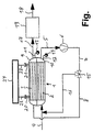
- the figure shows the heat exchanger according to the invention and the conveyor.
- the heat exchanger 1 has two parts 2, 3.
- the first part 2 of the Heat exchanger 1 is supplied via an input line 4, the gas stream.
- the gas flow from the first part 2 is connected via a first connecting line 5 of the heat exchanger 1 sucked by a conveyor 6 and the gas flow is from the conveyor 6 via second connecting lines 7,8 led away and fed to the second part 3 of the heat exchanger 1.
- in the Heat exchanger 1 resulting condensate is here at the head end 9, 10 of the first and second parts 2, 3 of the heat exchanger 1, e.g. via lines 11, 12 through siphon systems 13, 14.
- the heat exchanger 1 can lying, standing or preferably inclined and can be used for certain applications are advantageous in the direction of flow of the gas stream be inclined so that the condensate easily towards the head ends 9,10 of the corresponding part 2.3 of the heat exchanger 1 can flow off.
- Use cases can also include at least one consumple drain 11, 12, 13, 14 elsewhere or points of the heat exchanger 1 are arranged.
- Arises in other applications no or only a very small amount of Condensate, so for these processes to a condensate drain 11, 12, 13, 14th can also be dispensed with entirely.
- To regulate the volume flow of the exhaust gas can, a part of the exhaust gas flow via a conveyor 6 downstream bypass system 15, 16 in the first part 2 of the Heat exchanger 1 are recycled.
- the Heat exchanger 1 is connected via connecting pieces 20, 21 and Lines 22, 23 an evaporating cooling medium, preferably a cryogenic Gas such as liquid nitrogen, added or removed.
- the lines 22, 23 are connected to a source 24 for the cooling medium, e.g. Liquid nitrogen tank, connected.
Landscapes
- Engineering & Computer Science (AREA)
- Chemical & Material Sciences (AREA)
- Mechanical Engineering (AREA)
- General Engineering & Computer Science (AREA)
- Chemical Kinetics & Catalysis (AREA)
- Physics & Mathematics (AREA)
- Thermal Sciences (AREA)
- Analytical Chemistry (AREA)
- General Chemical & Material Sciences (AREA)
- Oil, Petroleum & Natural Gas (AREA)
- Separation By Low-Temperature Treatments (AREA)
- Sampling And Sample Adjustment (AREA)
Applications Claiming Priority (2)
| Application Number | Priority Date | Filing Date | Title |
|---|---|---|---|
| DE19917115A DE19917115A1 (de) | 1999-04-15 | 1999-04-15 | Verfahren und Vorrichtung zur Kühlung eines Gasstroms |
| DE19917115 | 1999-04-15 |
Publications (3)
| Publication Number | Publication Date |
|---|---|
| EP1045215A2 true EP1045215A2 (fr) | 2000-10-18 |
| EP1045215A3 EP1045215A3 (fr) | 2001-03-28 |
| EP1045215B1 EP1045215B1 (fr) | 2004-11-10 |
Family
ID=7904719
Family Applications (1)
| Application Number | Title | Priority Date | Filing Date |
|---|---|---|---|
| EP00106673A Expired - Lifetime EP1045215B1 (fr) | 1999-04-15 | 2000-03-29 | Procédé et dispositif pour le refroidissement d'un écoulement gazeux |
Country Status (3)
| Country | Link |
|---|---|
| EP (1) | EP1045215B1 (fr) |
| AT (1) | ATE282184T1 (fr) |
| DE (2) | DE19917115A1 (fr) |
Cited By (7)
| Publication number | Priority date | Publication date | Assignee | Title |
|---|---|---|---|---|
| WO2008055804A1 (fr) * | 2006-11-10 | 2008-05-15 | Air Liquide Deutschland Gmbh | Procédé et dispositif pour la purification de gaz au moyen de la condensation partielle et procédé pour actionner le dispositif |
| EP1602401B2 (fr) † | 2004-06-01 | 2017-04-12 | Messer Group GmbH | Procédé et dispositif de condensation partielle contenant peu d'aerosols |
| WO2017157587A1 (fr) * | 2016-03-17 | 2017-09-21 | Bayerische Motoren Werke Aktiengesellschaft | Échangeur de chaleur et système de pile à combustible |
| EP3285036A1 (fr) * | 2016-08-14 | 2018-02-21 | Dallmann engineering & Service | Module d'échangeur de chaleur pour matériau en vrac |
| DE102017007031B3 (de) * | 2017-07-25 | 2018-12-20 | Messer Group Gmbh | Vorrichtung und Verfahren zum Abscheiden von Dämpfen aus einem Gasstrom |
| WO2020173922A1 (fr) * | 2019-02-27 | 2020-09-03 | Hydrogenious Lohc Technologies Gmbh | Procédé et appareil de séparation permettant de séparer un mélange de milieux ainsi que procédé et agencement permettant de produire de l'hydrogène |
| CN119838238A (zh) * | 2023-10-18 | 2025-04-18 | 中国石油化工股份有限公司 | 用于连续蒸馏的热耦合换热设备和聚烯烃催化剂母液的连续蒸馏方法 |
Families Citing this family (2)
| Publication number | Priority date | Publication date | Assignee | Title |
|---|---|---|---|---|
| CN112683078B (zh) * | 2020-12-04 | 2022-07-29 | 上海天汉环境资源有限公司 | 一种蒸发釜夹套蒸汽冷凝水循环利用的装置 |
| DE102022000164B4 (de) * | 2022-01-18 | 2026-03-12 | Messer Se & Co. Kgaa | Verfahren und Vorrichtung zum Abscheiden eines Stoffes aus einem Trägergasstrom durch Partialkondensation |
Family Cites Families (1)
| Publication number | Priority date | Publication date | Assignee | Title |
|---|---|---|---|---|
| DE2229757A1 (de) * | 1972-06-19 | 1974-01-24 | Gulf Oil Corp | Mehrstufige dampfkondensiervorrichtung |
-
1999
- 1999-04-15 DE DE19917115A patent/DE19917115A1/de not_active Ceased
-
2000
- 2000-03-29 DE DE50008559T patent/DE50008559D1/de not_active Expired - Lifetime
- 2000-03-29 AT AT00106673T patent/ATE282184T1/de not_active IP Right Cessation
- 2000-03-29 EP EP00106673A patent/EP1045215B1/fr not_active Expired - Lifetime
Cited By (13)
| Publication number | Priority date | Publication date | Assignee | Title |
|---|---|---|---|---|
| EP1602401B2 (fr) † | 2004-06-01 | 2017-04-12 | Messer Group GmbH | Procédé et dispositif de condensation partielle contenant peu d'aerosols |
| US9089808B2 (en) | 2006-11-10 | 2015-07-28 | L'Air Liquide Société Anonyme Pour L'Étude Et L'Exploitation Des Procedes Georges Claude | Method and device for gas purification by means of partial condensation, and method for operating the device |
| WO2008055804A1 (fr) * | 2006-11-10 | 2008-05-15 | Air Liquide Deutschland Gmbh | Procédé et dispositif pour la purification de gaz au moyen de la condensation partielle et procédé pour actionner le dispositif |
| US10811703B2 (en) | 2016-03-17 | 2020-10-20 | Bayerische Motoren Werke Aktiengesellschaft | Heat exchanger and fuel cell system |
| WO2017157587A1 (fr) * | 2016-03-17 | 2017-09-21 | Bayerische Motoren Werke Aktiengesellschaft | Échangeur de chaleur et système de pile à combustible |
| CN108701845A (zh) * | 2016-03-17 | 2018-10-23 | 宝马股份公司 | 热交换器和燃料电池系统 |
| CN108701845B (zh) * | 2016-03-17 | 2021-09-07 | 宝马股份公司 | 热交换器和燃料电池系统 |
| EP3285036A1 (fr) * | 2016-08-14 | 2018-02-21 | Dallmann engineering & Service | Module d'échangeur de chaleur pour matériau en vrac |
| DE102017007031B3 (de) * | 2017-07-25 | 2018-12-20 | Messer Group Gmbh | Vorrichtung und Verfahren zum Abscheiden von Dämpfen aus einem Gasstrom |
| CN113165869A (zh) * | 2019-02-27 | 2021-07-23 | 海德鲁基尼斯Lohc技术有限公司 | 用于分离介质混合物的方法和分离设备 |
| WO2020173922A1 (fr) * | 2019-02-27 | 2020-09-03 | Hydrogenious Lohc Technologies Gmbh | Procédé et appareil de séparation permettant de séparer un mélange de milieux ainsi que procédé et agencement permettant de produire de l'hydrogène |
| CN113165869B (zh) * | 2019-02-27 | 2024-03-26 | 海德鲁基尼斯Lohc技术有限公司 | 用于分离介质混合物的方法和分离设备,以及用于提供氢的方法和布置结构 |
| CN119838238A (zh) * | 2023-10-18 | 2025-04-18 | 中国石油化工股份有限公司 | 用于连续蒸馏的热耦合换热设备和聚烯烃催化剂母液的连续蒸馏方法 |
Also Published As
| Publication number | Publication date |
|---|---|
| DE50008559D1 (de) | 2004-12-16 |
| EP1045215A3 (fr) | 2001-03-28 |
| DE19917115A1 (de) | 2000-10-19 |
| EP1045215B1 (fr) | 2004-11-10 |
| ATE282184T1 (de) | 2004-11-15 |
Similar Documents
| Publication | Publication Date | Title |
|---|---|---|
| EP1045215B1 (fr) | Procédé et dispositif pour le refroidissement d'un écoulement gazeux | |
| CH677397A5 (fr) | ||
| DE1941553C3 (de) | Schmiervorrichtung für den Verdichter einer Kühlanlage | |
| DE10358015A1 (de) | Eindampfanlage | |
| DE69400794T2 (de) | Gaskompressionsverfahren und Vorrichtung | |
| DE1717080A1 (de) | Verfahren zur Gewinnung von reinem Wasser aus Seewasser und anderen Loesungen durch Entspannungsverdampfung und Kondensation | |
| EP0839560A2 (fr) | Procédé et dispositif d'épuration de gaz avec des échangeurs de chaleur | |
| DE10230610A1 (de) | Verfahren und Vorrichtung zur Verhinderung von Ablagerungen in Dampfsystemen | |
| DE1501101C3 (de) | Vorrichtung zum Erzeugen von Kälte und/oder zum Verflüssigen von Gasen | |
| DE1940052A1 (de) | Verfahren zum Betrieb eines Trockenkuehlturmes bei hohen Lufttemperaturen | |
| DE2747601C2 (de) | Verfahren zur Kühlung eines Brennelement-Transportbehälters | |
| DE4313573A1 (de) | Verringerung der Kondensation von Wasserdampf und Austreiben von Kondensat während der Kompression von Luft | |
| DE102021105999B4 (de) | Verfahren und Vorrichtung zur Rückverflüssigung von BOG | |
| DE10155985A1 (de) | Verfahren und Vorrichtung zum Destillieren von Wasser aus Meerwasser, Brackwasser oder anderen verunreinigten Wässern | |
| DE3001995C2 (fr) | ||
| DE69407642T2 (de) | Kühlgerät | |
| EP1433508A1 (fr) | Systeme d'extraction a fonctionnement continu et a circuit unique permettant l'extraction de co 2? de matieres premieres vegetales | |
| DE4243687C1 (de) | Vakuumanlage, insbesondere für die Sekundärmetallurgie | |
| DE301941C (fr) | ||
| DE2153651C3 (de) | Heißgasabtaueinrichtung für Kälteanlagen | |
| DE102020004275A1 (de) | Trocknungsvorrichtung mit Kühlelement für landwirtschaftliche Produkte und Verfahren zum Betrieb der Trocknungsvorrichtung | |
| EP0503299B1 (fr) | Procédé et appareil pour la congélation de fluides dans les tuyaux | |
| EP1030135A1 (fr) | Procédé et dispositif pour le refroidissement controlée utilisant l'evaporation d'azote liquide | |
| DE102021001650B4 (de) | Verfahren und Vorrichtung zur Rückverflüssigung von BOG | |
| DE164680C (fr) |
Legal Events
| Date | Code | Title | Description |
|---|---|---|---|
| PUAI | Public reference made under article 153(3) epc to a published international application that has entered the european phase |
Free format text: ORIGINAL CODE: 0009012 |
|
| AK | Designated contracting states |
Kind code of ref document: A2 Designated state(s): AT BE CH CY DE DK ES FI FR GB GR IE IT LI LU MC NL PT SE |
|
| AX | Request for extension of the european patent |
Free format text: AL;LT;LV;MK;RO;SI |
|
| PUAL | Search report despatched |
Free format text: ORIGINAL CODE: 0009013 |
|
| RIC1 | Information provided on ipc code assigned before grant |
Free format text: 7F 25J 3/00 A, 7B 01D 5/00 B, 7B 01D 53/00 B, 7F 24F 3/14 B |
|
| AK | Designated contracting states |
Kind code of ref document: A3 Designated state(s): AT BE CH CY DE DK ES FI FR GB GR IE IT LI LU MC NL PT SE |
|
| AX | Request for extension of the european patent |
Free format text: AL;LT;LV;MK;RO;SI |
|
| 17P | Request for examination filed |
Effective date: 20010928 |
|
| AKX | Designation fees paid |
Free format text: AT BE CH CY DE DK ES FI FR GB GR IE IT LI LU MC NL PT SE |
|
| RAP1 | Party data changed (applicant data changed or rights of an application transferred) |
Owner name: MESSER GRIESHEIM GMBH |
|
| 17Q | First examination report despatched |
Effective date: 20030422 |
|
| GRAP | Despatch of communication of intention to grant a patent |
Free format text: ORIGINAL CODE: EPIDOSNIGR1 |
|
| GRAS | Grant fee paid |
Free format text: ORIGINAL CODE: EPIDOSNIGR3 |
|
| GRAA | (expected) grant |
Free format text: ORIGINAL CODE: 0009210 |
|
| AK | Designated contracting states |
Kind code of ref document: B1 Designated state(s): AT BE CH CY DE DK ES FI FR GB GR IE IT LI LU MC NL PT SE |
|
| PG25 | Lapsed in a contracting state [announced via postgrant information from national office to epo] |
Ref country code: IT Free format text: LAPSE BECAUSE OF FAILURE TO SUBMIT A TRANSLATION OF THE DESCRIPTION OR TO PAY THE FEE WITHIN THE PRE;WARNING: LAPSES OF ITALIAN PATENTS WITH EFFECTIVE DATE BEFORE 2007 MAY HAVE OCCURRED AT ANY TIME BEFORE 2007. THE CORRECT EFFECTIVE DATE MAY BE DIFFERENT FROM THE ONE RECORDED.SCRIBED TIME-LIMIT Effective date: 20041110 Ref country code: IE Free format text: LAPSE BECAUSE OF FAILURE TO SUBMIT A TRANSLATION OF THE DESCRIPTION OR TO PAY THE FEE WITHIN THE PRESCRIBED TIME-LIMIT Effective date: 20041110 Ref country code: FI Free format text: LAPSE BECAUSE OF FAILURE TO SUBMIT A TRANSLATION OF THE DESCRIPTION OR TO PAY THE FEE WITHIN THE PRESCRIBED TIME-LIMIT Effective date: 20041110 Ref country code: FR Free format text: LAPSE BECAUSE OF NON-PAYMENT OF DUE FEES Effective date: 20041110 Ref country code: NL Free format text: LAPSE BECAUSE OF FAILURE TO SUBMIT A TRANSLATION OF THE DESCRIPTION OR TO PAY THE FEE WITHIN THE PRESCRIBED TIME-LIMIT Effective date: 20041110 |
|
| REG | Reference to a national code |
Ref country code: GB Ref legal event code: FG4D Free format text: NOT ENGLISH |
|
| REG | Reference to a national code |
Ref country code: CH Ref legal event code: EP |
|
| REG | Reference to a national code |
Ref country code: IE Ref legal event code: FG4D Free format text: GERMAN |
|
| REF | Corresponds to: |
Ref document number: 50008559 Country of ref document: DE Date of ref document: 20041216 Kind code of ref document: P |
|
| PG25 | Lapsed in a contracting state [announced via postgrant information from national office to epo] |
Ref country code: DK Free format text: LAPSE BECAUSE OF FAILURE TO SUBMIT A TRANSLATION OF THE DESCRIPTION OR TO PAY THE FEE WITHIN THE PRESCRIBED TIME-LIMIT Effective date: 20050210 Ref country code: SE Free format text: LAPSE BECAUSE OF FAILURE TO SUBMIT A TRANSLATION OF THE DESCRIPTION OR TO PAY THE FEE WITHIN THE PRESCRIBED TIME-LIMIT Effective date: 20050210 Ref country code: GR Free format text: LAPSE BECAUSE OF FAILURE TO SUBMIT A TRANSLATION OF THE DESCRIPTION OR TO PAY THE FEE WITHIN THE PRESCRIBED TIME-LIMIT Effective date: 20050210 |
|
| PG25 | Lapsed in a contracting state [announced via postgrant information from national office to epo] |
Ref country code: ES Free format text: LAPSE BECAUSE OF FAILURE TO SUBMIT A TRANSLATION OF THE DESCRIPTION OR TO PAY THE FEE WITHIN THE PRESCRIBED TIME-LIMIT Effective date: 20050221 |
|
| RAP2 | Party data changed (patent owner data changed or rights of a patent transferred) |
Owner name: AIR LIQUIDE DEUTSCHLAND GMBH |
|
| RAP2 | Party data changed (patent owner data changed or rights of a patent transferred) |
Owner name: AIR LIQUIDE DEUTSCHLAND GMBH |
|
| GBT | Gb: translation of ep patent filed (gb section 77(6)(a)/1977) |
Effective date: 20050302 |
|
| PG25 | Lapsed in a contracting state [announced via postgrant information from national office to epo] |
Ref country code: LU Free format text: LAPSE BECAUSE OF NON-PAYMENT OF DUE FEES Effective date: 20050329 Ref country code: CY Free format text: LAPSE BECAUSE OF FAILURE TO SUBMIT A TRANSLATION OF THE DESCRIPTION OR TO PAY THE FEE WITHIN THE PRESCRIBED TIME-LIMIT Effective date: 20050329 Ref country code: AT Free format text: LAPSE BECAUSE OF NON-PAYMENT OF DUE FEES Effective date: 20050329 |
|
| PG25 | Lapsed in a contracting state [announced via postgrant information from national office to epo] |
Ref country code: BE Free format text: LAPSE BECAUSE OF NON-PAYMENT OF DUE FEES Effective date: 20050331 Ref country code: MC Free format text: LAPSE BECAUSE OF NON-PAYMENT OF DUE FEES Effective date: 20050331 |
|
| NLT2 | Nl: modifications (of names), taken from the european patent patent bulletin |
Owner name: AIR LIQUIDE DEUTSCHLAND GMBH |
|
| NLV1 | Nl: lapsed or annulled due to failure to fulfill the requirements of art. 29p and 29m of the patents act | ||
| RAP2 | Party data changed (patent owner data changed or rights of a patent transferred) |
Owner name: AIR LIQUIDE DEUTSCHLAND GMBH |
|
| REG | Reference to a national code |
Ref country code: IE Ref legal event code: FD4D |
|
| PLBE | No opposition filed within time limit |
Free format text: ORIGINAL CODE: 0009261 |
|
| STAA | Information on the status of an ep patent application or granted ep patent |
Free format text: STATUS: NO OPPOSITION FILED WITHIN TIME LIMIT |
|
| BERE | Be: lapsed |
Owner name: MESSER GRIESHEIM G.M.B.H. Effective date: 20050331 |
|
| 26N | No opposition filed |
Effective date: 20050811 |
|
| EN | Fr: translation not filed | ||
| EN | Fr: translation not filed | ||
| BERE | Be: lapsed |
Owner name: *MESSER GRIESHEIM G.M.B.H. Effective date: 20050331 |
|
| PG25 | Lapsed in a contracting state [announced via postgrant information from national office to epo] |
Ref country code: PT Free format text: LAPSE BECAUSE OF NON-PAYMENT OF DUE FEES Effective date: 20050410 |
|
| PGFP | Annual fee paid to national office [announced via postgrant information from national office to epo] |
Ref country code: CH Payment date: 20080313 Year of fee payment: 9 |
|
| REG | Reference to a national code |
Ref country code: CH Ref legal event code: PL |
|
| PG25 | Lapsed in a contracting state [announced via postgrant information from national office to epo] |
Ref country code: LI Free format text: LAPSE BECAUSE OF NON-PAYMENT OF DUE FEES Effective date: 20090331 Ref country code: CH Free format text: LAPSE BECAUSE OF NON-PAYMENT OF DUE FEES Effective date: 20090331 |
|
| PGFP | Annual fee paid to national office [announced via postgrant information from national office to epo] |
Ref country code: GB Payment date: 20160321 Year of fee payment: 17 |
|
| GBPC | Gb: european patent ceased through non-payment of renewal fee |
Effective date: 20170329 |
|
| PG25 | Lapsed in a contracting state [announced via postgrant information from national office to epo] |
Ref country code: GB Free format text: LAPSE BECAUSE OF NON-PAYMENT OF DUE FEES Effective date: 20170329 |
|
| PGFP | Annual fee paid to national office [announced via postgrant information from national office to epo] |
Ref country code: DE Payment date: 20190225 Year of fee payment: 20 |
|
| REG | Reference to a national code |
Ref country code: DE Ref legal event code: R071 Ref document number: 50008559 Country of ref document: DE |