EP1045332A2 - Kassette für Karten - Google Patents
Kassette für Karten Download PDFInfo
- Publication number
- EP1045332A2 EP1045332A2 EP00108286A EP00108286A EP1045332A2 EP 1045332 A2 EP1045332 A2 EP 1045332A2 EP 00108286 A EP00108286 A EP 00108286A EP 00108286 A EP00108286 A EP 00108286A EP 1045332 A2 EP1045332 A2 EP 1045332A2
- Authority
- EP
- European Patent Office
- Prior art keywords
- card
- pair
- cassette
- shutter
- card cassette
- Prior art date
- Legal status (The legal status is an assumption and is not a legal conclusion. Google has not performed a legal analysis and makes no representation as to the accuracy of the status listed.)
- Granted
Links
Images



Classifications
-
- G—PHYSICS
- G06—COMPUTING OR CALCULATING; COUNTING
- G06K—GRAPHICAL DATA READING; PRESENTATION OF DATA; RECORD CARRIERS; HANDLING RECORD CARRIERS
- G06K13/00—Conveying record carriers from one station to another, e.g. from stack to punching mechanism
- G06K13/02—Conveying record carriers from one station to another, e.g. from stack to punching mechanism the record carrier having longitudinal dimension comparable with transverse dimension, e.g. punched card
- G06K13/08—Feeding or discharging cards
- G06K13/14—Card magazines, e.g. pocket, hopper
Definitions
- the present invention relates to a card cassette to be attached to a card producing apparatus.
- card producing apparatus In recent years, more and more card producing apparatus have been put into actual use. In fact, these card producing apparatus are used with unattended contracting machines set by a loan company, capable of printing and producing membership cards (having attached thereon magnetic stripes). In practice, a card producing apparatus is usually mounted on an unattended contracting machine, and a security associated with the cards to be produced by the card producing apparatus is considered to be quite important. In particular, it is very important for people to take precautions when cards are supplemented in order that the cards can be prevented from being stolen.
- cards are usually stored in a case-like area within the apparatus on which a hopper has been fixed.
- the hopper was usually covered up by a cover means which can be locked up by a key.
- a cover means which can be locked up by a key.
- a loan company does not usually wish to send many of its staff members to many of its unattended contracting machine booths. Instead, a loan company often wants a security company (having a contract with the loan company) to carry out the card supplement.
- a security company having a contract with the loan company
- card supplement it is required that card supplement be performed in the same manner as in an automatic cash paying machine. Namely, it is necessary to prepare a card cassette (a money safe) into which cards have been set in advance, so that the desired card supplement may be effected simply by replacing a hollow cassette (having no card remaining therein) with the prepared card cassette.
- a card cassette having a shutter opening/closing means which includes a pair of pins for positioning the card cassette attached in advance an a card producing apparatus, and having a pair of pin holes formed on the card cassette, so that the pair of pins can be inserted through the pair of pin holes in order to control a shutter provided on a card outlet of the card cassette, in a manner such that when the card cassette is attached on to the card producing apparatus, the shutter is opened automatically, when the card cassette is released from the card producing apparatus, the shutter is closed automatically, characterized in that the card cassette comprises:
- a double-structured card cassette which is adapted to store a number of cards and can be installed on to a card producing apparatus, characterized in that said card cassette comprises:
- Figs. 1A and 1B are views for schematically indicating an operation of a shutter of a card cassette made according to the present invention.
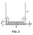
- Fig. 2 is a view schematically showing a card outlet of the card cassette of the present invention.
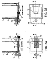
- Figs. 3A and 3B are views schematically indicating an operation for feeding out a card from the card cassette.
- Fig. 4 is on exploded perspective view of the card cassette.
- Fig 4 is used to describe a structure of the card cassette made according to the present invention.
- the card cassette comprises an outer box 1, an inner box 2, a shutter 3, a pair of slide guide members 4, a pair of slide springs 5, a pair of shutter springs 6, a spacer 7 (see Fig. 3A).
- the card cassette has a structure formed by inserting the inner box 2 carrying various parts into the outer box 1.
- the outer box 1 has a pair of pin holes 8 allowing a pair of pins 11 to insert therethrough.
- the pair of pins 11 are in practice for use in opening the shutter 3.
- the outer box 1 has a card outlet 14 and a kicker operating hole 15.
- the card cassette has a key-attached door (not shown) and a cassette handle (not shown), a window (not shown) for detecting an amount of remaining cards 20, a plate (not shown) for pressing a card 20 so as to prevent it from moving up or down when being transported, and a guide means (not shown) for making even the ends of several cards.
- a spacer 7 is provided on the key-attached door, so that the card 20 can be prevented from being accidentally taken out through the kicker operating hole 15.
- the inner box 2 also has a card outlet 14 which is so formed that it is possible to prevent two pieces of cards from lying one upon another when being fed out and is capable of feeding out a pre-embossed card.
- the inner box 2 has a kicker operating hole 15, sliding pins (not shown) capable of effecting a sliding movement of the slide guide members 4, a shutter pin (not shown) serving as a shaft capable of effecting an opening or closing movement of the shutter 3, and projections (not shown) for attaching and pulling the slide springs 5.
- each slide guide member 4 is located in a position of slide pin, and is connected with one slide spring 5 fixed on one projection.
- the shutter 3 is connected with the shutter pin and is interposed between the two shutter springs 6. In this way, a slide guide member 4, a slide spring 5 and a shutter spring 6 are provided on either side of the inner box 2.
- Figs. 1A and 1B there is indicated one of the pair of pins 11, which are provided for opening or closing the shutter 3.
- Each pin 11 is fixed on a table on which the card cassette is to be mounted so as to be set thereon.
- the kicker 12 is caused to move leftwardly and rightwardly in a manner as shown in the drawings (however, a driving section for operating the kicker 12 is not shown in the drawings).
- a driving section for operating the kicker 12 is not shown in the drawings.
- the kicker 12 when the kicker 12 is moved to the left (in the drawings), it will press the rear end of a card 20 so as to feed the card 20 out of the cassette. After the card 20 has been fed out, the kicker 12 is caused to move rightwardly so as to return to its home position.
- the pair of the feeding-out rollers 13 are disposed in front of a card outlet 14 of the cassette, with one roller positioned above the other. In this way, since the card 20 fed out by the kicker 12 is required to be moved away completely from the cassette, the pair of feeding-out rollers 13 are rotated in different directions shown by the arrows in the drawings, thereby feeding out the card 20 in a desired manner (however, a driving section for rotating the pair of feeding-out rollers 13 is not shown in the drawings).
- Fig. 1A is used to illustrate a condition before the card cassette is set onto the card producing apparatus.
- the shutter 3 is in its closed position.
- An operation for setting the card cassette onto the card producing apparatus may be completed by fitting a pair of pin holes 8 formed on the bottom of the cassette (the outer box 1) into a pair of pins 11, in a direction as shown by an arrow (1) in Fig. 1B.
- a notch 4a of each slide guide member 4 will be pressed by a pin 11.
- each slide guide member 4 will be caused to move to the right in a direction shown by an arrow (2) in Fig. 1B.
- FIG. 3A and 3B are used to illustrate a condition in which the card cassette has already been set on a card producing apparatus.
- a number of cards 20 are set within the inner box 2 (although only one card is shown in the drawings, there are in fact several such cards lying one upon another within the inner box).
- the shutter 3 is in its opened position.
- the kicker 12 is kept in its home position, and the pair of feeding-out rollers 13 are in their stopped state (see Fig. 3A).
- the kicker 12 is at first moved to the left end of the kicker operating hole 15 (see Fig. 3B), so that it stops its movement of outwardly pushing the card 20, and finally returns to its home position.
- the card 20 pushed out by the kicker 12 is at first positioned in front of the card outlet 14 of the card cassette, and then caught between the two feeding-out rollers 13 (in rotation) so as to be further fed out, thereby enabling the card 20 to be completely separated from the card cassette.
- the rotation of the pair of feeding-out rollers 13 will be stopped.
- Fig. 2 is used to indicate the inner box 2 or the card cassette, showing a state when viewed through the front side thereof, with the hatched portion representing the card outlet 14.
- the card outlet 14 has such a structure that it is narrow at its two ends but broad in its middle. With the use of such a structure, it is possible to smoothly feed out not only a virgin card which has not been embossed, but also an embossed card.
- a thickness h1 of each end portion of the card outlet 14 has a value which is larger than the thickness of one virgin card (according to JIS, 0.76 mm ⁇ 0.08 mm), but smaller than a total thickness of two pieces of such virgin cards.
- a width L1 is so set that it will not touch an embossed area of a card (according to JIS, an embossed area of a card should be set so as to have a size extending between 2.54 mm from the lower edge of the card and 24.03 mm from the same lower edge of the same card. Therefore, said width is only required to be smaller than 2.54 mm from which an embossed area begins to extend.
- the width h2 of the middle portion of the outlet is so set that it will not touch an embossed area of an embossed card (according to JIS, the height of embossed characters as 0.48 mm + 0/-0.08 mm from the surface of an embossed card. Therefore, when the thickness of a card is added, a total thickness viii be 1.32 mm at most, but is preferred to be 1.5 mm or more. Moreover, if we take into account a possible warpage of a card, it is preferred that the total thickness be 2.6 mm or more).
- the card outlet 14 having the above shape decided by the above mentioned size is so formed that each end of the card outlet 14 has a width h1 which allows the passing of only one card. For this reason, it is sure to exactly prevent the feeding-out of two cards lying one upon another, thereby avoiding the feeding-out of two cards at the same time.
- the middle portion of the card outlet it is possible to smoothly feed out an embossed card on which embossed characters have been formed in advance.
- a method of taking the card 20 out of the card cassette is a normal operation which may be carried out by using a key for the door of the cassette so as to open the door of the card cassette.
- the card cassette itself can be broken in order to take out the cards 20, or the cards 20 can be taken out through the card outlet 14.
- the cards 20 can be taken out through the kicker operating hole 15. Accordingly, the following description will be given only to explain how a security can be established for a method of taking out the card 20 through the card outlet 14 and a method of taking out the card 20 through the kicker operating hole 15.
- an explanation about a security for preventing this action is therefore omitted hereby.
- the shutter 3 is provided on the inner box 2. Since the shutter 3 can be opened only after it has been set in the card producing apparatus, when the card cassette is released from the card producing apparatus, the shutter can not be opened easily. For this reason, it is sure for the card cassette to obtain a security of preventing the cards 20 from being illegally taken out of the card cassette.
- the kicker 12 since the kicker 12 is used to push out the card 20, it is absolutely necessary for the kicker 12 to have a connecting portion capable of contacting from the outside of the card cassette to the cards 20 within the cassette, so that it is possible for the kicker 12 to contact from the kicker operating hole 15 to the cards 20 in the card cassette.
- a spacer 7 is installed (in a manner shown in Figs. 3A and 3B) on the inner side of the cassette door attached on the outer box 1, it is sure to prevent a card 20 from being taken out.
- the spacer 7 is made to be larger than the width of the kicker operating hole 15, the diagonal line L of a rectangular shape of the kicker operating hole 15 within the inner box 2 is set to be shorter than a shorter edge of a card 20 (see Fig. 3A which is a bottom view of the card cassette). Further, the spacer 7 is required to be attached as close as possible to the bottom of the outer box 1, in a manner such that even if the kicker 12 is operated, it will not touch the spacer 7. Accordingly, since the spacer 7 is attached in the above mentioned manner, it is sure to exactly prevent the cards 20 from being taken out of the card cassette even if the cards within the cassette is made vertical, horizontal or inclined.
- Fig. 5 is used to schematically indicate an example in which a pair of pins are located in the front of the apparatus.
- the card cassette (outer box 1) has a relative movement (in a direction (1) shown in the drawing) so that the pins 11 provided on the card outlet side of the apparatus are inserted into the card cassette, each pin 11 will be caused to push each slide guide member 4.
- each slide guide member 4 will be pressed by a pin 11 so as to be moved to the right (in a direction (2) shown in the drawing), thereby opening the shutter 3 (in a direction (3) shown in the drawing).
- the present invention has a structure in which a pair of pins are used to open the shutter, it is also possible to use several pairs of such pins to open the shutter. With the use of several pairs, of pins, it can be expected that the desired security can be further improved.
- Fig. 6 is used to schematically indicate an example which employs two pairs of pins.
- a necessary operation is only to effect a relative movement (in a direction (1) shown in the drawing) of the card cassette (the outer box 1) so that a pair of pins 11a provided on the card outlet side are inserted into the cassette.
- each pin 11a will be caused to push a slide guide member 4 (in a direction (2) shown in the drawing).
- the cassette is caused to have a relative movement (in a direction (3) shown in the drawing) so that a pair of pins 11b provided on the bottom surface of the apparatus are caused to insert into the cassette.
- each slide guide member 4 is moved still further to the right (in a direction (4) shown in the drawing). In this way, since each slide guide member 4 is exactly moved to the right, it is sure to exactly open the shutter 3 (in a direction (5) shown in the drawing).
- a pair of pins may be arranged in a manner such that the right pin is located in front of the card outlet and the left pin is located on the bottom surface of the apparatus, thereby forming a structure capable of opening the shutter.
Landscapes
- Physics & Mathematics (AREA)
- General Physics & Mathematics (AREA)
- Engineering & Computer Science (AREA)
- Theoretical Computer Science (AREA)
- Sheets, Magazines, And Separation Thereof (AREA)
- Conveying Record Carriers (AREA)
- Packaging Of Annular Or Rod-Shaped Articles, Wearing Apparel, Cassettes, Or The Like (AREA)
Applications Claiming Priority (2)
| Application Number | Priority Date | Filing Date | Title |
|---|---|---|---|
| JP10806899 | 1999-04-15 | ||
| JP10806899A JP3377038B2 (ja) | 1999-04-15 | 1999-04-15 | カード用カセット |
Publications (3)
| Publication Number | Publication Date |
|---|---|
| EP1045332A2 true EP1045332A2 (de) | 2000-10-18 |
| EP1045332A3 EP1045332A3 (de) | 2002-07-31 |
| EP1045332B1 EP1045332B1 (de) | 2010-01-20 |
Family
ID=14475079
Family Applications (1)
| Application Number | Title | Priority Date | Filing Date |
|---|---|---|---|
| EP00108286A Expired - Lifetime EP1045332B1 (de) | 1999-04-15 | 2000-04-14 | Kassette für Karten |
Country Status (4)
| Country | Link |
|---|---|
| US (1) | US6345727B1 (de) |
| EP (1) | EP1045332B1 (de) |
| JP (1) | JP3377038B2 (de) |
| DE (1) | DE60043717D1 (de) |
Cited By (1)
| Publication number | Priority date | Publication date | Assignee | Title |
|---|---|---|---|---|
| CN110533121A (zh) * | 2019-01-11 | 2019-12-03 | 艾斯特国际安全技术(深圳)有限公司 | 一种卡本通用送料机构 |
Families Citing this family (10)
| Publication number | Priority date | Publication date | Assignee | Title |
|---|---|---|---|---|
| EP1920413B1 (de) * | 2005-07-27 | 2019-05-22 | Crane Payment Innovations, Inc. | Kassette zum speichern von geldscheinen und dergleichen |
| JP4604003B2 (ja) * | 2006-01-24 | 2010-12-22 | 日本電産サンキョー株式会社 | カード発行機及びシャッタ機構 |
| JP2007217064A (ja) * | 2006-02-14 | 2007-08-30 | Glory Ltd | カード装填装置 |
| CN101878490B (zh) * | 2007-11-30 | 2013-08-28 | 日本信号株式会社 | 单程票ic卡的回收系统、用于它的通用票箱、售票机及检票机 |
| JP5119476B2 (ja) * | 2008-05-16 | 2013-01-16 | 旭精工株式会社 | カードの送り出し装置用カセット及びその解体装置 |
| KR101608892B1 (ko) | 2015-03-19 | 2016-04-04 | 아사히 세이코 가부시키가이샤 | 카드 카세트 장치 및 이 카드 카세트 장치를 이용하는 카드 불출 장치 |
| JP6818248B2 (ja) * | 2016-11-11 | 2021-01-20 | 大日本印刷株式会社 | カード供給システム |
| CN107292356B (zh) * | 2017-08-05 | 2023-06-06 | 广州明森科技股份有限公司 | 一种可防止卡片掉落的卡盒以及应用该卡盒的发卡装置 |
| JP2019064792A (ja) * | 2017-09-29 | 2019-04-25 | 大日本印刷株式会社 | カード供給装置 |
| JP7570701B2 (ja) * | 2022-01-14 | 2024-10-22 | 旭精工株式会社 | カード処理装置 |
Family Cites Families (7)
| Publication number | Priority date | Publication date | Assignee | Title |
|---|---|---|---|---|
| US3887106A (en) * | 1973-11-07 | 1975-06-03 | Ibm | Ticket cartridge and hopper and stacker therefor |
| US4186977A (en) * | 1978-10-18 | 1980-02-05 | International Business Machines Corporation | Self-locking depository container |
| GB2131082A (en) * | 1982-11-19 | 1984-06-13 | De La Rue Syst | Secure containers |
| GB2136498B (en) * | 1983-03-16 | 1986-07-09 | Burroughs Corp | Money cassette for an autoteller |
| JPS60244720A (ja) * | 1984-05-19 | 1985-12-04 | Omron Tateisi Electronics Co | 紙葉類収納装置 |
| JPH01173288A (ja) * | 1987-12-28 | 1989-07-07 | Maasu Eng:Kk | カード発券装置 |
| JPH10250856A (ja) * | 1997-03-12 | 1998-09-22 | Asahi Seiko Co Ltd | カード払い出し装置システム |
-
1999
- 1999-04-15 JP JP10806899A patent/JP3377038B2/ja not_active Expired - Fee Related
-
2000
- 2000-04-14 DE DE60043717T patent/DE60043717D1/de not_active Expired - Lifetime
- 2000-04-14 EP EP00108286A patent/EP1045332B1/de not_active Expired - Lifetime
- 2000-04-17 US US09/550,795 patent/US6345727B1/en not_active Expired - Fee Related
Cited By (1)
| Publication number | Priority date | Publication date | Assignee | Title |
|---|---|---|---|---|
| CN110533121A (zh) * | 2019-01-11 | 2019-12-03 | 艾斯特国际安全技术(深圳)有限公司 | 一种卡本通用送料机构 |
Also Published As
| Publication number | Publication date |
|---|---|
| JP2000302253A (ja) | 2000-10-31 |
| DE60043717D1 (de) | 2010-03-11 |
| US6345727B1 (en) | 2002-02-12 |
| EP1045332B1 (de) | 2010-01-20 |
| EP1045332A3 (de) | 2002-07-31 |
| JP3377038B2 (ja) | 2003-02-17 |
Similar Documents
| Publication | Publication Date | Title |
|---|---|---|
| EP0871150B1 (de) | Kartenausgagekassette | |
| US6345727B1 (en) | Card cassette | |
| US6843409B2 (en) | Media container module | |
| US10954061B2 (en) | Card cassette device and card dispensing apparatus using the same | |
| US4470356A (en) | Word processor-controlled printer output bin lock box | |
| US6176423B1 (en) | Shutter device having linkage which locks shutter as well as opens and closes the same | |
| JPH0561679B2 (de) | ||
| JP3341113B2 (ja) | インターロック機構 | |
| CN1689830B (zh) | 机壳和带锁定装置的打印机 | |
| JP2500110B2 (ja) | 鍵管理機における鍵管理施錠一斉解錠装置 | |
| US4318354A (en) | Automatic teller machine | |
| JPH07217282A (ja) | 自動販売機、両替機等における施錠金庫 | |
| JP2578522B2 (ja) | 紙幣収納カセット | |
| JP2513134Y2 (ja) | カ―ドカセットボックス | |
| JPH03206274A (ja) | 着脱式金庫のロック機構 | |
| JPS6127026Y2 (de) | ||
| KR200374671Y1 (ko) | 현금자동지급기용 부스의 도어 잠금장치 | |
| JPS6222387Y2 (de) | ||
| JP2003006704A (ja) | 硬貨回収金庫、および自動販売機 | |
| JP2569265Y2 (ja) | 係止確認機構 | |
| JP2503818Y2 (ja) | 紙幣出金機の金庫設定機構 | |
| JP2004044249A (ja) | リジェクトカード回収庫のシャッタロック機構 | |
| JP3019588B2 (ja) | 自動販売機の外扉ロック装置 | |
| JPS6327247Y2 (de) | ||
| JP2512151B2 (ja) | 紙幣放出口のシャッタ機構 |
Legal Events
| Date | Code | Title | Description |
|---|---|---|---|
| PUAI | Public reference made under article 153(3) epc to a published international application that has entered the european phase |
Free format text: ORIGINAL CODE: 0009012 |
|
| AK | Designated contracting states |
Kind code of ref document: A2 Designated state(s): AT BE CH CY DE DK ES FI FR GB GR IE IT LI LU MC NL PT SE |
|
| AX | Request for extension of the european patent |
Free format text: AL;LT;LV;MK;RO;SI |
|
| PUAL | Search report despatched |
Free format text: ORIGINAL CODE: 0009013 |
|
| AK | Designated contracting states |
Kind code of ref document: A3 Designated state(s): AT BE CH CY DE DK ES FI FR GB GR IE IT LI LU MC NL PT SE |
|
| AX | Request for extension of the european patent |
Free format text: AL;LT;LV;MK;RO;SI |
|
| 17P | Request for examination filed |
Effective date: 20021111 |
|
| AKX | Designation fees paid |
Designated state(s): DE GB IT |
|
| 17Q | First examination report despatched |
Effective date: 20071009 |
|
| GRAP | Despatch of communication of intention to grant a patent |
Free format text: ORIGINAL CODE: EPIDOSNIGR1 |
|
| GRAS | Grant fee paid |
Free format text: ORIGINAL CODE: EPIDOSNIGR3 |
|
| GRAA | (expected) grant |
Free format text: ORIGINAL CODE: 0009210 |
|
| AK | Designated contracting states |
Kind code of ref document: B1 Designated state(s): DE GB IT |
|
| REG | Reference to a national code |
Ref country code: GB Ref legal event code: FG4D |
|
| REF | Corresponds to: |
Ref document number: 60043717 Country of ref document: DE Date of ref document: 20100311 Kind code of ref document: P |
|
| PGFP | Annual fee paid to national office [announced via postgrant information from national office to epo] |
Ref country code: GB Payment date: 20100317 Year of fee payment: 11 |
|
| PGFP | Annual fee paid to national office [announced via postgrant information from national office to epo] |
Ref country code: IT Payment date: 20100427 Year of fee payment: 11 |
|
| PLBE | No opposition filed within time limit |
Free format text: ORIGINAL CODE: 0009261 |
|
| STAA | Information on the status of an ep patent application or granted ep patent |
Free format text: STATUS: NO OPPOSITION FILED WITHIN TIME LIMIT |
|
| PGFP | Annual fee paid to national office [announced via postgrant information from national office to epo] |
Ref country code: DE Payment date: 20100629 Year of fee payment: 11 |
|
| 26N | No opposition filed |
Effective date: 20101021 |
|
| REG | Reference to a national code |
Ref country code: DE Ref legal event code: R119 Ref document number: 60043717 Country of ref document: DE |
|
| REG | Reference to a national code |
Ref country code: DE Ref legal event code: R119 Ref document number: 60043717 Country of ref document: DE |
|
| GBPC | Gb: european patent ceased through non-payment of renewal fee |
Effective date: 20110414 |
|
| PG25 | Lapsed in a contracting state [announced via postgrant information from national office to epo] |
Ref country code: GB Free format text: LAPSE BECAUSE OF NON-PAYMENT OF DUE FEES Effective date: 20110414 Ref country code: IT Free format text: LAPSE BECAUSE OF NON-PAYMENT OF DUE FEES Effective date: 20110414 |
|
| PG25 | Lapsed in a contracting state [announced via postgrant information from national office to epo] |
Ref country code: DE Free format text: LAPSE BECAUSE OF NON-PAYMENT OF DUE FEES Effective date: 20111031 |