EP1045491A1 - Verbindungsverfahren und -anordnung für Anschlussklemmen - Google Patents
Verbindungsverfahren und -anordnung für Anschlussklemmen Download PDFInfo
- Publication number
- EP1045491A1 EP1045491A1 EP00420066A EP00420066A EP1045491A1 EP 1045491 A1 EP1045491 A1 EP 1045491A1 EP 00420066 A EP00420066 A EP 00420066A EP 00420066 A EP00420066 A EP 00420066A EP 1045491 A1 EP1045491 A1 EP 1045491A1
- Authority
- EP
- European Patent Office
- Prior art keywords
- connection
- stripping
- slot
- interconnection
- plugs
- Prior art date
- Legal status (The legal status is an assumption and is not a legal conclusion. Google has not performed a legal analysis and makes no representation as to the accuracy of the status listed.)
- Granted
Links
- 238000000034 method Methods 0.000 title claims description 8
- 229920002994 synthetic fiber Polymers 0.000 claims description 2
- 238000003780 insertion Methods 0.000 description 3
- 230000037431 insertion Effects 0.000 description 3
- 230000014759 maintenance of location Effects 0.000 description 2
- 239000002184 metal Substances 0.000 description 2
- 229910052751 metal Inorganic materials 0.000 description 2
- 229910000881 Cu alloy Inorganic materials 0.000 description 1
- 241001080024 Telles Species 0.000 description 1
- 240000008042 Zea mays Species 0.000 description 1
- 230000006978 adaptation Effects 0.000 description 1
- 210000004027 cell Anatomy 0.000 description 1
- 238000006073 displacement reaction Methods 0.000 description 1
- 230000000694 effects Effects 0.000 description 1
- 238000009413 insulation Methods 0.000 description 1
- 238000004519 manufacturing process Methods 0.000 description 1
- 210000000056 organ Anatomy 0.000 description 1
- 230000000717 retained effect Effects 0.000 description 1
Images

Classifications
-
- H—ELECTRICITY
- H01—ELECTRIC ELEMENTS
- H01R—ELECTRICALLY-CONDUCTIVE CONNECTIONS; STRUCTURAL ASSOCIATIONS OF A PLURALITY OF MUTUALLY-INSULATED ELECTRICAL CONNECTING ELEMENTS; COUPLING DEVICES; CURRENT COLLECTORS
- H01R31/00—Coupling parts supported only by co-operation with counterpart
- H01R31/08—Short-circuiting members for bridging contacts in a counterpart
Definitions
- the present invention relates to a method and a device interconnection of connection terminals, in particular of connection terminals self-stripping connection.
- interconnect organs electrical such as terminal blocks
- These electrical components generally include a reception structure which is possibly constituted by a female part designed specifically to receive a type of clamp.
- This structure can be reduce to an opening made in a connection element, by example of a conductive strip type, to allow insertion and establishing electrical contact between this connection element and pliers.
- interconnection strips To make a connection between several electrical components, for example, terminal blocks, neighbors, it is known to use interconnection strips. Bars of this type are made with the number of clamps desired by the user. Documents DE-44 11 306 or FR 2 764 445 disclose such interconnection bars. Use of these strips assumes that the electrical components to be interconnected have a structure intended to receive a clamp.
- terminal blocks that are designed without structure allowing interconnection with neighboring terminal blocks.
- Such terminal blocks are for example blocks which have been designed with a concern for miniaturization.
- the object of the present invention is to provide a new process and a new interconnection device for such terminals of connection.
- This device can advantageously be used with terminal blocks fitted with connection terminals as described and claimed in document EP-0 247 360.
- a terminal connection comprises a conductive connection piece, with slot stripping and holding straight for the souls of the wires, which is immobilized in a housing of an insulating housing itself provided with a opening which extends opposite the stripping and retaining slot for allow the insertion of the wires transversely above the mouthpiece stripping that includes this slot and the immobilization of the sheaths insulating wires whose core is retained in said slot.
- the slot is longitudinally formed along a part in the form of a profile of the conductive part which has, at this level, a cross-section hollow polygonal transverse allowing guiding in translation along the slot of an external tool attachment intended to slide both from on either side and between the folds delimiting the edges of the slot, so pushing the wires into this slot in a transverse position with respect to it, by being guided in the internal cavity of the profiled part, said end piece of tool being guided in translation from the outside of the insulating housing towards said cavity by the edges of a hole made in said insulating housing at this effect.
- the method according to the invention is a method of interconnecting connection terminals with a stripping and retaining slot, at using an interconnection comb comprising a connecting bar to from which extend contact cards.
- the free end of the contact plugs forms a clamp and the interconnection between two connection terminals is made by pinching using the end of two contact plugs the edges of the stripping slots and corresponding retainers.
- the pinching is carried out at the end of the zone of the stripping and retaining slot intended to ensure the retention of a wire to be connected, end located on the side of which the introduction is made in the slot of the wire to be connected.
- this is an area where a good contact is possible and easily accessible since it is planned to access it with the wire to be connected.
- the invention also provides a device for interconnecting connection terminals with a connecting strip from which extend from contact cards.
- the connecting bar extends in a plane perpendicular to the direction of extension of the cards; at the level of each connection terminal, extends from the two longitudinal edges opposite of the connection strip each time a connection plug, and two connection plugs facing each other form a clamp.
- Such a device is easy to make. Indeed, it suffices to cut and fold a metal strip to make such a device. he these are simple and common operations. The cost price of such room is low.
- the pliers can take place the edges of the slot of the conductive part.
- the cards then work by deviating each other while in the usual interconnection devices, two cards facing each other work closer together one from the other.
- a tooth extends each time between two cards, in the plane of the connecting bar, on each edge longitudinal of the bar.
- the interconnection device according to this invention can then also include an insulating protection formed by an extruded insulating plastic profile threaded onto the teeth of the two opposite longitudinal edges of the connecting bar.
- An interconnection device is for example intended to come interconnect terminals for stripping and stripping retainers each placed in an insulating housing having an opening to allow passage and guiding in translation of an external tool provided for driving a wire between pleats delimiting the edges of the slot stripping and restraint.
- a connection terminal is described by example in patent EP-0 247 360.
- the plugs are advantageously spaced from each other and have a width such that they are guided by the opening provided for the passage and guidance of the external tool and the side of their free end the plugs, in the connection position, are placed preferably on both sides of the folds delimiting the edges of the slot of stripping and restraint.
- connection terminal In this configuration, it is useless to plan at the level of the connection terminal an adaptation to allow connection with a neighboring connection terminal since the connection is made by a hole originally intended for the passage of an external tool allowing the connection of a wire to be connected in the terminal connection.
- connection device In the case where the connection device according to the invention is intended to interconnect slotted connection terminals stripping and retaining each placed in an insulating housing having an opening to allow passage and guiding in translation of a external tool intended to drive a wire between folds delimiting the edges of the stripping and retaining slot, the insulating housing having a rim intended to receive a hooking projection of the external tool, then each sheet advantageously has a boss intended to come and take place in the hooking rim in connection position of the clamp. This allows the connection device to be kept in the connected position.
- a connection terminal is described for example in the patent EP-0 265 321.
- pre-cuts are advantageously provided on the link bar.
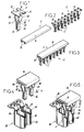
- the interconnection device according to the invention shown in the Figure 2 consists of two separate parts: a comb interconnection 2 and an insulating cap 4.
- the interconnection comb 2 is a succession of pliers 6 as shown in Figure 1.
- This comb 2 is made from a metal strip, for example of tinned copper alloy, cut and folded.
- the interconnection comb 2 has a connecting bar 8, plugs 10 which two by two form a clamp 6, as well as teeth 12.
- the connecting bar 8 extends in a plane hereinafter called horizontal plane. Sheets 10 all extend on the same side of this plane horizontal in a general direction perpendicular to this plane and called vertical direction. We will consider that the sheets 10 extend vertically down. Sheets 10 each extend from a longitudinal edge 14 of the connecting bar 8. At each plug 10 corresponds a second plug 10 which forms with this first a clamp 6. The two cards 10 face each other and the second card 10 leaves the edge longitudinal opposite to the longitudinal edge from which the first extends file 10.
- a tooth 12 Between two sheets 10 extending from the same edge longitudinal 14 of the connecting bar 8, is each time a tooth 12. The latter also starts from the longitudinal edge 14 but extends in the horizontal plane. The shape of the connecting bar 8 with the teeth 12 thus recalls the shape of a succession of H placed next to the other.
- the insulating cap 4 is made of insulating synthetic material electrically. It is an extruded profile having a flat face 16 intended to cover the connecting bar 8 and the teeth 12. The edges longitudinal of the flat face 16 have returns 18 intended for come and grasp the free end of the teeth 12 from below. This profile can thus slide on the interconnection comb at the level of the connection 8 and teeth 12.
- each sheet 10 extends perpendicular to the connecting strip 8 from a longitudinal edge 14 thereof. From the longitudinal edge 14, each sheet 10 has a guide face 20, a narrowing 22, a jaw region 24 as well as a curved end 26 ( Figure 6).
- the guide face 20 is a flat face extending perpendicular to the connecting bar 8 and to the horizontal plane.
- a boss 28 is provided in the plane of the guide face 20 on an edge of this one.
- the constriction 22 is in an inclined plane relative to to the guide face 20. It extends towards the second plug 10 forming with the sheet described here a clamp 6. This narrowing zone 22 has a less width compared to the guide face 20.
- the jaw region 24 forms an angle of a few degrees with the perpendicular to the horizontal plane so that the two jaw-forming zones 24 facing each other approach one of the other by moving away from the connection bar 8.
- end 26 of the jaw region 24 is curved outward, that is, away from the other plug of the pliers.
- the two jaw areas 24 are intended to come sandwich a conductive part to be interconnected.
- Figure 4 shows an interconnection device such as that described above as well as two connection pieces 30 to be connected electrically.
- connection pieces 30 include the characteristics, with regard to their shape, of connecting pieces already known by patents of the prior art such as for example the document EP-0 247 360 or EP-0 265 321.
- Each piece 30 has a stripping and stripping slot 32 retainer which is straight and parallel to the longitudinal axis of the workpiece 30 profiled connection. It is for example obtained from a flat side by stamping resulting in cutting, then folding and possibly localized thinning.
- the connecting piece 30 here has a cross section hollow polygon which corresponds to a U with a base 34 and two branches 36 whose free ends have been obliquely and also folded towards each other.
- the free end of each folded part 38 forms an edge of the stripping and retaining slot 32. These parts 38 are eventually gradually thinned towards the slot 32.
- the stripping and retaining slot 32 presents at one of its ends a stripped mouth 40.
- the latter is obtained by symmetrical oblique cutout of the folded parts 38 at their ends. This oblique cut makes it possible to obtain a flared mouthpiece, the edges form an edge allowing to start a sheath of a pushed wire in the mouth.
- the contact between a plug 10 and a connection piece 30 is made at level of the edges of the slot 32, on the side of the mouth 40, in a zone of the slot 32 intended to carry out the retention of an electric wire to connect.
- a jaw region 24 of the plug 10 is then located at the interior of the hollow polygonal section profile while the area forming jaw 24 of the card 10 which is associated therewith is the outside of this profile.
- the presence of the curved ends 26 on the plugs 10 facilitates the spacing of the plugs 10 which is caused when the contact between the plug 10 and the connection piece 30 is established.
- Figures 6 and 7 show the connection pieces 30 of the Figures 4 and 5 in place in an insulating housing 42 of a terminal block. This last corresponds to a terminal block as described in the patent European No. 0 265 321.
- This housing 42 has an insertion opening 44 intended for the passage of a blade of an external tool making it possible to make the connection of a wire at the connection piece 30.
- This introduction port 44 is provided with hooking edges 46 intended for receive movable fastening elements carried by the tool end as described in patent EP-0 265 321.
- the pliers 6 of the interconnection comb 2 passes through the introduction orifice 44 for making the electrical connection between two 30 connecting parts nearby.
- the boss 28 of each guide face 20 is placed so that when the connection between the plug 10 and the corresponding connecting piece 30 is made, the boss 28 comes take place just below the hanging edge 46. This allows then maintaining the interconnection comb 2 in place on the block junction.
- the interconnection device described above is particularly simple to make. Indeed, the cutting and folding are automated and commonly used operations.
- the fact to have an insulating cap 4 threading on the interconnection comb also facilitates the production of the interconnection device.
- Another advantage of the interconnection device described above is that it can come and take place on terminal blocks which have no particular structure intended to receive a comb interconnection. Indeed, the device described comes to connect at the level an orifice whose primary function is the passage of a tool allowing to connect a wire to the connection piece located at inside the terminal block.
Landscapes
- Connector Housings Or Holding Contact Members (AREA)
- Connections Arranged To Contact A Plurality Of Conductors (AREA)
- Coupling Device And Connection With Printed Circuit (AREA)
Applications Claiming Priority (2)
| Application Number | Priority Date | Filing Date | Title |
|---|---|---|---|
| FR9904683A FR2792118B1 (fr) | 1999-04-12 | 1999-04-12 | Procede et dispositif d'interconnexion de bornes de raccordement |
| FR9904683 | 1999-04-12 |
Publications (2)
| Publication Number | Publication Date |
|---|---|
| EP1045491A1 true EP1045491A1 (de) | 2000-10-18 |
| EP1045491B1 EP1045491B1 (de) | 2008-01-23 |
Family
ID=9544398
Family Applications (1)
| Application Number | Title | Priority Date | Filing Date |
|---|---|---|---|
| EP00420066A Expired - Lifetime EP1045491B1 (de) | 1999-04-12 | 2000-04-05 | Verbindungsverfahren und -anordnung für Anschlussklemmen |
Country Status (5)
| Country | Link |
|---|---|
| US (1) | US6402548B1 (de) |
| EP (1) | EP1045491B1 (de) |
| DE (1) | DE60037848T2 (de) |
| ES (1) | ES2298124T3 (de) |
| FR (1) | FR2792118B1 (de) |
Families Citing this family (10)
| Publication number | Priority date | Publication date | Assignee | Title |
|---|---|---|---|---|
| ES2199030B1 (es) * | 2001-09-07 | 2005-05-01 | Ge Power Controls Iberica, S.L. | Sistema de conexion electrica entre modulos para la proteccion de circuitos de distribucion electrica. |
| DE10156214B4 (de) * | 2001-11-15 | 2006-04-20 | Siemens Ag | Mehrphasiges Sammelschienensystem |
| US7153157B2 (en) * | 2005-01-19 | 2006-12-26 | Ekstrom Industries, Inc. | Terminal block jumper |
| US7232335B2 (en) * | 2005-05-13 | 2007-06-19 | Ekstrom Industries, Inc. | K-series watthour meter socket adapter |
| US7540792B2 (en) * | 2006-08-07 | 2009-06-02 | General Electric Company | Switching apparatus |
| FR2913541B1 (fr) * | 2007-03-09 | 2009-07-03 | Abb France | Dispositif conducteur pour le contact electrique d'une gaine de blindage d'un conducteur |
| JP5612831B2 (ja) * | 2009-05-20 | 2014-10-22 | モレックス インコーポレイテドMolex Incorporated | ループコネクタ及び閉回路形成コネクタ |
| CN102834987B (zh) * | 2010-03-25 | 2015-04-15 | 矢崎总业株式会社 | 接头连接器和用于识别接头连接器中的汇流条图案的方法 |
| US8979577B2 (en) * | 2013-06-24 | 2015-03-17 | Dinkle Enterprise Co., Ltd. | Bridging terminal |
| US12191593B2 (en) * | 2022-08-29 | 2025-01-07 | Dinkle Enterprise Co., Ltd. | Jumper terminal belt structure |
Citations (5)
| Publication number | Priority date | Publication date | Assignee | Title |
|---|---|---|---|---|
| US4456317A (en) * | 1983-03-10 | 1984-06-26 | Amp Incorporated | Commoning strip |
| EP0188034A1 (de) * | 1984-12-28 | 1986-07-23 | E.I. Du Pont De Nemours And Company | Elektrischer Verbinder mit Kontakthaltemechanismus |
| EP0247360A1 (de) * | 1986-04-28 | 1987-12-02 | Entrelec Sa | Verbindungsanordnung mit einem Schlitz für einen elektrischen Leiter und Spitze für ein entsprechendes Verbindungswerkzeug |
| US5201667A (en) * | 1990-06-27 | 1993-04-13 | Yazaki Corporation | Branch circuit structure |
| EP0601538A2 (de) * | 1992-12-09 | 1994-06-15 | Sumitomo Wiring Systems, Ltd. | Verbinder |
Family Cites Families (6)
| Publication number | Priority date | Publication date | Assignee | Title |
|---|---|---|---|---|
| US3503036A (en) * | 1968-03-27 | 1970-03-24 | Amp Inc | Contact terminals and manufacturing method |
| US4944692A (en) * | 1989-02-24 | 1990-07-31 | Allina Edward F | Electrical plug-in connectors |
| US5462459A (en) * | 1994-09-30 | 1995-10-31 | Cardell Corporation | Spring-type electrical receptacle |
| US5609493A (en) * | 1995-03-16 | 1997-03-11 | Hon Hai Precision Ind. Co., Ltd. | Device for short-circuiting for use with connector |
| US5816851A (en) * | 1995-03-16 | 1998-10-06 | Hon Hai Precision Ind. Co., Ltd. | Device for short-circuiting for use with connector |
| DE29504996U1 (de) * | 1995-03-24 | 1995-07-13 | Stocko Metallwarenfab Henkels | Elektrisches Kontaktelement |
-
1999
- 1999-04-12 FR FR9904683A patent/FR2792118B1/fr not_active Expired - Fee Related
-
2000
- 2000-04-05 DE DE60037848T patent/DE60037848T2/de not_active Expired - Lifetime
- 2000-04-05 ES ES00420066T patent/ES2298124T3/es not_active Expired - Lifetime
- 2000-04-05 EP EP00420066A patent/EP1045491B1/de not_active Expired - Lifetime
- 2000-04-06 US US09/544,331 patent/US6402548B1/en not_active Expired - Fee Related
Patent Citations (5)
| Publication number | Priority date | Publication date | Assignee | Title |
|---|---|---|---|---|
| US4456317A (en) * | 1983-03-10 | 1984-06-26 | Amp Incorporated | Commoning strip |
| EP0188034A1 (de) * | 1984-12-28 | 1986-07-23 | E.I. Du Pont De Nemours And Company | Elektrischer Verbinder mit Kontakthaltemechanismus |
| EP0247360A1 (de) * | 1986-04-28 | 1987-12-02 | Entrelec Sa | Verbindungsanordnung mit einem Schlitz für einen elektrischen Leiter und Spitze für ein entsprechendes Verbindungswerkzeug |
| US5201667A (en) * | 1990-06-27 | 1993-04-13 | Yazaki Corporation | Branch circuit structure |
| EP0601538A2 (de) * | 1992-12-09 | 1994-06-15 | Sumitomo Wiring Systems, Ltd. | Verbinder |
Also Published As
| Publication number | Publication date |
|---|---|
| EP1045491B1 (de) | 2008-01-23 |
| DE60037848D1 (de) | 2008-03-13 |
| US6402548B1 (en) | 2002-06-11 |
| FR2792118B1 (fr) | 2001-06-01 |
| FR2792118A1 (fr) | 2000-10-13 |
| ES2298124T3 (es) | 2008-05-16 |
| DE60037848T2 (de) | 2009-01-22 |
Similar Documents
| Publication | Publication Date | Title |
|---|---|---|
| FR2810458A1 (fr) | Peigne d'interconnexion electrique | |
| EP0951094B1 (de) | Anschlusskontaktvorrichtung mit Schneidklemmverbinder | |
| EP0208233B1 (de) | Eingebaute Vorrichtung für elektrische Apparate zur abisolierfreien Verbindung und Verbindungswerkzeug für eine solche Vorrichtung | |
| FR2694456A1 (fr) | Prise femelle de type "modular jack" et à connectique intégrée. | |
| EP1045491B1 (de) | Verbindungsverfahren und -anordnung für Anschlussklemmen | |
| FR2494504A1 (fr) | Connecteur a sertir pour fils electriques | |
| FR2804797A1 (fr) | Dispositif de connexion auto-denudant pour deux cables electriques | |
| FR2584875A1 (fr) | Outil pour insertion de conducteur | |
| CH674598A5 (de) | ||
| EP0852824B1 (de) | Verbindungsvorrichtung für mindestens zwei ummantelden leitenden drähte | |
| FR2604565A1 (fr) | Connecteur electrique et borne pour ce connecteur | |
| EP2079133B1 (de) | Verbindungsklemme mit einem Steckelement zur Aufnahme eines elektrischen Steckerstifts, Steckdose, die eine solche Klemme umfasst, und Herstellungsverfahren einer solchen Klemme | |
| FR2585194A1 (fr) | Connecteur polyvalent pour la connexion de differents types de cables ou conducteurs electriques | |
| EP0062579B1 (de) | Verbindungsgerät | |
| WO1986003063A1 (fr) | Dispositif de connexion | |
| EP0881709B1 (de) | Geschlitzte Anschlussklemme für eine Verbindungsanordnung für mindestens eine elektrische Leiter | |
| FR2803442A1 (fr) | Piece de connexion auto-denudante pouvant etre reliee a une piece de connexion voisine | |
| EP0673089B1 (de) | Kabelkanal und dessen Herstellungsverfahren | |
| EP0083887A1 (de) | Verbinder | |
| FR2467490A1 (fr) | Organe de connexion electrique et boitier destine a contenir un tel organe | |
| FR2815775A1 (fr) | Prise de courants faibles du type "modular jack" comprenant un peigne amovible de positionnement des fils electriques au-dessus des contacts metalliques autodenudants | |
| EP0383135A1 (de) | Verbindervorrichtung für elektrisch isolierte Leiter in verschiedenen Höhen | |
| EP0509859B1 (de) | Elektrische Kontaktbuchse | |
| FR2659514A1 (fr) | Cordon en y pour l'adjonction d'un ecouteur supplementaire a un poste telephonique non prevu pour en comporter un. | |
| EP0470882A1 (de) | Elektrischer Schneidklemmenkontakt |
Legal Events
| Date | Code | Title | Description |
|---|---|---|---|
| PUAI | Public reference made under article 153(3) epc to a published international application that has entered the european phase |
Free format text: ORIGINAL CODE: 0009012 |
|
| AK | Designated contracting states |
Kind code of ref document: A1 Designated state(s): DE ES FR GB IT |
|
| AX | Request for extension of the european patent |
Free format text: AL;LT;LV;MK;RO;SI |
|
| 17P | Request for examination filed |
Effective date: 20010226 |
|
| AKX | Designation fees paid |
Free format text: DE ES FR GB IT |
|
| RAP1 | Party data changed (applicant data changed or rights of an application transferred) |
Owner name: ABB ENTRELEC |
|
| 17Q | First examination report despatched |
Effective date: 20070427 |
|
| GRAP | Despatch of communication of intention to grant a patent |
Free format text: ORIGINAL CODE: EPIDOSNIGR1 |
|
| RAP1 | Party data changed (applicant data changed or rights of an application transferred) |
Owner name: ABB FRANCE |
|
| GRAS | Grant fee paid |
Free format text: ORIGINAL CODE: EPIDOSNIGR3 |
|
| GRAA | (expected) grant |
Free format text: ORIGINAL CODE: 0009210 |
|
| AK | Designated contracting states |
Kind code of ref document: B1 Designated state(s): DE ES FR GB IT |
|
| REG | Reference to a national code |
Ref country code: GB Ref legal event code: FG4D Free format text: NOT ENGLISH |
|
| REF | Corresponds to: |
Ref document number: 60037848 Country of ref document: DE Date of ref document: 20080313 Kind code of ref document: P |
|
| GBT | Gb: translation of ep patent filed (gb section 77(6)(a)/1977) |
Effective date: 20080312 |
|
| REG | Reference to a national code |
Ref country code: ES Ref legal event code: FG2A Ref document number: 2298124 Country of ref document: ES Kind code of ref document: T3 |
|
| PLBE | No opposition filed within time limit |
Free format text: ORIGINAL CODE: 0009261 |
|
| STAA | Information on the status of an ep patent application or granted ep patent |
Free format text: STATUS: NO OPPOSITION FILED WITHIN TIME LIMIT |
|
| 26N | No opposition filed |
Effective date: 20081024 |
|
| PGFP | Annual fee paid to national office [announced via postgrant information from national office to epo] |
Ref country code: ES Payment date: 20090428 Year of fee payment: 10 |
|
| PGFP | Annual fee paid to national office [announced via postgrant information from national office to epo] |
Ref country code: GB Payment date: 20090421 Year of fee payment: 10 |
|
| GBPC | Gb: european patent ceased through non-payment of renewal fee |
Effective date: 20100405 |
|
| PG25 | Lapsed in a contracting state [announced via postgrant information from national office to epo] |
Ref country code: GB Free format text: LAPSE BECAUSE OF NON-PAYMENT OF DUE FEES Effective date: 20100405 |
|
| REG | Reference to a national code |
Ref country code: ES Ref legal event code: FD2A Effective date: 20110715 |
|
| PG25 | Lapsed in a contracting state [announced via postgrant information from national office to epo] |
Ref country code: ES Free format text: LAPSE BECAUSE OF NON-PAYMENT OF DUE FEES Effective date: 20110705 |
|
| PG25 | Lapsed in a contracting state [announced via postgrant information from national office to epo] |
Ref country code: ES Free format text: LAPSE BECAUSE OF NON-PAYMENT OF DUE FEES Effective date: 20100406 |
|
| PGFP | Annual fee paid to national office [announced via postgrant information from national office to epo] |
Ref country code: IT Payment date: 20110421 Year of fee payment: 12 |
|
| REG | Reference to a national code |
Ref country code: FR Ref legal event code: CA Effective date: 20120425 |
|
| REG | Reference to a national code |
Ref country code: FR Ref legal event code: RM Effective date: 20120827 |
|
| PG25 | Lapsed in a contracting state [announced via postgrant information from national office to epo] |
Ref country code: IT Free format text: LAPSE BECAUSE OF NON-PAYMENT OF DUE FEES Effective date: 20120405 |
|
| PGFP | Annual fee paid to national office [announced via postgrant information from national office to epo] |
Ref country code: DE Payment date: 20130419 Year of fee payment: 14 |
|
| PGFP | Annual fee paid to national office [announced via postgrant information from national office to epo] |
Ref country code: FR Payment date: 20130515 Year of fee payment: 14 |
|
| REG | Reference to a national code |
Ref country code: DE Ref legal event code: R119 Ref document number: 60037848 Country of ref document: DE |
|
| REG | Reference to a national code |
Ref country code: DE Ref legal event code: R119 Ref document number: 60037848 Country of ref document: DE Effective date: 20141101 |
|
| REG | Reference to a national code |
Ref country code: FR Ref legal event code: ST Effective date: 20141231 |
|
| PG25 | Lapsed in a contracting state [announced via postgrant information from national office to epo] |
Ref country code: DE Free format text: LAPSE BECAUSE OF NON-PAYMENT OF DUE FEES Effective date: 20141101 |
|
| PG25 | Lapsed in a contracting state [announced via postgrant information from national office to epo] |
Ref country code: FR Free format text: LAPSE BECAUSE OF NON-PAYMENT OF DUE FEES Effective date: 20140430 |