EP1045746B1 - Coupe automatique de pieces dans une matiere en feuille - Google Patents
Coupe automatique de pieces dans une matiere en feuille Download PDFInfo
- Publication number
- EP1045746B1 EP1045746B1 EP99942987A EP99942987A EP1045746B1 EP 1045746 B1 EP1045746 B1 EP 1045746B1 EP 99942987 A EP99942987 A EP 99942987A EP 99942987 A EP99942987 A EP 99942987A EP 1045746 B1 EP1045746 B1 EP 1045746B1
- Authority
- EP
- European Patent Office
- Prior art keywords
- cutting
- film
- sheet material
- sealing film
- installation
- Prior art date
- Legal status (The legal status is an assumption and is not a legal conclusion. Google has not performed a legal analysis and makes no representation as to the accuracy of the status listed.)
- Expired - Lifetime
Links
Images





Classifications
-
- B—PERFORMING OPERATIONS; TRANSPORTING
- B26—HAND CUTTING TOOLS; CUTTING; SEVERING
- B26D—CUTTING; DETAILS COMMON TO MACHINES FOR PERFORATING, PUNCHING, CUTTING-OUT, STAMPING-OUT OR SEVERING
- B26D7/00—Details of apparatus for cutting, cutting-out, stamping-out, punching, perforating, or severing by means other than cutting
- B26D7/01—Means for holding or positioning work
- B26D7/018—Holding the work by suction
-
- B—PERFORMING OPERATIONS; TRANSPORTING
- B26—HAND CUTTING TOOLS; CUTTING; SEVERING
- B26F—PERFORATING; PUNCHING; CUTTING-OUT; STAMPING-OUT; SEVERING BY MEANS OTHER THAN CUTTING
- B26F1/00—Perforating; Punching; Cutting-out; Stamping-out; Apparatus therefor
- B26F1/38—Cutting-out; Stamping-out
- B26F1/3806—Cutting-out; Stamping-out wherein relative movements of tool head and work during cutting have a component tangential to the work surface
- B26F1/3813—Cutting-out; Stamping-out wherein relative movements of tool head and work during cutting have a component tangential to the work surface wherein the tool head is moved in a plane parallel to the work in a coordinate system fixed with respect to the work
-
- Y—GENERAL TAGGING OF NEW TECHNOLOGICAL DEVELOPMENTS; GENERAL TAGGING OF CROSS-SECTIONAL TECHNOLOGIES SPANNING OVER SEVERAL SECTIONS OF THE IPC; TECHNICAL SUBJECTS COVERED BY FORMER USPC CROSS-REFERENCE ART COLLECTIONS [XRACs] AND DIGESTS
- Y10—TECHNICAL SUBJECTS COVERED BY FORMER USPC
- Y10T—TECHNICAL SUBJECTS COVERED BY FORMER US CLASSIFICATION
- Y10T156/00—Adhesive bonding and miscellaneous chemical manufacture
- Y10T156/10—Methods of surface bonding and/or assembly therefor
- Y10T156/1052—Methods of surface bonding and/or assembly therefor with cutting, punching, tearing or severing
- Y10T156/1054—Methods of surface bonding and/or assembly therefor with cutting, punching, tearing or severing and simultaneously bonding [e.g., cut-seaming]
-
- Y—GENERAL TAGGING OF NEW TECHNOLOGICAL DEVELOPMENTS; GENERAL TAGGING OF CROSS-SECTIONAL TECHNOLOGIES SPANNING OVER SEVERAL SECTIONS OF THE IPC; TECHNICAL SUBJECTS COVERED BY FORMER USPC CROSS-REFERENCE ART COLLECTIONS [XRACs] AND DIGESTS
- Y10—TECHNICAL SUBJECTS COVERED BY FORMER USPC
- Y10T—TECHNICAL SUBJECTS COVERED BY FORMER US CLASSIFICATION
- Y10T156/00—Adhesive bonding and miscellaneous chemical manufacture
- Y10T156/10—Methods of surface bonding and/or assembly therefor
- Y10T156/1052—Methods of surface bonding and/or assembly therefor with cutting, punching, tearing or severing
- Y10T156/1084—Methods of surface bonding and/or assembly therefor with cutting, punching, tearing or severing of continuous or running length bonded web
-
- Y—GENERAL TAGGING OF NEW TECHNOLOGICAL DEVELOPMENTS; GENERAL TAGGING OF CROSS-SECTIONAL TECHNOLOGIES SPANNING OVER SEVERAL SECTIONS OF THE IPC; TECHNICAL SUBJECTS COVERED BY FORMER USPC CROSS-REFERENCE ART COLLECTIONS [XRACs] AND DIGESTS
- Y10—TECHNICAL SUBJECTS COVERED BY FORMER USPC
- Y10T—TECHNICAL SUBJECTS COVERED BY FORMER US CLASSIFICATION
- Y10T156/00—Adhesive bonding and miscellaneous chemical manufacture
- Y10T156/12—Surface bonding means and/or assembly means with cutting, punching, piercing, severing or tearing
- Y10T156/1317—Means feeding plural workpieces to be joined
- Y10T156/1343—Cutting indefinite length web after assembly with discrete article
-
- Y—GENERAL TAGGING OF NEW TECHNOLOGICAL DEVELOPMENTS; GENERAL TAGGING OF CROSS-SECTIONAL TECHNOLOGIES SPANNING OVER SEVERAL SECTIONS OF THE IPC; TECHNICAL SUBJECTS COVERED BY FORMER USPC CROSS-REFERENCE ART COLLECTIONS [XRACs] AND DIGESTS
- Y10—TECHNICAL SUBJECTS COVERED BY FORMER USPC
- Y10T—TECHNICAL SUBJECTS COVERED BY FORMER US CLASSIFICATION
- Y10T156/00—Adhesive bonding and miscellaneous chemical manufacture
- Y10T156/12—Surface bonding means and/or assembly means with cutting, punching, piercing, severing or tearing
- Y10T156/1348—Work traversing type
-
- Y—GENERAL TAGGING OF NEW TECHNOLOGICAL DEVELOPMENTS; GENERAL TAGGING OF CROSS-SECTIONAL TECHNOLOGIES SPANNING OVER SEVERAL SECTIONS OF THE IPC; TECHNICAL SUBJECTS COVERED BY FORMER USPC CROSS-REFERENCE ART COLLECTIONS [XRACs] AND DIGESTS
- Y10—TECHNICAL SUBJECTS COVERED BY FORMER USPC
- Y10T—TECHNICAL SUBJECTS COVERED BY FORMER US CLASSIFICATION
- Y10T156/00—Adhesive bonding and miscellaneous chemical manufacture
- Y10T156/12—Surface bonding means and/or assembly means with cutting, punching, piercing, severing or tearing
- Y10T156/1378—Cutter actuated by or secured to bonding element
-
- Y—GENERAL TAGGING OF NEW TECHNOLOGICAL DEVELOPMENTS; GENERAL TAGGING OF CROSS-SECTIONAL TECHNOLOGIES SPANNING OVER SEVERAL SECTIONS OF THE IPC; TECHNICAL SUBJECTS COVERED BY FORMER USPC CROSS-REFERENCE ART COLLECTIONS [XRACs] AND DIGESTS
- Y10—TECHNICAL SUBJECTS COVERED BY FORMER USPC
- Y10T—TECHNICAL SUBJECTS COVERED BY FORMER US CLASSIFICATION
- Y10T156/00—Adhesive bonding and miscellaneous chemical manufacture
- Y10T156/17—Surface bonding means and/or assemblymeans with work feeding or handling means
- Y10T156/1788—Work traversing type and/or means applying work to wall or static structure
-
- Y—GENERAL TAGGING OF NEW TECHNOLOGICAL DEVELOPMENTS; GENERAL TAGGING OF CROSS-SECTIONAL TECHNOLOGIES SPANNING OVER SEVERAL SECTIONS OF THE IPC; TECHNICAL SUBJECTS COVERED BY FORMER USPC CROSS-REFERENCE ART COLLECTIONS [XRACs] AND DIGESTS
- Y10—TECHNICAL SUBJECTS COVERED BY FORMER USPC
- Y10T—TECHNICAL SUBJECTS COVERED BY FORMER US CLASSIFICATION
- Y10T83/00—Cutting
- Y10T83/04—Processes
- Y10T83/0448—With subsequent handling [i.e., of product]
- Y10T83/0467—By separating products from each other
-
- Y—GENERAL TAGGING OF NEW TECHNOLOGICAL DEVELOPMENTS; GENERAL TAGGING OF CROSS-SECTIONAL TECHNOLOGIES SPANNING OVER SEVERAL SECTIONS OF THE IPC; TECHNICAL SUBJECTS COVERED BY FORMER USPC CROSS-REFERENCE ART COLLECTIONS [XRACs] AND DIGESTS
- Y10—TECHNICAL SUBJECTS COVERED BY FORMER USPC
- Y10T—TECHNICAL SUBJECTS COVERED BY FORMER US CLASSIFICATION
- Y10T83/00—Cutting
- Y10T83/202—With product handling means
- Y10T83/2066—By fluid current
- Y10T83/207—By suction means
-
- Y—GENERAL TAGGING OF NEW TECHNOLOGICAL DEVELOPMENTS; GENERAL TAGGING OF CROSS-SECTIONAL TECHNOLOGIES SPANNING OVER SEVERAL SECTIONS OF THE IPC; TECHNICAL SUBJECTS COVERED BY FORMER USPC CROSS-REFERENCE ART COLLECTIONS [XRACs] AND DIGESTS
- Y10—TECHNICAL SUBJECTS COVERED BY FORMER USPC
- Y10T—TECHNICAL SUBJECTS COVERED BY FORMER US CLASSIFICATION
- Y10T83/00—Cutting
- Y10T83/202—With product handling means
- Y10T83/2074—Including means to divert one portion of product from another
-
- Y—GENERAL TAGGING OF NEW TECHNOLOGICAL DEVELOPMENTS; GENERAL TAGGING OF CROSS-SECTIONAL TECHNOLOGIES SPANNING OVER SEVERAL SECTIONS OF THE IPC; TECHNICAL SUBJECTS COVERED BY FORMER USPC CROSS-REFERENCE ART COLLECTIONS [XRACs] AND DIGESTS
- Y10—TECHNICAL SUBJECTS COVERED BY FORMER USPC
- Y10T—TECHNICAL SUBJECTS COVERED BY FORMER US CLASSIFICATION
- Y10T83/00—Cutting
- Y10T83/202—With product handling means
- Y10T83/2092—Means to move, guide, or permit free fall or flight of product
- Y10T83/2183—Product mover including gripper means
- Y10T83/2185—Suction gripper
Definitions
- the invention relates to a method and an installation for cutting. automatic of pieces of predetermined shapes in a material in sheet according to the respective preambles of claims 1 and 25 (see DE-A-4344814).
- a particular field of application of the invention is cutting automatic of pieces in plies of textile material, in particular in the clothing industry.
- the invention is also applicable to cutting of technical textiles in industrial applications, and cutting non-woven materials, such as leather.
- a well-known process see DE-A-4344814 for cutting parts in a flexible sheet material consists of bringing the sheet material onto a table in a cutting area, either in a single ply or in several plies superimposed forming a mattress, and cutting pieces in accordance to a predetermined placement by means of a tool which penetrates the material while the sheet material is held on the table by vacuum, with application of a flexible sealing film on the surface of the material in sheet.
- the depression is obtained by suction through the surface of Table.
- the tool is a knife animated by a vertical vibratory movement or a circular blade whose displacement relative to the table is ordered to cut the pieces having the desired shapes, and to locations on the surface of the sheet material defined by the preset placement. Tool not only cuts sheet material but also the sealing film applied to it.
- Downstream of the cutting area is an area of unloading where the pieces cut from the material are recovered in sheet.
- Each piece cut from a single fold, or each stack of pieces (or "log") cut from a mattress is surmounted by a part of the same shape cut from the sealing film.
- the pieces or cut logs possibly always fitted with the film part corresponding seal on which can be worn identification information, are taken from the unloading area to be directed or temporarily stored for use higher.
- the invention aims to remedy the difficulties mentioned above and, according to one of its aspects, proposes for this purpose an automatic cutting process of sheet material of the type comprising the supply of at least one ply of material in sheet on a table in a cutting area, holding the sheet material on the table by vacuum, applying a sealing film to the surface of the sheet material, cutting pieces of predetermined shapes at by means of a tool passing through the sealing film and the sheet material, and the removal of cut pieces downstream of the table, process in which at least the skeleton of the sealing film is deflected from the path of the sheet material in a downstream end region of the table to be recovered automatically, separately from the cut pieces.
- At least the skeleton of the sealing film is recovered by automatic rewinding.
- the rewinding can be performed by call on a chuck at a speed tangential slaved to the speed of movement of the sheet material on the table.
- the cutting of the parts is carried out in maintaining the integrity of the skeleton, so that it can be recovered automatically continuously. If applicable, the integrity of the skeleton could be restored by depositing attachments, for example located on the surface of the sealing film.
- the skeleton of the sealing film is absent from the area of unloading, reducing the size thereof.
- the skeleton of the sealing film is evacuated and recovered with at least some of the cut parts of the film.
- the connection between the cut part of the sealing film and the skeleton can be restored by means of fasteners deposited or formed on the film locally or continuously along the cutting lines.
- fasteners deposited or formed on the film locally or continuously along the cutting lines.
- fragments of the film sealing formed by the skeleton and cut parts of the film with the parts are withdrawn by suction from the material path in sheet then evacuated.
- the film fragments are removed by means of a movable member adjacent to the path of the sheet material.
- the movable member is rotated by contact with the sheet material and advance thereof.
- the organ mobile can be rotated by means of a device possibly disengageable, associated with an independent motorization or moved in synchronism with means for moving the material in leaf on the table.
- a rotary movable member comprising several sectors, and a depression is established in each sector during its movement between the proximity of the path of the sheet material and an area for removing fragments of movie. Overpressure can then be established in each sector when it enters the evacuation zone.
- the film fragments can be removed by deposit in a receptacle located above the path of the sheet material and extraction from the receptacle or by being brought to a discharge pipe.
- it relates to a automatic cutting equipment for sheet material allowing the setting using the above method.
- an installation of the type comprising a cutting table, a loading station for cutting sheet material at an upstream end of the cutting table, an unloading station pieces cut at a downstream end of the cutting table, means of establishing a depression on the surface of the table cutting, and means for supplying a flexible sealing film to the near the upstream end of the cutting table, installation in which means are further provided for separate at least one skeleton of sealing film in the vicinity of the downstream end of the cutting table and to retrieve it automatically outside the unloading station for cut pieces.
- the installation comprises means for automatically winding at least the skeleton of the film sealing.
- Automatic winding means can be connected mechanically to drive means ensuring the advance of sheet material on the cutting table, so as to control the speed tangential winding at the speed of advance of sheet material.
- the winding means comprise a motor controlled by function of the speed of advance of sheet material on the cutting table, in order to control the tangential winding speed at this speed beforehand.
- Means intended for depositing or forming attachments to the surface of a sealing film present on the cutting table can be provided.
- the means of depositing or forming attachments are advantageously carried by a carriage also supporting a tool cutting can be expected.
- the means of deposit or formation of fasteners extend transversely to the table section, at the downstream end thereof.
- the installation comprises means for extracting film fragments by aspiration sealing, in the vicinity of the downstream end of the cutting table, and means for removing fragments of film removed.
- the suction sampling means have a rotary drum having multiple communicating sectors with the outside through orifices opening on the surface of the drum, and means for depressurizing the sectors over part of their path in rotation between a location near the plane of the cutting table and a location near the means evacuation of film fragments.
- Figures 1 and 2 show an automatic cutting installation of parts in sheet material, comprising a cutting station 10 located between a station 12 for loading sheet material to be cut and a station 16 for unloading pieces cut from the material in leaf.
- the cutting station 10 includes a cutting table 20 constituted by the horizontal upper strand of an endless conveyor 22. It is housed, except for its horizontal upper surface delimiting the table 20, inside a box 24. Means suction such that one or more extractors 26 are arranged in the caisson in order to establish a depression there.
- the conveyor 22 consists of blocks 22 a having or forming between them passages making the interior of the box communicate with the surface of the table 20.
- the blocks 22 a for example made of plastic, have a base from which protrude a plurality of threadlike elements. In this way, a cutting tool, such as a blade, can penetrate the surface of the table 20 and move horizontally in all directions without being damaged and without damaging the blocks 22 a .
- a sheet material to be cut 30 is brought to the table 20.
- the sheet material is typically a flexible material, for example a textile material, such as a fabric.
- She is brought on the table under form of a single fold or, as in the example illustrated, in the form of a mattress 30 formed of a plurality of overlapping plies.
- the mattress 30 is for example formed on a quilting table 14 of the loading, upstream of the cutting station 10, and is advanced on the table 20 in direction X by control of a drive motor 28 of the conveyor 22.
- upstream and downstream are used with reference to the direction of movement of the mattress 30 on the table cutting 20.
- the roller 34 is supported at its ends by two uprights 36 fixed to the frame of the cutting station, on each side of the table 20.
- the uprights 36 further carry a horizontal deflection roller 40.
- the film 32 is applied against the surface of the mattress 30 by means of a roller 42 supported at its ends by two arms 44 articulated on the uprights 36.
- the cutting of the mattress 30 carried by the table 20 and covered with the sealing film 32 is produced by means of a cutting head 50.
- the head cutting can be brought in any position above the table 20 by control of its horizontal movement parallel to the direction longitudinal X of the conveyor 22 and to the transverse direction Y perpendicular to X.
- the cutting head 50 is mounted on a carriage 52 which is movable in direction Y along a transverse beam 54, under the control of a motor 56.
- the beam 54 is supported at its ends along the longitudinal edges of the conveyor 22 and is driven in direction X by a motor 48.
- the carriage 52 can be made so conventional via cables or, as illustrated, worm 57.
- the drive of the beam 54 can also be achieved by via cables or worms or, as illustrated, by wheels teeth and racks 59, these being fixed on the longitudinal edges box top 24.
- the cutting head 50 carries a suspended cutting blade 60 vertically under a rotary table 62.
- the table 62 is coupled to a motor 64 by a connecting rod-crank system allowing to print the plate 62 and the blade 60 a vertical reciprocating movement.
- the blade 60 is adjustable under the control of a motor 66 coupled to the turntable 62.
- the motors ensuring the movements in X, Y of the carriage carrying the cutting head above the cutting table, the vertical movement of the cutting blade, and the orientation thereof is controlled by a computer 68.
- the latter also controls the advance of the conveyor 22 and the depression of the box 24 by which the mattress 30 covered by the waterproof film 32 is firmly held on table 20.
- means are provided for near the downstream end of the cutting table 20 to separate at minus the skeleton 32 'of the waterproof film, deflecting it from the path of the mattress cut to recover it.
- the mandrel 70 is supported at its ends in bearings carried by respective arms 72 fixed to the frame of the cutting station, each side of the table 20. Between its horizontal path above the table 20 and the winding mandrel 70, the skeleton 32 'passes over a deflector 74 and a deflection roller 76.
- the deflector is a bar horizontal extending at least over the width of the table 20 and brought to its ends by plates 78 mounted on the arms 72.
- the position of the deflector 74 in direction X and in height is adjustable in order to make so that the detachment of the skeleton 32 'relative to the mattress do substantially at the desired location.
- the horizontal deflection roller 76 is mounted on the arms 72.
- the deflection roller 40 is given a curved shape, or shape of "banana", as is well known in the textile field for wire or cable spreaders.
- the separation of the skeleton 32 'and its recovery outside the unloading station 16 make it possible to prevent the unloading of stacks of parts, or logs, cut from the mattress, are hindered by the skeleton of the film.
- the parts of the cut film 32 "can be discharged with the corresponding logs, especially when they carry identification information of the cut pieces.
- the unloading station 16 includes a table receiving the cut mattress.
- the table is for example constituted by the strand upper of a conveyor 17 moved in synchronism with the conveyor 22. Between the conveyors 22 and 17, the mattress passes over a support 19 in comb shape.
- the skeleton 32 'is wound on the mandrel 70 is made of preferably in synchronism with the advance of the mattress 30 on the table 20.
- the servo from the tangential winding speed on the mandrel to the speed advance of the mattress is achieved by mechanical coupling and system differential between the motor 28 and the mandrel 70.
- the conveyor 22 is moved by means of the motor 28 by through a main chain 80.
- a gear train 82 takes over this main chain and transmits its movement to a chain 84.
- This passes over a receiving pinion 86 which is positioned on the axis of rotation of the mandrel 70 and which is connected, by means of a torque limiter 88, to a lashing bar 90 on which the mandrel 70 is mounted.
- the connection between the torque limiter 88 and the bar 90 is made by a drive bearing 92.
- control of the winding speed on the mandrel 70 at the speed of advance of the mattress 30 on the table 20 can be produced by electronic means, the mandrel then being provided with its own drive motor.
- This motor is controlled by the computer 68 from signals representative of the conveyor advance, for example supplied by a coded wheel associated with a roller on which passes the conveyor 22.
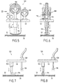
- Figures 5 and 6 schematically show a device 100 of removal of labels or self-adhesive discs 102, which is mounted on the carriage 52 supporting the cutting head, behind the cutting tool.
- the pads 102 are carried at regular intervals by a ribbon 104 unwound of a storage roller 106. After removing the pellets, the ribbon is taken up by a receiving roller 108.
- the rollers 106 and 108 are rotatably mounted in bearings supported by the carriage 52.
- the ribbon 104 carrying the pellets 102 is unwound from the roll 106 passing between two drive rollers 110 pressed one against the other and powered by a stepper motor 112.
- the latter controls intermittent advance of ribbon 104 with steps corresponding to that pellets 102 on the ribbon.
- the rewinding of the bare tape 104 on the roller 108 is provided by a motor (not shown) connected to the roller 108 by a torque limiter.
- the removal of the self-adhesive discs 102 on the film 32 is produced by means of an applicator 114.
- This consists of a jack the upper of which carries a sole 116 at its end over which the ribbon 104.
- the depositing device 100 is controlled by the computer 68 so as to deposit several pastilles 102 astride each contour cut from film 32.
- a deposition cycle involves lowering the applicator 114 for fixing a tablet by pressure on the surface of the film 32, raising the applicator 114 and advancing one step of the tape 104.
- the pads can be fixed at regular intervals or not the along the cut contour, as it is cut.
- the application a patch 102 on the film can be produced while the carriage 52 is at stopping, or on the fly, while the carriage 52 is moving. In this last In this case, it is preferable that the speed of the carriage is relatively reduced. To avoid penalizing the cutting speed with stops or slowdowns imposed on the carriage 52, it will be possible to choose to deposit pellets at times when, in the cutting cycle, the carriage 52 is stationary in X, Y or moves at low speed (interruption of the advance at the end of the contour or for passing an angle with change of brutal direction, or slower advance when cutting a delicate contour portion, for example a notch).
- the positioning of removal device immediately behind the tool allows it to track precisely the cut contour.
- Figure 7 shows another device 120 for forming fasteners localized, the latter performing a localized welding of the film overlapping the contour, under the effect of heat.
- the device 120 is mounted on the carriage 52 supporting the head of cutting, immediately behind the cutting tool. It includes a applicator 122 in the form of a jack, the rod of which carries, at its end, a crowbar 124, or sole, or heating punch. Welding is made by lowering the applicator 122 to bring the presser foot 124 in contact with the film 32.
- each fastener located along each cut contour, at regular or irregular intervals, each fastener preferably being formed when the cutting tool feed is interrupted or slowed down.
- a product having a function of welding promoter can be deposited on the film 32.
- the deposit is carried out over a certain width on either side of the cut contour, either continuously or at the locations provided for the fasteners achieve.
- the carriage 52 carries a spray nozzle 126 connected to a tank (not shown) by a flexible pipe provided a solenoid valve 128 controlled by the installation computer.
- the spray nozzle 126 is located between the cutting tool (not shown in Figure 7) and the applicator 122, or in front of the cutting tool.
- Figure 8 shows a device 130 for training continuous fasteners along the edges of the film parts cut.
- the device 130 is mounted on the carriage 52 supporting the head of cutting, immediately behind the cutting tool. It includes a applicator 132 in the form of a jack whose rod carries, at its end, a heating roller 134.
- the applicator 132 is supported by the carriage 52 by means of a rotary plate 135.
- the plate 135 is controlled in rotation about its vertical axis in synchronism with the turntable carrying the cutting tool.
- Welding is carried out by pressure exerted by the roller heating 134 on the film 32 under the action of the applicator.
- a product having a function of welding promoter can be placed on the film 32.
- the deposit is carried out over a certain width on either side of the cut contour, continuously.
- the carriage 52 carries a nozzle spray 136 connected to a reservoir (not shown) by a pipe flexible fitted with a solenoid valve 138 controlled by the installation.
- the spray nozzle is located in front of the applicator 132, in front of or behind the cutting tool.
- the device removal or formation of fasteners is carried by the carriage 52 for supporting the cutting head.
- this device is independent of the cutting head, which allows prevent the cutting speed from being affected by the laying or formation of attachments.
- Figures 9 and 10 show a device 140 designed to apply strips of adhesive film over the entire width of the mattress 30 covered by film 32, at the downstream end of the cutting table, before film peeling 32.
- the device 140 comprises a carriage 142 movable transversely, parallel to direction Y, along a beam 144 having a fixed position in direction X, immediately upstream of the deflector 74.
- the carriage 142 is guided by beam 144 and is engaged with a screw without end 144a parallel to the beam 144 and driven by a motor 146.
- the carriage 142 carries a clamp support 152 capable of coming into engagement laterally with the adhesive film 150 and a pressure roller 154.
- the clamp 152 is mounted on its support by being movable horizontally in direction Y between a retracted position and a gripping position, under the control of an actuator.
- the clamp 152 and the roller 154 are movable vertically between a raised position and a lowered position by being fixed to the ends of the rods of two respective actuators 152 a , 154 a .
- the adhesive film 150 passes successively between the blades of a cutting device 156 and under an applicator 158.
- the latter is formed by a roller movable vertically between a raised position and a lowered position by being fixed at the end of an actuator 158 a .
- a cycle for removing a transverse strip of adhesive film 150 includes the following operations.
- the clamp 152, the roller 154 and the applicator 158 being in the raised position, the clamp 152 unwinds the film 150, by engaging with the end thereof, by displacement of the carriage 142 in one direction (go) under the control of the motor 146.
- the clamp 152, the roller 154 and the applicator 158 are lowered to bring the adhesive film 150 into contact with the film 32.
- the clamp 152 is then open, retracted and raised and the movement of the carriage 142 is controlled in the other direction (return) by means of the 146. motor.
- the pressure roller in the lowered position applies the adhesive film strip on the film 32.
- the clamp 152 is brought into the gripping position to grasp the film 150 between the roller 148 and the cutting device 156. Then, the cutting device is activated, and the roller 154 and the applicator 158 have been identified. A new cycle can then be performed by moving the carriage 142 on its outward journey.
- Each strip of adhesive film is placed between two steps in advance of the mattress.
- the interval between strips in direction Y is chosen to ensure that each cut contour is covered by two strips at least. This interval can be regular, or adapted to dimensions of the different contours in direction Y.
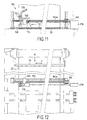
- Figures 11 and 12 show yet another mode of creation of a device for training localized attachments. As in the previous embodiment, this device 160 is carried by a carriage 162 separate from that supporting the cutting head.
- the carriage 162 is movable transversely, parallel to the direction Y, along a beam 164 having a fixed position in direction X, immediately upstream of the deflector 74.
- the carriage 162 is guided by the beam 164 and is engaged with an endless screw 164a parallel to the beam 164 and driven by a motor 166.
- the carriage 162 carries a projection nozzle 168 connected to a pressurized tank (not shown) containing a promoter material welding by a flexible pipe 170 provided with a solenoid valve 174.
- the carriage 162 carries a mirror 176 intended to reflect towards the surface of the film 32 a laser radiation produced by a generator 178 located in a side of the installation.
- the projection of the welding promoter material can be performed when the carriage 162 is moved in one direction in the Y direction while welding is carried out by heating by means of radiation laser by operating the generator when moving the carriage 162 in the other direction.
- Welding can be limited to areas of intersection between the contours and the X trajectory of the radiation laser, by corresponding modulation of the radiation produced by the generator.
- the intervals between welding lines are chosen, in the same way way that the intervals between strips of adhesive film in the example previous, so that each contour is cut by at least two lines welding.
- the heating for welding can be carried out not by projection of laser radiation, but by application of a heating element, for example a heating roller carried by the carriage 162.
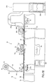
- a second embodiment of the invention is shown by the Figures 13 to 17. This embodiment differs from that of Figures 1 to 4 only by means of recovery of the film fragments in the downstream end area of the cutting table.
- the other elements of the installation are common to both modes of production. These common elements have the same reference and will not be described again in detail.
- the fragments of the sealing film 32 i.e. the skeleton 32 ' and the parts of film 32 "cut with the parts in the mattress 30, are taken by suction at the downstream end of the cutting table 20 at means of a movable member 200 to be released outside the path of the mattress and brought to an evacuation device 250.
- the movable member 200 shown in more detail in FIGS. 15 to 17, is in the form of a sectored annular hollow drum. It includes a hub 202, an outer wall 204 traversed by a plurality openings 206 and radial partitions 208 that extend all the way drum between the hub and the outer wall. Partitions 208 divide the drum into several sectors 210. These are among six in the example shown, but this number may be different.
- openings connect each sector with the outside, at the peripheral surface 205 of the drum, over the entire length of it.
- the openings 206 may be in the form of perforations or slots, for example circumferential slots extending over a part of the circumference of the drum, corresponding to each sector, as in the example illustrated.
- the sectors of the drum 200 are closed by annular flanges 212, 214 fixed to the drum.
- the drum 200 is mounted on an axis 216, the ends of which are engaged through plate openings 218, 220 forming bearings.
- the drum 200 is free to rotate about the axis 216.
- the evacuation device 250 comprises a tank or receptacle for reception 252 fixed to the plates 218, 220, immediately downstream of the drum 200.
- the tank 252 has a horizontal bottom wall 254, located substantially at the same level as that of the lower edges of the plates 218, 220.
- the wall 254 is folded back at its upstream end to form a rim 256 set back from the downstream generator 200b of the drum. At its downstream end, the wall 254 is folded back to form a downstream wall 258 of tank 252.
- the tank 252 is provided with side walls 260, 262. These are fixed on a tab 264 secured to the plates 218, 220 and support all of the longitudinal walls 254, 256, 258 of the tray.
- the device evacuation 250 may also include an extraction system by worm 270. This is fixed, with its drive motor 272, on one of the side walls 260 of the receiving tank 252. The fragments of sealing film recovered in the tank are extracted by the screw 270 to through an opening formed in the other side wall 262 and communicating, for example, with a chute 274.
- the plates 218, 220 supporting the drum 200 and the device 250 are pivotally mounted around a horizontal axis on supports 222, 224. These are fixed to the table frame cutting 20, on each side thereof. Pivots 226, 228 carried by the supports 222, 224 pass through openings in the plates 218, 220 located in the lower parts thereof. In this way, the whole comprising the drum 200 and the receiving tank 252, articulated on the supports 222, 224 rests by its weight on the mattress 30 coated with the film 32. As shown in FIG. 15, the lower generator 200a of the drum is lower than the lower edges of the plates 218, 220, so that the contact between the drum 200 and the mattress 30 is made only along the generator 200a.
- the rotation drive of the drum 200 with the flanges 212, 214 around the axis 216 is therefore produced by contact with the mattress 30 when this is advanced under the control of the motor 28 conveyor drive 22.
- the rotation drive of the drum 200 can be provided by a drive device, preferably disengageable, associated with an independent or driven motorization by means of the motor 28, in synchronism with the conveyor 22. Contact between the drum 200 and the mattress 30 is then not necessary, the surface of the drum can just flush with that of the mattress.
- the plate 218 which is in contact, practically free of play, with the flange 212 having two openings or lights 236, 238.
- Lines 240, 242 connect the lights 236, 238 ( Figure 15) respectively to a vacuum source and an air source under pressure (not shown).
- the slots 236 and 238 each extend along an arc with a central line located substantially on the same circumference as the centers of the openings 234 and a width substantially equal to the dimension of the openings 234.
- the slot 236 extends from a point 236 a located slightly downstream of the generator 200 a of the drum to a point 236 b located substantially at the level of the generator 200 b of the drum.
- the light 238 extends from a point 238 a located substantially at equal angular distance from the generator 200 b and from the upper generator 200 c of the drum to a point 238 b located substantially at the level of this generator 200 c .
- the angular position of the lights 236, 238 makes it possible to carry out a suction between the moment when the drum arrives near the mattress covered with the film and the moment when the drum overhangs the interior of the receiving tank 252 (the upstream wall 256 of the latter. ci being upstream of the downstream generator 200 b of the drum), and of producing a backflow after the suction until about the moment when the surface of the drum passes at the level of the upper generator 200 c .
- the fragments of film sucked up are well evacuated in the tank 252.
- the angular distance between points 236 b and 238 a of lights 236 and 238 is at least equal to the angular dimension of an opening 234, so that the same opening is not simultaneously opposite the lights 236, 238.
- L The maximum angular interval between the start of the discharge and the end of the discharge, or between the start of the suction and the end of the suction, determines the maximum angle of each sector and therefore the minimum number thereof. In practice, this minimum number is equal to 4, preferably to 5. It will also be noted that fragments of sealing film which may be of small dimensions, in certain cutting configurations, the density of the openings 206 on the surface of the drum must to be quite high. In the case of circumferential slots, as in the example illustrated, the pitch between slots is chosen between approximately 5 mm and 20 mm.
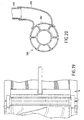
- FIGs 18 to 20 illustrate an alternative embodiment of the installation of Figures 13 to 17, the difference being in the form of realization of the evacuation device.
- the evacuation of the fragments of sealing film is made by transfer through a pipe outlet 290 between a receiving tank 280 and a recovery 292, the film fragments being for example collected in a carriage 294.
- the receiving tray 280 has a form of hood which opens at its lower part in close proximity to the surface of the drum 200.
- the opening 282 of the hood 280 extends substantially from immediately before the end of the suction zone until the end of the zone delivery (shown schematically in Figure 20).
- the fragments of sealing film collected in the hood 280 are propelled by pressurized air used for delivery, to reach the recovery device 292, through line 290.
Landscapes
- Life Sciences & Earth Sciences (AREA)
- Forests & Forestry (AREA)
- Engineering & Computer Science (AREA)
- Mechanical Engineering (AREA)
- Treatment Of Fiber Materials (AREA)
- Lining Or Joining Of Plastics Or The Like (AREA)
- Control Of Cutting Processes (AREA)
- Nonmetal Cutting Devices (AREA)
Description
procédé dans lequel au moins le squelette du film d'étanchéité est dévié du trajet de la matière en feuille dans une zone d'extrémité aval de la table pour être récupéré automatiquement, séparément des pièces découpées.
- la Figure 1 est une vue très schématique en élévation latérale d'un mode de réalisation d'une installation de coupe selon l'invention,
- la Figure 2 est une vue de dessus de l'installation de la Figure 1,
- la Figure 3 est une vue en élévation latérale montrant de façon plus détaillée la zone d'extrémité aval de la table de coupe de l'installation montrée par la Figure 1,
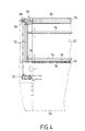
- la Figure 4 est une vue de face dans la direction A de la Figure 3,
- la Figure 5 est une vue partielle de détail d'un chariot tel que celui de l'installation de la Figure 1, portant un dispositif de dépôt d'attaches localisées, selon une première variante de réalisation de l'installation de la Figure 1,
- la Figure 6 est une vue en élévation de face du chariot de la figure 5,
- la Figure 7 est une vue partielle de détail d'un chariot tel que celui de l'installation de la figure 1, portant un dispositif de formation d'attaches localisées, selon une deuxième variante de réalisation de l'installation de la Figure 1,
- la Figure 8 est une vue partielle de détail d'un chariot tel que celui de l'installation de la figure 1, portant un dispositif de formation d'attaches continues, selon une troisième variante de réalisation de l'installation de la Figure 1,
- la Figure 9 est une vue en élévation illustrant un dispositif de pose de bande adhésive transversale selon une quatrième variante de réalisation de l'installation de la Figure 1,
- la Figure 10 est une vue de dessus du dispositif de pose de bande adhésive de la Figure 9,
- la Figure 11 est une vue en élévation illustrant un dispositif de formation de lignes de soudage transversales selon une cinquième variante de réalisation de l'installation de la Figure 1,
- la Figure 12 est une vue de dessus du dispositif de formation de lignes de soudage de la Figure 11,
- la Figure 13 est une vue schématique en élévation latérale d'un deuxième mode de réalisation d'une installation de coupe conforme à l'invention,
- la Figure 14 est une vue partielle de dessus de l'installation de la Figure 13,
- la Figure 15 est une vue de détail en élévation latérale à échelle agrandie du tambour de prélèvement et du réceptacle de récupération de fragments de film de l'installation de la Figure 13,
- la Figure 16 une vue partielle de dessus du tambour et du réceptacle de l'installation de la Figure 13, en coupe selon la ligne XVI-XVI de la Figure 15,
- la Figure 17 est une vue en coupe transversale du tambour de la Figure 15,
- la Figure 18 est une vue schématique en élévation latérale d'une variante de réalisation de l'installation de la Figure 13,
- la Figure 19 est une vue partielle de dessus de l'installation de la Figure 18, et
- la Figure 20 est une vue partielle de détail, à échelle agrandie, en élévation latérale et en coupe, du tambour de prélèvement et des moyens d'évacuation de l'installation de la Figure 18.
Claims (47)
- Procédé de coupe automatique de matière en feuille (30) du type comprenant l'amenée d'au moins un pli de matière en feuille (30) sur une table de coupe (20), le maintien de la matière en feuille (30) sur la table (20) par dépression, l'application d'un film d'étanchéité (32) sur la surface de la matière en feuille (30), la découpe de pièces de formes prédéterminées au moyen d'un outil (60) traversant le film d'étanchéité (32) et la matière en feuille (30), l'évacuation de pièces découpées en aval de la table de coupe (20).
caractérisé en ce qu'au moins le squelette (32') du film d'étanchéité (32) est dévié du trajet de la matière en feuille (30) dans une zone d'extrémité aval de la table (20) pour être récupéré automatiquement, séparément des pièces découpées. - Procédé selon la revendication 1, caractérisé en ce qu'au moins le squelette (32') du film d'étanchéité (32) est récupéré par ré-enroulement automatique.
- Procédé selon la revendication 2, caractérisé en ce que le ré-enroulement est effectué par appel sur un mandrin (70) à une vitesse tangentielle asservie à la vitesse de déplacement de la matière en feuille (30) sur la table de coupe (20).
- Procédé selon l'une quelconque des revendications 1 à 3, caractérisé en ce que la découpe des pièces est réalisée en conservant l'intégrité du squelette (32') du film d'étanchéité (32).
- Procédé selon l'une quelconque des revendications 1 à 4, caractérisé en ce qu'il comprend la dépose ou formation d'attaches reliant au squelette (32') du film d'étanchéité (32) au moins certaines parties (32'') du film d'étanchéité découpées avec les pièces.
- Procédé selon la revendication 5, caractérisé en ce qu'il comprend la dépose ou formation d'attaches reliant au squelette (32') du film d'étanchéité (32) chacune des parties (32") du film d'étanchéité (32) découpées avec les pièces dans la matière en feuille (30), de manière à récupérer un film étanche (32) sensiblement reconstitué.
- Procédé selon l'une quelconque des revendications 5 et 6, caractérisé en ce que l'on dépose des attaches sous forme d'éléments autocollants (102) le long des contours des parties (32") du film d'étanchéité (32) découpées avec les pièces.
- Procédé selon l'une quelconque des revendications 5 et 6, caractérisé en ce que l'on forme des attaches par soudage du film d'étanchéité le long des contours des parties du film d'étanchéité (32) découpées avec les pièces.
- Procédé selon la revendication 8, caractérisé en ce que, préalablement au soudage, un matériau promoteur du soudage est déposé sur le film d'étanchéité (32).
- Procédé selon l'une quelconque des revendications 8 et 9, caractérisé en ce que le soudage est réalisé par application d'un élément chauffant (124, 134).
- Procédé selon l'une quelconque des revendications 8 et 9, caractérisé en ce que le soudage est réalisé par projection d'un rayonnement laser.
- Procédé selon l'une quelconque des revendications 5 à 11, caractérisé en ce que les attaches sont réalisées de façon localisée en différents emplacements le long des contours des parties (32") du film d'étanchéité (32) découpées avec les pièces.
- Procédé selon l'une quelconque des revendications 5 à 11, caractérisé en ce que les attaches sont réalisées de façon continue le long des contours des parties (32") du film d'étanchéité (32) découpées avec les pièces.
- Procédé selon l'une quelconque des revendications 5 à 13, caractérisé en ce que la dépose ou formation d'attaches est réalisée immédiatement après la découpe, en suivant le trajet de l'outil de coupe (60).
- Procédé selon l'une quelconque des revendications 5 et 6, caractérisé en ce que l'on forme des attaches localisées par fixation de bandelettes de film adhésif (150) sur le film d'étanchéité (32), en direction transversale par rapport au trajet de la matière en feuille (30), après découpe des pièces et avant déviation du film d'étanchéité (32) par rapport au trajet de la matière en feuille (30).
- Procédé selon l'une quelconque des revendications 8 à 11, caractérisé en ce que l'on forme des attaches localisées sous forme de lignes de soudage en direction transversale par rapport au trajet de la matière en feuille (30), après découpe des pièces et avant déviation du film d'étanchéité (32) par rapport au trajet de la matière en feuille (30).
- Procédé selon la revendication 1, caractérisé en ce que des fragments du film d'étanchéité (32) constitués par le squelette (32') et des parties (32'') du film découpées avec les pièces sont prélevés par aspiration hors du trajet de la matière en feuille (30) puis évacués.
- Procédé selon la revendication 17, caractérisé en ce que le prélèvement des fragments de film est réalisé au moyen d'un organe mobile (200) adjacent au trajet de la matière en feuille.
- Procédé selon la revendication18, caractérisé en ce que l'organe mobile (200) est entraíné en rotation par contact avec la matière en feuille (30) et avance de celle-ci.
- Procédé selon l'une quelconque des revendications 18 et 19, caractérisé en ce que l'on utilise un organe mobile rotatif (200) comprenant plusieurs secteurs (210) et une dépression est établie dans chaque secteur (210) pendant le déplacement de celui-ci entre un emplacement situé à la proximité du trajet de la matière en feuille (30) et une zone d'évacuation de fragments de film (32).
- Procédé selon la revendication 20, caractérisé en ce qu'une surpression est établie dans chaque secteur (21b) lorsqu'il parvient dans la zone d'évacuation.
- Procédé selon l'une quelconque des revendications 17 à 21, caractérisé en ce que les fragments de film (32) sont évacués par dépôt dans un réceptacle (252) situé au-dessus du trajet de la matière en feuille (30) et par extraction hors du réceptacle.
- Procédé selon l'une quelconque des revendications 17 à 22, caractérisé en ce que les fragments de film (32) sont évacués en étant amenés à un conduit d'évacuation (290).
- Procédé selon l'une quelconque des revendications 1 à 16, caractérisé en ce que le film d'étanchéité (32) est étalé sur la matière en feuille (30).
- Installation de coupe automatique de matière en feuille, comprenant une table de coupe (20), un poste (12) de chargement de matière en feuille à découper à une extrémité amont de la table de coupe (20), un poste (16) de déchargement de pièces découpées à une extrémité aval de la table de coupe, des moyens (24, 26) d'établissement d'une dépression à la surface de la table de coupe, et des moyens (34, 40, 42) d'amenée d'un film d'étanchéité souple (32) au voisinage de l'extrémité amont de la table de coupe (20),
caractérisée en ce qu'elle comporte en outre des moyens (74, 70, 200, 250, 280) pour séparer au moins un squelette (32') de film d'étanchéité (32) du trajet de la matière en feuille au voisinage de l'extrémité aval de la table de coupe (20) et pour le récupérer automatiquement hors du poste (16) de déchargement de pièces découpées. - Installation selon la revendication 25, caractérisée en ce qu'elle comprend des moyens (70) d'enroulement d'au moins le squelette (32') du film d'étanchéité (32).
- Installation selon la revendication 26, comprenant des moyens (28) d'avance de la matière en feuille (30) sur la table de coupe (20), caractérisée en ce que les moyens d'enroulement (70) sont reliés aux moyens d'avance (28) par une liaison mécanique (80) destinée à asservir la vitesse tangentielle d'enroulement à la vitesse d'avance sur la table de coupe (20).
- Installation selon la revendication 26, comprenant des moyens (28) d'avance de la matière en feuille (30) sur la table de coupe (20), caractérisée en ce que les moyens d'enroulement (70) comportent un moteur particulier dont la commande est asservie à la vitesse d'avance sur la table de coupe (20).
- Installation selon l'une quelconque des revendications 18 à 28, caractérisée en ce qu'elle comprend un dispositif (100; 120; 130; 140; 160) de dépose ou formation d'attaches à la surface du film d'étanchéité (32), sur la table de coupe (20).
- Installation selon la revendication 29, caractérisée en ce que le dispositif (120 ; 130 ; 160) de formation d'attaches comprend des moyens de soudage (124, 134, 176, 178) du film d'étanchéité (32).
- Installation selon la revendication 30, caractérisée en ce que les moyens de soudage comportent un élément chauffant (124 ; 134) et des moyens (122 ; 132) d'application de l'élément chauffant (124, 134) à la surface du film d'étanchéité (32).
- Installation selon la revendication 31, comprenant une tête de coupe (50) montée sur un chariot (52) mobile au-dessus de la table de coupe (20), caractérisée en ce que l'élément chauffant (124, 134) est monté sur ledit chariot (52).
- Installation selon la revendication 29, caractérisée en ce que les moyens de soudage (176, 178) comportent des moyens (176) de projection d'un rayonnement laser à la surface du film d'étanchéité (32).
- Installation selon l'une quelconque des revendications 30 à 33, caractérisée en ce qu'elle comporte des moyens de projection (126, 136, 168) d'un matériau promoteur de soudage à la surface du film d'étanchéité (32).
- Installation selon la revendication 29, caractérisée en ce que le dispositif (100 ; 140) de pose d'attaches comprend des moyens d'application (116, 154) d'éléments adhésifs (102) sur le film d'étanchéité (32).
- Installation selon la revendication 35, caractérisée en ce que le dispositif (100) de pose d'attaches comprend des moyens d'application (116) de pastilles autocollantes (102).
- Installation selon la revendication 36, comprenant une tête de coupe (50) montée sur un chariot (52) mobile au-dessus de la table de coupe (20), caractérisée en ce que les moyens d'application de pastilles autocollantes (102) sont portés par ledit chariot (52).
- Installation selon la revendication 35, caractérisée en ce que le dispositif (140) de pose d'attaches comprend des moyens d'application (154) de bandelettes de film adhésif (150) en direction transversale par rapport à l'avance de la matière souple en feuille (30).
- Installation selon la revendication 25, caractérisée en ce qu'elle comporte des moyens (200) de prélèvement par aspiration de fragments de film d'étanchéité, au voisinage de l'extrémité aval de la table de coupe, et des moyens (250; 280) d'évacuation de fragments de film prélevés.
- Installation selon la revendication 39, caractérisée en ce que les moyens (200) de prélèvement par aspiration comportent un tambour rotatif (200) ayant plusieurs secteurs (210) qui communiquent avec l'extérieur à travers des orifices s'ouvrant à la surface du tambour, et des moyens (236, 240) de mise en dépression des secteurs sur une partie de leur trajet en rotation entre un emplacement situé à proximité du plan de la table de coupe (20) et un emplacement situé à proximité des moyens (250; 280) d'évacuation de fragments de film (32).
- Installation selon la revendication 40, caractérisée en ce que le tambour (200) est adjacent à au moins l'une de ses extrémités axiales à une platine fixe (218) munie d'au moins un orifice (236) de raccordement à une source de vide.
- Installation selon l'une quelconque des revendications 40 et 41, caractérisée en ce qu'elle comporte en outre des moyens (238, 242) de mise en surpression des secteurs sur une partie de leur trajet en rotation, au moins au niveau des moyens d'évacuation (250; 280).
- Installation selon la revendication 42, caractérisée en ce que le tambour (200) est adjacent à au moins l'une de ses extrémités axiales à une platine fixe (218) munie d'au moins un orifice (238) de raccordement à une source d'air sous pression.
- Installation selon l'une quelconque des revendications 40 à 43, caractérisée en ce que le tambour (200) est monté libre en rotation, de sorte que l'entraínement en rotation du tambour est réalisé par contact avec sa surface.
- Installation selon l'une quelconque des revendications 39 à 44, caractérisée en ce que les moyens (250, 280) d'évacuation de fragments de film comportent un bac (252) situé au dessus du plan de la table de coupe (20) et des moyens (270) d'extraction de fragments de film hors du réceptacle.
- Installation selon l'une quelconque des revendications 39 à 44, caractérisée en ce que les moyens d'évacuation (250, 280) de fragments de film comportent une conduite (280, 290) qui se raccorde à une ouverture (282) située au-dessus du plan de la table de coupe (20) pour recueillir les fragments de film aspiré (32).
- Installation selon l'une quelconque des revendications 25 à 46, caractérisée en ce qu'elle comprend des moyens (40) d'étalement du film étanche (32) sur la matière en feuille (30).
Applications Claiming Priority (3)
| Application Number | Priority Date | Filing Date | Title |
|---|---|---|---|
| FR9811541A FR2783191B1 (fr) | 1998-09-16 | 1998-09-16 | Coupe automatique de pieces dans une matiere en feuille |
| FR9811541 | 1998-09-16 | ||
| PCT/FR1999/002206 WO2000015397A1 (fr) | 1998-09-16 | 1999-09-16 | Coupe automatique de pieces dans une matiere en feuille |
Publications (2)
| Publication Number | Publication Date |
|---|---|
| EP1045746A1 EP1045746A1 (fr) | 2000-10-25 |
| EP1045746B1 true EP1045746B1 (fr) | 2002-07-17 |
Family
ID=9530482
Family Applications (1)
| Application Number | Title | Priority Date | Filing Date |
|---|---|---|---|
| EP99942987A Expired - Lifetime EP1045746B1 (fr) | 1998-09-16 | 1999-09-16 | Coupe automatique de pieces dans une matiere en feuille |
Country Status (6)
| Country | Link |
|---|---|
| US (2) | US6521074B1 (fr) |
| EP (1) | EP1045746B1 (fr) |
| DE (1) | DE69902140T2 (fr) |
| ES (1) | ES2179673T3 (fr) |
| FR (1) | FR2783191B1 (fr) |
| WO (1) | WO2000015397A1 (fr) |
Cited By (2)
| Publication number | Priority date | Publication date | Assignee | Title |
|---|---|---|---|---|
| CN103948198A (zh) * | 2014-03-28 | 2014-07-30 | 湖北欣意无纺布特种制品有限公司 | 无纺布y型腰带自动制造机 |
| EP4126483B1 (fr) * | 2020-03-26 | 2023-08-23 | Gerber Technology LLC | Appareil de tendeur de feuille de recouvrement |
Families Citing this family (19)
| Publication number | Priority date | Publication date | Assignee | Title |
|---|---|---|---|---|
| FR2783191B1 (fr) * | 1998-09-16 | 2000-12-15 | Lectra Systemes Sa | Coupe automatique de pieces dans une matiere en feuille |
| AU2003281780A1 (en) * | 2002-06-26 | 2004-02-16 | Gerber Technology, Inc. | Method and apparatus for making a laminate |
| JP4451739B2 (ja) * | 2004-07-30 | 2010-04-14 | 株式会社島精機製作所 | 吸引式載置台のシール装置 |
| USD575329S1 (en) | 2005-05-06 | 2008-08-19 | Kontrelmec, S.L. | Manufacturing and handling machine for labels |
| DE602005014223D1 (de) | 2005-07-15 | 2009-06-10 | Emanuela Guerriero | Methode zum Auslegen und Schneiden von biegeschlaffem Bahnmaterial |
| CA2561465A1 (fr) * | 2006-09-25 | 2008-03-25 | David Crowther | Dispositif de retenue de pieces a travailler par pression sous vide pour scie |
| US7284305B1 (en) | 2007-01-12 | 2007-10-23 | Milliken & Company | Apparatus and process for automatically cutting textile web with reduced wrinkling |
| KR100934462B1 (ko) * | 2007-07-04 | 2009-12-30 | 주식회사 엘지화학 | 높은 재단 효율성의 재단 프레임 |
| KR100948969B1 (ko) * | 2007-07-16 | 2010-03-23 | 주식회사 엘지화학 | 높은 재단 효율성으로 직사각형 단위체들을 제조하는 방법 |
| ES2346621B1 (es) * | 2008-12-23 | 2011-08-03 | Airbus Operations, S.L. | Procedimiento y dispositivo para la obtencion de piezas longitudinales. |
| ITMI20090268A1 (it) * | 2009-02-25 | 2010-08-26 | Ohg Molina E Bianch I S P A | Apparecchiatura per il taglio di materiale in fogli |
| ITMI20110931A1 (it) * | 2011-05-24 | 2012-11-25 | Orox S R L | Macchina automatica da taglio per materiale in fogli |
| US20160023791A1 (en) * | 2014-07-25 | 2016-01-28 | Eminence Machinery Co., Ltd. | Sealing Device for Automatic Bagging Machine |
| FR3060432B1 (fr) | 2016-12-16 | 2019-05-24 | Lectra | Procede de partitionnement d'un placement predetermine de pieces destinees a etre decoupees dans un materiau souple en feuille |
| CN107584225A (zh) * | 2017-11-03 | 2018-01-16 | 青岛海镭激光科技有限公司 | 一种玻璃码盘加工取料装置 |
| CN113664293A (zh) * | 2021-08-26 | 2021-11-19 | 中国核电工程有限公司 | 一种切割装置及密封系统 |
| US20230081765A1 (en) * | 2021-09-10 | 2023-03-16 | Chun-Fu Kuo | Processing device for processing opposing edges of a flexible sheet body |
| IT202200013096A1 (it) * | 2022-06-21 | 2023-12-21 | Fk Group S P A | Macchina per il taglio automatico di pezzi piani e relativo metodo |
| KR102697959B1 (ko) * | 2024-02-06 | 2024-08-22 | 주식회사 유진컴퍼니 | 맞춤형 인조가죽 재단을 위한 평탄화 및 재단 장치 |
Family Cites Families (11)
| Publication number | Priority date | Publication date | Assignee | Title |
|---|---|---|---|---|
| US3682750A (en) * | 1969-12-09 | 1972-08-08 | Gerber Garment Technology Inc | Cutting apparatus with vacuum hold-down and cut sealing means |
| US3882750A (en) * | 1974-07-22 | 1975-05-13 | Dayco Corp | Rotary anvil construction |
| DE2819441C2 (de) * | 1978-05-03 | 1987-04-23 | Günter O. 7421 Mehrstetten Stumpf | Stoffzuschneidemaschine |
| AT394515B (de) * | 1989-02-21 | 1992-04-27 | Gfm Holding Ag | Schneidanlage zum ausschneiden von zuschnitten aus bandmaterial |
| US4999081A (en) * | 1989-10-11 | 1991-03-12 | Float Machines Inc. | Cutting and heat sealing die assembly |
| US5101747A (en) * | 1989-12-19 | 1992-04-07 | Gerber Garment Technology, Inc. | Apparatus and method for separating pattern pieces from waste material |
| DE4204756A1 (de) * | 1992-02-18 | 1993-05-13 | Wuestenberg Dieter Prof Dr Ing | Verfahren zur kontinuierlichen bzw. abschnittsweise kontinuierlichen raeumlichen trennung textiler gutteilstapel und dem sie umgebenden abfall |
| FR2707545B1 (fr) | 1993-07-15 | 1995-10-20 | Lectra Systemes Sa | Procédé pour l'exécution de tracés ou découpes suivant des trajectoires prédéterminées sur un matériau. |
| DE4344814A1 (de) * | 1993-12-28 | 1995-06-29 | Bullmer Spezialmaschinen Gmbh | Zuschneidevorrichtung mit Schnittfugenabdichtung |
| US6050164A (en) * | 1998-07-15 | 2000-04-18 | Gerber Technology, Inc. | Adjustable resealer |
| FR2783191B1 (fr) * | 1998-09-16 | 2000-12-15 | Lectra Systemes Sa | Coupe automatique de pieces dans une matiere en feuille |
-
1998
- 1998-09-16 FR FR9811541A patent/FR2783191B1/fr not_active Expired - Fee Related
-
1999
- 1999-09-16 ES ES99942987T patent/ES2179673T3/es not_active Expired - Lifetime
- 1999-09-16 WO PCT/FR1999/002206 patent/WO2000015397A1/fr not_active Ceased
- 1999-09-16 EP EP99942987A patent/EP1045746B1/fr not_active Expired - Lifetime
- 1999-09-16 DE DE69902140T patent/DE69902140T2/de not_active Expired - Lifetime
- 1999-09-16 US US09/554,523 patent/US6521074B1/en not_active Expired - Lifetime
-
2002
- 2002-12-20 US US10/324,606 patent/US7024976B2/en not_active Expired - Lifetime
Cited By (2)
| Publication number | Priority date | Publication date | Assignee | Title |
|---|---|---|---|---|
| CN103948198A (zh) * | 2014-03-28 | 2014-07-30 | 湖北欣意无纺布特种制品有限公司 | 无纺布y型腰带自动制造机 |
| EP4126483B1 (fr) * | 2020-03-26 | 2023-08-23 | Gerber Technology LLC | Appareil de tendeur de feuille de recouvrement |
Also Published As
| Publication number | Publication date |
|---|---|
| DE69902140T2 (de) | 2003-03-20 |
| ES2179673T3 (es) | 2003-01-16 |
| US6521074B1 (en) | 2003-02-18 |
| EP1045746A1 (fr) | 2000-10-25 |
| FR2783191A1 (fr) | 2000-03-17 |
| DE69902140D1 (de) | 2002-08-22 |
| US7024976B2 (en) | 2006-04-11 |
| WO2000015397A1 (fr) | 2000-03-23 |
| FR2783191B1 (fr) | 2000-12-15 |
| US20030121610A1 (en) | 2003-07-03 |
Similar Documents
| Publication | Publication Date | Title |
|---|---|---|
| EP1045746A1 (fr) | Coupe automatique de pieces dans une matiere en feuille | |
| EP1105262B1 (fr) | Procede et installation pour la decoupe et le dechargement automatique de piles de pieces dans un matelas de matiere en feuille | |
| EP3248920B1 (fr) | Procédé de coupe et de raccordement de deux bandes bout à bout et à l arrêt dans une machine à dérouler, dispositif de coupe et de raccordement et machine équipée d'un tel dispositif permettant la mise en oeuvre dudit procédé | |
| EP2146828B1 (fr) | Dispositif de separation et d'evacuation des chutes decoupees dans une bande de preimpregne | |
| EP2429781B1 (fr) | Unité d'éjection des déchets à réglage d'outil facilité dans une machine de production d'emballages | |
| FR2612879A1 (fr) | Appareil d'alimentation en un materiau sous forme de film | |
| JPH05502848A (ja) | ウエブをコアに巻く際にウエブの先端及び後端を貼り付ける方法及び装置 | |
| EP2112106B1 (fr) | Procédé et dispositif de coupe et de collage bout à bout pour machine à dérouler | |
| CA1102080A (fr) | Machine automatique pour le tronconnage de gaine thermoplastique | |
| FR2674788A1 (fr) | Procede de coupe interrompue d'une ligne dans un materiau en feuille. | |
| EP2152500A2 (fr) | Tête de drapage de composite avec dispositif escamotable de séparation de préimprégné de son ruban de support | |
| EP2196293B1 (fr) | Machine de découpe de décors pour des supports tronconiques et ensemble de formage de supports tronconiques et de pose de décors, comportant une telle machine de découpe | |
| EP0963320B1 (fr) | Stockage de pieces decoupees dans un matelas | |
| CH661910A5 (fr) | Procede et dispositif pour la separation et le transport de pieces de tissu. | |
| FR2620073A1 (fr) | Machine pour la decoupe de pieces dans une bande de matiere et pour la jonction des pieces qui viennent d'etre decoupees | |
| FR2626209A1 (fr) | Machine de decoupe de matiere en bande par jets fluides haute pression | |
| CH714352A1 (fr) | Machine pour le recyclage des pneus. | |
| EP0298792B1 (fr) | Dispositif pour appliquer une pellicule de protection sur une plaque alvéolaire | |
| FR2754240A1 (fr) | Dispositif d'application de bandes de dechirement | |
| EP4330006B1 (fr) | Procédé et installation perfectionnés d'enroulage en continu de bandelettes de gomme pour former des galettes | |
| BE823679A (fr) | Machine a former des sacs en matiere plastique | |
| EP1074497B1 (fr) | Procédé et installation pour rabouter les extrémités de materiaux en bandes, bandes textiles notamment | |
| EP1037843B1 (fr) | Procede de decoupage d'affiches et dispositif pour sa mise en oeuvre | |
| EP0002538A2 (fr) | Procédé pour la fabrication de liasses de sacs et machine pour la mise en oeuvre de ce procédé | |
| FR2731942A1 (fr) | Procede et installation de fabrication d'emballages en materiau plastique et emballage obtenu |
Legal Events
| Date | Code | Title | Description |
|---|---|---|---|
| PUAI | Public reference made under article 153(3) epc to a published international application that has entered the european phase |
Free format text: ORIGINAL CODE: 0009012 |
|
| AK | Designated contracting states |
Kind code of ref document: A1 Designated state(s): AT BE CH CY DE DK ES FI FR GB GR IE IT LI LU MC NL PT SE |
|
| 17P | Request for examination filed |
Effective date: 20000912 |
|
| GRAG | Despatch of communication of intention to grant |
Free format text: ORIGINAL CODE: EPIDOS AGRA |
|
| 17Q | First examination report despatched |
Effective date: 20010516 |
|
| GRAG | Despatch of communication of intention to grant |
Free format text: ORIGINAL CODE: EPIDOS AGRA |
|
| GRAG | Despatch of communication of intention to grant |
Free format text: ORIGINAL CODE: EPIDOS AGRA |
|
| GRAH | Despatch of communication of intention to grant a patent |
Free format text: ORIGINAL CODE: EPIDOS IGRA |
|
| RAP1 | Party data changed (applicant data changed or rights of an application transferred) |
Owner name: LECTRA SA |
|
| GRAH | Despatch of communication of intention to grant a patent |
Free format text: ORIGINAL CODE: EPIDOS IGRA |
|
| GRAA | (expected) grant |
Free format text: ORIGINAL CODE: 0009210 |
|
| AK | Designated contracting states |
Kind code of ref document: B1 Designated state(s): DE ES FR GB IT |
|
| PG25 | Lapsed in a contracting state [announced via postgrant information from national office to epo] |
Ref country code: GB Free format text: LAPSE BECAUSE OF FAILURE TO SUBMIT A TRANSLATION OF THE DESCRIPTION OR TO PAY THE FEE WITHIN THE PRESCRIBED TIME-LIMIT Effective date: 20020717 |
|
| REG | Reference to a national code |
Ref country code: GB Ref legal event code: FG4D Free format text: NOT ENGLISH |
|
| REF | Corresponds to: |
Ref document number: 69902140 Country of ref document: DE Date of ref document: 20020822 |
|
| REG | Reference to a national code |
Ref country code: ES Ref legal event code: FG2A Ref document number: 2179673 Country of ref document: ES Kind code of ref document: T3 |
|
| GBT | Gb: translation of ep patent filed (gb section 77(6)(a)/1977) |
Effective date: 20030206 |
|
| PLBE | No opposition filed within time limit |
Free format text: ORIGINAL CODE: 0009261 |
|
| STAA | Information on the status of an ep patent application or granted ep patent |
Free format text: STATUS: NO OPPOSITION FILED WITHIN TIME LIMIT |
|
| 26N | No opposition filed |
Effective date: 20030422 |
|
| REG | Reference to a national code |
Ref country code: FR Ref legal event code: PLFP Year of fee payment: 18 |
|
| REG | Reference to a national code |
Ref country code: DE Ref legal event code: R082 Ref document number: 69902140 Country of ref document: DE Representative=s name: SCHMITT-NILSON SCHRAUD WAIBEL WOHLFROM PATENTA, DE |
|
| REG | Reference to a national code |
Ref country code: FR Ref legal event code: PLFP Year of fee payment: 19 |
|
| REG | Reference to a national code |
Ref country code: FR Ref legal event code: PLFP Year of fee payment: 20 |
|
| PGFP | Annual fee paid to national office [announced via postgrant information from national office to epo] |
Ref country code: IT Payment date: 20180828 Year of fee payment: 20 Ref country code: DE Payment date: 20180821 Year of fee payment: 20 Ref country code: FR Payment date: 20180822 Year of fee payment: 20 |
|
| PGFP | Annual fee paid to national office [announced via postgrant information from national office to epo] |
Ref country code: GB Payment date: 20180823 Year of fee payment: 20 |
|
| PGFP | Annual fee paid to national office [announced via postgrant information from national office to epo] |
Ref country code: ES Payment date: 20181001 Year of fee payment: 20 |
|
| REG | Reference to a national code |
Ref country code: DE Ref legal event code: R071 Ref document number: 69902140 Country of ref document: DE |
|
| REG | Reference to a national code |
Ref country code: GB Ref legal event code: PE20 Expiry date: 20190915 |
|
| PG25 | Lapsed in a contracting state [announced via postgrant information from national office to epo] |
Ref country code: GB Free format text: LAPSE BECAUSE OF EXPIRATION OF PROTECTION Effective date: 20190915 |
|
| REG | Reference to a national code |
Ref country code: ES Ref legal event code: FD2A Effective date: 20200724 |
|
| PG25 | Lapsed in a contracting state [announced via postgrant information from national office to epo] |
Ref country code: ES Free format text: LAPSE BECAUSE OF EXPIRATION OF PROTECTION Effective date: 20190917 |