EP1045954B1 - Flachfederantrieb und fensterabdeckung - Google Patents
Flachfederantrieb und fensterabdeckung Download PDFInfo
- Publication number
- EP1045954B1 EP1045954B1 EP98956605A EP98956605A EP1045954B1 EP 1045954 B1 EP1045954 B1 EP 1045954B1 EP 98956605 A EP98956605 A EP 98956605A EP 98956605 A EP98956605 A EP 98956605A EP 1045954 B1 EP1045954 B1 EP 1045954B1
- Authority
- EP
- European Patent Office
- Prior art keywords
- spring
- blind
- flat spring
- spring drive
- drive
- Prior art date
- Legal status (The legal status is an assumption and is not a legal conclusion. Google has not performed a legal analysis and makes no representation as to the accuracy of the status listed.)
- Expired - Lifetime
Links
- 230000005540 biological transmission Effects 0.000 claims abstract description 67
- 230000006835 compression Effects 0.000 abstract description 20
- 238000007906 compression Methods 0.000 abstract description 20
- 230000001965 increasing effect Effects 0.000 description 17
- 230000007423 decrease Effects 0.000 description 11
- 230000003247 decreasing effect Effects 0.000 description 10
- 239000000463 material Substances 0.000 description 5
- 230000000694 effects Effects 0.000 description 3
- 230000001413 cellular effect Effects 0.000 description 2
- 230000003292 diminished effect Effects 0.000 description 2
- 239000004744 fabric Substances 0.000 description 2
- 239000002184 metal Substances 0.000 description 2
- 229910000831 Steel Inorganic materials 0.000 description 1
- 230000006978 adaptation Effects 0.000 description 1
- 238000000418 atomic force spectrum Methods 0.000 description 1
- 239000000969 carrier Substances 0.000 description 1
- 210000003850 cellular structure Anatomy 0.000 description 1
- 238000010276 construction Methods 0.000 description 1
- 238000005034 decoration Methods 0.000 description 1
- 230000002708 enhancing effect Effects 0.000 description 1
- 238000009434 installation Methods 0.000 description 1
- 230000013011 mating Effects 0.000 description 1
- 230000007246 mechanism Effects 0.000 description 1
- 238000000034 method Methods 0.000 description 1
- 239000012858 resilient material Substances 0.000 description 1
- 239000010959 steel Substances 0.000 description 1
- 239000013589 supplement Substances 0.000 description 1
Images



Classifications
-
- E—FIXED CONSTRUCTIONS
- E06—DOORS, WINDOWS, SHUTTERS, OR ROLLER BLINDS IN GENERAL; LADDERS
- E06B—FIXED OR MOVABLE CLOSURES FOR OPENINGS IN BUILDINGS, VEHICLES, FENCES OR LIKE ENCLOSURES IN GENERAL, e.g. DOORS, WINDOWS, BLINDS, GATES
- E06B9/00—Screening or protective devices for wall or similar openings, with or without operating or securing mechanisms; Closures of similar construction
- E06B9/24—Screens or other constructions affording protection against light, especially against sunshine; Similar screens for privacy or appearance; Slat blinds
- E06B9/26—Lamellar or like blinds, e.g. venetian blinds
- E06B9/28—Lamellar or like blinds, e.g. venetian blinds with horizontal lamellae, e.g. non-liftable
- E06B9/30—Lamellar or like blinds, e.g. venetian blinds with horizontal lamellae, e.g. non-liftable liftable
-
- E—FIXED CONSTRUCTIONS
- E06—DOORS, WINDOWS, SHUTTERS, OR ROLLER BLINDS IN GENERAL; LADDERS
- E06B—FIXED OR MOVABLE CLOSURES FOR OPENINGS IN BUILDINGS, VEHICLES, FENCES OR LIKE ENCLOSURES IN GENERAL, e.g. DOORS, WINDOWS, BLINDS, GATES
- E06B9/00—Screening or protective devices for wall or similar openings, with or without operating or securing mechanisms; Closures of similar construction
- E06B9/24—Screens or other constructions affording protection against light, especially against sunshine; Similar screens for privacy or appearance; Slat blinds
- E06B9/26—Lamellar or like blinds, e.g. venetian blinds
- E06B9/28—Lamellar or like blinds, e.g. venetian blinds with horizontal lamellae, e.g. non-liftable
- E06B9/30—Lamellar or like blinds, e.g. venetian blinds with horizontal lamellae, e.g. non-liftable liftable
- E06B9/32—Operating, guiding, or securing devices therefor
- E06B9/322—Details of operating devices, e.g. pulleys, brakes, spring drums, drives
-
- E—FIXED CONSTRUCTIONS
- E06—DOORS, WINDOWS, SHUTTERS, OR ROLLER BLINDS IN GENERAL; LADDERS
- E06B—FIXED OR MOVABLE CLOSURES FOR OPENINGS IN BUILDINGS, VEHICLES, FENCES OR LIKE ENCLOSURES IN GENERAL, e.g. DOORS, WINDOWS, BLINDS, GATES
- E06B9/00—Screening or protective devices for wall or similar openings, with or without operating or securing mechanisms; Closures of similar construction
- E06B9/56—Operating, guiding or securing devices or arrangements for roll-type closures; Spring drums; Tape drums; Counterweighting arrangements therefor
- E06B9/60—Spring drums operated only by closure members
-
- E—FIXED CONSTRUCTIONS
- E06—DOORS, WINDOWS, SHUTTERS, OR ROLLER BLINDS IN GENERAL; LADDERS
- E06B—FIXED OR MOVABLE CLOSURES FOR OPENINGS IN BUILDINGS, VEHICLES, FENCES OR LIKE ENCLOSURES IN GENERAL, e.g. DOORS, WINDOWS, BLINDS, GATES
- E06B9/00—Screening or protective devices for wall or similar openings, with or without operating or securing mechanisms; Closures of similar construction
- E06B9/56—Operating, guiding or securing devices or arrangements for roll-type closures; Spring drums; Tape drums; Counterweighting arrangements therefor
- E06B9/62—Counterweighting arrangements
-
- E—FIXED CONSTRUCTIONS
- E06—DOORS, WINDOWS, SHUTTERS, OR ROLLER BLINDS IN GENERAL; LADDERS
- E06B—FIXED OR MOVABLE CLOSURES FOR OPENINGS IN BUILDINGS, VEHICLES, FENCES OR LIKE ENCLOSURES IN GENERAL, e.g. DOORS, WINDOWS, BLINDS, GATES
- E06B9/00—Screening or protective devices for wall or similar openings, with or without operating or securing mechanisms; Closures of similar construction
- E06B9/56—Operating, guiding or securing devices or arrangements for roll-type closures; Spring drums; Tape drums; Counterweighting arrangements therefor
- E06B9/80—Safety measures against dropping or unauthorised opening; Braking or immobilising devices; Devices for limiting unrolling
- E06B9/82—Safety measures against dropping or unauthorised opening; Braking or immobilising devices; Devices for limiting unrolling automatic
- E06B9/90—Safety measures against dropping or unauthorised opening; Braking or immobilising devices; Devices for limiting unrolling automatic for immobilising the closure member in various chosen positions
Definitions
- the present invention relates generally to flat spring drives or motors, which are useful in numerous applications and, in particular, relates to the application of such flat spring drives in window cover systems.
- cover refers to expandable or extendible structures. These include slat structures such as so-called venetian or slat blinds and so-called mini-blinds. These structures also include pleated folding structures such as single and plural pleat structures and box, hollow and cellular structures. “Cover” also refers to flat, sheet-type covers such as roller blinds. In this document, “cover” and “blind” are frequently used interchangeably. As applied to such covers, “operate” refers to the process of closing and opening the covers, typically (for horizontal covers) to lowering and raising the cover.
- horizontal window cover refers to horizontally oriented covers such as horizontal slat blinds, horizontal folded pleat blinds and horizontal cellular blinds.
- the present invention is applicable generally to horizontal window cover systems and to flat window cover systems.
- window as used for example in “window cover, " includes windows, doorways, openings in general and even non-opening areas or regions to which covers are applied for decoration, display, etc.
- operatively connected As used here, the terms “operatively connected,” “operatively coupled,” “operatively connected or coupled” and the like include both direct connections of one component to another without intervening components and connections via intervening components including gears, transmissions, etc.
- a horizontal cover or blind is mounted above the window or space which is to be covered, and is operated using lift cords to extend the cover and lower it across the area, stopping at a selected position at which the blind partially or fully covers the area.
- the lift cords are attached to a bottom rail and the "rungs" or cross-members of a separate cord ladder are positioned beneath the slats of the blind.
- each slat is supported by a rung of the blind's cord ladder and relatively little weight is supported by the lift cords.
- the slats are "collected" on the bottom rail, and the support of the slats is thus increasingly transferred from the cord ladder to the bottom rail and the weight supported by the rail and the lift cords increases.
- a window cover system according to the preamble of claim 1 is disclosed in US-A-5 482 100.
- the present invention is embodied in a spring drive which comprises a storage drum, an output drum, and a flat spring wound on the two drums.
- the flat spring is adapted for providing a torque which varies along the length of the spring.
- the spring has a cove of selected curvature which varies along the length of the spring for providing torque which varies proportional to the cove as the spring winds and unwinds.
- the spring has holes of selected size and location along the spring axis for providing torque which varies indirectly proportional to the transverse size of the holes and the resulting effective width of the spring as the spring winds and unwinds.
- the present invention is embodied in a plural spring drive system comprising an output drum; and a plurality of storage drums, each having a flat spring wound thereon.
- the plurality of flat springs extend to and are wound together in overlapping fashion on the output drum, such that the system torque at the output drum is a multiple of the torques associated with the individual flat springs.
- the storage drums can be arranged in approximately a straight line; the output drum and the storage drums can be arranged in approximately a straight line; the storage drums can be arranged in a cluster; and the output drum and the storage drums can be arranged in a cluster.
- At least one of the flat springs is adapted for imparting a torque component to the system torque which varies along the length of the said one spring.
- the said one spring has a cove or transverse curvature which selectively varies along the length of the said spring for providing torque which varies proportional to the transverse curvature of the said spring at a position closely adjacent the output drum as the said spring winds and unwinds.
- the said one spring has holes along its length for providing torque which varies proportional to the transverse size of the holes and the resulting effective width of the said spring when one or more holes is positioned closely adjacent the output drum as the spring winds and unwinds.
- the spring drive further comprises a magnetic brake comprising one or more magnetizable regions or magnets at selected positions along the flat spring, or at least one of the flat springs; and a magnet brake member mounted adjacent the flat spring, so the brake member stops the flat spring at the selected positions.
- the spring drive further comprises a detent brake comprising one or more holes at selected positions along the flat spring, or at least one of the flat springs; and a detent brake member biased against the flat spring for engaging the holes and stopping the flat spring at the selected positions.
- one or more of the spring drives are incorporated in window cover systems for providing torque or force tailored to the operating characteristics of the cover.
- the spring drive (or drives) is used in combination with one or more band shift transmissions for varying the drive force of the spring; one or more gear transmissions for providing a fixed gear ratio to fixedly alter the drive force of the spring; and one or more connecting gear sets and mechanisms.
- the transmissions alter the length of the cover and provide inertia and friction for maintaining the blind at selected positions between and including open and closed positions.
- FIGS. 1 and 2 depict a conventional horizontal slat (venetian) window cover system 10 in closed (fully lowered) and nearly fully open positions, respectively.
- the cover system 10 comprises an elongated top housing or support 11 within which a spring drive unit such as unit 15, FIG. 13, is mounted.
- the associated blind 12 comprises horizontal slats 13 and a bottom rail 14 which can be the same as the slats but, preferably, is weighted to enhance the stability of the blind 12.
- FIGS. 3 and 4 depict a conventional horizontal pleated blind cover system 20 in closed and nearly fully open positions, respectively.
- the blind cover system 20 comprises housing 11 within which the spring drive unit 15 is mounted.
- the associated blind 22 typically comprises light weight fabric or other material which is resilient and maintains the shape of horizontal pleats 23.
- the blind also includes a bottom rail 24 which is sufficiently heavy, or weighted, to provide stability to the blind 22.
- FIGS. 1 and 2 As is typical of such blinds, spaced cord ladders 17 are suspended from the support 11 and the rungs 21 of the ladders are routed along and/or attached the underside of the individual slats 13 so that when the ladders are fully extended (lowered) and the blind 12 is thus fully lowered, as depicted in FIG. 1, the weight of each slat is supported by the ladders, with little weight on the lift cords.
- the blind 12 is raised from the lowermost position, for example to the partially raised/lowered position depicted in FIG.
- the slats are sequentially "collected" on the bottom rail 14, starting with the bottommost slats, so that an increasing weight is supported on the bottom rail and by the lift cords 16.
- the weight supported by the lift cords is a maximum when the blind is fully open (raised), and a minimum when the blind is fully closed (lowered).
- FIGS. 3 and 4 are somewhat similar to the slat blind 10 in that the compression of the pleats 23 increasingly opposes movement of the blind as it is raised, thus increasing the force required to open the blind and to maintain the blind in position. Conversely, the decreasing compression of the material as the blind is lowered toward the closed position decreases the force requirement.
- FIGS. 5 and 9 depict a band shift transmission or gear unit 21 which comprises a pair of drums or spools 22, 23, about which is wound a cord or band 24.
- the band is an elongated strip of thin cloth or thin steel having a flat rectangular cross-section.
- other suitable materials can be used, and other cross-section shapes can be used which provide controlled variation in the radii on the drums.
- a circular or oval cross-section cord-type band can be used.
- the term "band” includes, in accordance with the preferred embodiment, a thin, flat rectangular shape, but also includes other suitable cross-section shapes as well.
- the band shift transmission (also, simply “band transmission” or “shift transmission”) provides a varying drive ratio which is used to increase or diminish the torque or force of the spring drive unit.
- the band shift transmission applies the varying drive ratio between the spring drive and the lift cord pulleys.
- the ratio of the band transmission is determined by the radius of the band stored on each drum. The radii vary as the band winds and unwinds, varying the associated gear ratio.
- increasing (decreasing) the thickness of the band increases the rate at which the radii increase and decrease, and increases the gear ratio provided by the transmission.
- a band thickness of 0.014 inches has given satisfactory results.
- the manner of mounting the band can be used to decrease or increase the ratio of the speed of the spring output drum relative to that of the lift cord pulleys as the blind is lowered.
- the band 24 is mounted so the band radius on output drum 23 increases relative to the band radius on storage drum 22 as the blind is lowered, and decreases as the blind is raised, thus offsetting or decreasing the power with which the spring would otherwise oppose the blind, enhancing or increasing somewhat the lifting power of the spring during raising of the blind, increasing the distance traveled by the blind relative to the spring drive, and increasing the maximum operational length of the blind (the distance between the fully raised and fully lowered positions).
- the band shift transmission 21 can be arranged so the output drum radius decreases relative to the storage drum radius as the blind is lowered and increases relative to the storage drum radius as the blind is raised, thereby increasing the force during lowering of the blind, decreasing the force during raising of the blind and decreasing blind length.
- conventional "flat" spring drive unit 26 comprises a pair of drums or spools 27, 28, about which is wound a flat metal spring 29 that provides nearly constant torque regardless of its wound position on the drums.
- varied torque flat spring drive unit 31 comprises a flat metal spring 34 of varying cove, which is wound around drums or spools 32, 33.
- One drum, such as left drum 32 is a storage drum; the other drum 33 is the output drum.
- the torque or force of the spring 34 is directly proportional to the degree of cove or transverse curvature of the spring.
- the cove varies from a relatively small degree of transverse curvature (nearly flat, small cove) at end 36 to a relatively large degree of curvature (large cove) at the opposite end 37.
- Examples representative, but by no means limiting, are 3/8 W x 1/16 R of curvature or "coveness" at the shallow coved end and 3/8W x 3/8R of coveness at the highly coved end (W and R are, respectively, width and radius in inches.).
- varied torque flat spring drive 41 comprises a perforated spring 44 which is wound around wheels or spools 32, 33. Again drum 32 is the storage drum and drum 33 is the output drum.
- the torque or force of the spring 44 is directly proportional to the amount of spring material at a given point or region.
- the number, location, size and/or shape of the perforations or holes can be tailored to provide many different force curves, including constantly varying (decreasing or increasing), intermittent or discrete variations such as sawtooth or spiked force patterns, cyclical or sinusoidal patterns, etc.
- a line of spaced holes is formed generally along the center line of the spring 44, increasing in diameter from holes 47 of relatively small diameter near end 46 to relatively large diameter holes 48 near opposite end 49.
- the hole size and spacing is selected to provide a drive force which varies in direct proportion to the lift cord-supported weight or the compression of the blind 12, 22. That is, the force decreases as the spring is unwound toward the blind-fully-down position shown in FIGS. 1 and 3 and, conversely, increases as the spring is wound or rewound as shown in FIGS.
- the spring drive units 31 and 41 are configured so that contrary to the usual coil spring or flat spring operating characteristics, (1) as the spring unwinds or winds as the blind is lowered or raised, the spring torque or force decreases or increases in direct proportion to, and remains closely matched to, the supported weight or compressive force of the blind; (2) from a fully or partially open position, the blind is easily lowered to any selected position by a slight downward pull on the blind; (3) from a fully or partially closed position, a slight upward push by hand is sufficient to raise the blind to any selected position; and (4) the stability of the blind is enhanced in that the tendency of the blind to move from the selected positions is suppressed.
- the spring drive unit such as 26, 31, 41 is operatively connected by bevel gear set 60 to shaft 50, FIG. 13, and transmission 70.
- the shaft 50 is connected to transmission idler gear 71, so that the right side, output drum rotates with the idler gear 71 of the transmission 70 and vice versa.
- the transmission 70 is designed to either offset or supplement the operating characteristics of the spring drive unit, as desired.
- the transmission 70 comprises an array of gears 71, 73, 75 and 77, in which idler gears 71 and 73 are intermeshed and idler gear 75 and power gear 77 are intermeshed.
- Idler gear 71 and an integral sleeve or collar are mounted on and rotate with shaft section 53 and vice versa.
- Gears 73 and 75 are joined, forming a gear set.
- This gear set and an integral collar are mounted on and fastened to shaft 74, which is mounted to and between supports 84 and 86.
- Power gear 77 and an integral collar are mounted on and fastened to shaft section 53. Power gear 77 meshes with gear 75 of the two-gear set, the other gear 73 of which meshes with idler gear 71.
- shaft end section 53 is part of the interconnected shafts (or shaft sections).
- power gear 77 is joined to and rotates at the same rate as the shaft 53 and lift cord pulleys 19-19.
- idler gear 71 and interconnected bevel gear 62 rotate freely about the shaft 50 and are connected via bevel gear 61 to the right side drum of the spring drive.
- the pulleys 19-19 and the lift cords 16, 17 rotate at one rate, the same rate as gear 77 and shaft 50, and the spring rotates at another rate, the same rate at which the right side output drum, the idler gear 71 and the bevel gears 60.
- the transmission gear ratio is selected so that the idler gear 71 and spring drive 26, 31, 41 rotate at a slower rate than the power gear 77 and the lift cords 16, 17.
- the fixed drive ratio of the transmission 70 is 1:3 to 1:8 so that gear 77 and pulleys 19-19 rotate 3-8 revolutions for each revolution of the right side output drum.
- the drive ratio of the transmission can be selected to rotate the spring drive faster than the pulleys.
- the above transmission gear ratios and the different rotation rates diminish proportionately the torque exerted by the spring 29, 34, 44 as it is wound in one direction and the blind is lowered.
- a powerful spring does not overpower the weight of the blind and does not uncontrollably raise the blind.
- the transmission gear ratio also increases the length of travel available to the blind for a given spring, permitting a longer blind for a given spring or a given spring travel.
- the transmission 70 has inherent friction which acts as a brake and retains the blind at selected positions between and including fully open and fully closed.
- the combination of the preferably varying torque/force provided by the flat spring drive directly proportional to the supported weight/compression of the blind; the transmission gear ratio; and the gear friction allows the spring drive unit to hold the blind 10, 20 in position at even the "heaviest" (uppermost) blind positions, and allows the blind to be pulled downward to any selected position by gently pulling the blind to that position and, conversely, to be pushed upward to any selected position by gently pushing upward to that position. Little force is required to move the blind up and down, the blind stops accurately at any selected position between and including the fully open and fully closed positions, and the blind remains at the selected positions.
- spring drive unit 15 which embodies the present invention.
- the spring drive unit is mounted inside housing 11 and includes shaft 50 comprising left shaft or section 51 and right shaft or section 52. Adjacent ends 53, 54 of the shafts 51, 52 have reduced radius or size and are joined by collar 56.
- the separate shaft sections facilitate the removal of shaft 50 and the installation and replacement of the drive components mounted on the shaft.
- the shaft 50 is rotatably journaled within transverse walls or support members 57, 58.
- Two lift cord pulleys 19 and 19 are mounted on the shaft 50 adjacent the transverse walls 57 and 58.
- the spaced lift cords 16 and 17 are attached to bottom rail 14 (FIG. 1), 24 (FIG. 3) and are wound about the pulleys 19-19 for raising and lowering the bottom rail and thus the blind 10 or 20.
- flat spring drive 26, 31 or 41 is mounted on transverse shafts 81, 82.
- the outer end of each shaft is mounted to the housing 11 and the opposite, inner end is mounted to longitudinal wall or support member 83.
- unit 26 is a conventional constant force or torque drive.
- spring drives 31 and 41 are unique variable force or torque units in accordance with the present invention, which preferably are specially adapted to provide a drive force which varies in direct proportion to the lift cord-supported blind weight or the pleat compressive force. That is, the spring force changes, preferably decreases, as the spring is unwound and the blind is extended toward the fully-down position and, conversely, increases as the spring is wound and the blind is retracted toward the fully-up position. (This is in direct contrast to the operation of coil springs, in which the spring force varies inversely to the variation of the cord-supported weight or compression of the blind.)
- the output of the spring drive 26, 31, 41 is connected via power transfer bevel gear set 60 and transmission 70 to the cord pulleys 19-19.
- One gear 61 of bevel gear set 60 is mounted on drum mounting shaft 82 and meshes with the second gear 62, which is mounted on section 53 of shaft 50.
- the second bevel gear 62 is connected to the transmission 70, which is mounted on shaft section 53.
- the transmission varies the rate at which the cord pulleys 19 and 19 rotate relative to the rotating drum of the spring drive.
- the transmission gear ratio is 3:1 to 8:1 so that lift cord pulleys 19-19 rotate 3-8 revolutions for each revolution of the rotating spring drive spool.
- a varied force spring drive unit is used, one which exerts diminished force as the blind is lowered, and preferably one which tracks the decreasing supported weight or compression force of the blind 10, 20 as the blind is lowered.
- the above transmission gear ratios and the different pulley and spring rotation rates diminish proportionately the force exerted by the spring as it is wound and the blind is lowered.
- the gear ratio also increases the length of travel available to the blind for a given spring, permitting a longer blind for a given spring or a given spring travel.
- the possible blind length is 3 times the maximum spring rotation.
- the transmission 70 and the bevel gear set 60 have inherent friction which individually and collectively act as a brake and retain the blind at any selected position between and including fully open and fully closed.
- the combination of the preferably varied force spring drive, the transmission gear ratio and the gear friction allow the spring to hold the blind in position at even the "heaviest" (uppermost) blind positions, and allow the blind to be pulled downward to any selected position by gently pulling the blind to that position and, conversely, to be pushed upward to any selected position by gently pushing upward to that position. Little force is required to move the blind up and down, the blind stops accurately at any selected position between and including the fully open and fully closed positions, and the blind remains at the selected positions.
- FIG. 14 depicts a spring drive unit 15A which is essentially unit 15, FIG. 13 without the transmission 70.
- the shaft 50 depicted in the figure is of one-piece construction.
- a constant or varied force spring drive 26, 31, 41 is mounted on the transverse shafts 81 and 82, with shaft 82 also mounting bevel gear 61.
- Mating bevel gear 62 is mounted on the shaft 50 and, as a result, the shaft 82 and associated rotating spring drum are connected by the bevel gear set 60 directly to shaft 50 and the lift cord pulleys 19-19, and rotate at the same rate as the pulleys.
- a constant force spring drive can be used, a varied force drive is much preferred, to tailor the spring force to the blind weight or compression, as described above relative to FIG. 13.
- the bevel gear set 60 provides friction which assists the constant or the varied force spring drive in maintaining the blind at the selected positions.
- the bevel gear set 60 can be a 1: 1 direct drive or a non-direct drive.
- FIG. 15 depicts a spring drive unit 15B which is yet another alternative to the drive unit 15, FIG. 13.
- a constant or a varied force spring drive 26, 31, 41 is mounted on shafts 81, 82, which extend the entire width of the housing 11 and are supported by the longitudinal (front and rear) housing walls.
- Cord pulley set 18 comprises two pulleys 19-19 mounted adjacent the spring drive unit on shaft 88.
- the spring drive unit is directly connected to the cord pulley unit 18 by a power transfer spur gear set 65 comprising gear 66 which is mounted on spring drive drum shaft 82 and meshes with gear 67, which is mounted on cord pulley shaft 88.
- gear 66 which is mounted on spring drive drum shaft 82 and meshes with gear 67, which is mounted on cord pulley shaft 88.
- the power transfer gear set (1) permits tailoring the spring drive unit to the blind operation in that the gear set 65 can be (a) a 1:1 direct drive so that the unit transmits power directly with only frictional loss, or (b) can have a selected non-direct gear ratio for varying the spring force as described above, and thus assisting in tailoring the spring force to the varying blind weight or compression, and (2) has inherent friction which assists retaining the blind at the selected positions.
- the varied force is tailored to the variation in the supported weight of the blind
- the power transfer gear set friction assists in retaining the blind at the selected positions
- the power transfer gear set may be direct drive or have a gear ratio which assists in tailoring the spring force to the varied supported weight or compression characteristics of the blind.
- FIG. 16 depicts an alternative embodiment 15C to the spring drive unit 15B, FIG. 15.
- the compact unit 15C comprises the spring drive 26, 31, 41; the cord pulley unit, and power transfer spur gear set 65.
- the housing 11 contains four shafts 81, 82, 91 and 92
- the power transfer gear set 65 comprises three gears 66, 67, 68.
- Gear 66 is mounted on shaft 82 as in FIG. 15, and gear 67 is mounted on shaft 92 with pulley set 18.
- middle gear 68 is mounted on shaft 91.
- the three gear unit 65 operates differently from the two gear unit in that it is a power transfer and/or ratio unit. Otherwise, the unit 15C operates the same as unit 15B, FIG. 15, and the components function as described above with regard to unit 15B.
- FIG. 17 depicts a compact spring drive unit 15D which is yet another alternative to the drive unit 15, FIG. 13.
- the housing 11 contains transverse shafts 81, 82, 91 and 92.
- Spring drive 26, 31 or 41 is mounted on shafts 81 and 82 and is connected to cord pulley unit 18 by a power transfer gear unit 65 and a band shift transmission or gear unit 21.
- the power transfer gear unit 65 comprises gear 66 which is mounted on drum shaft 82 and meshes with gear 67, which is mounted on shaft 91.
- One drum 22 of the band shift transmission 21 is also mounted on the shaft 91 and the second drum 23 is mounted on shaft 92 along with the cord pulley unit 18, which comprises two cord pulleys 19-19 for the lift cords 16 and 17.
- the unit 15D has several features which improve the operation of the blind despite the limitation of constant spring drive force: (1) the band shift transmission 21 varies the spring force, preferably directly proportional to the varying weight or compression of the blind, (2) the power transfer gear unit 65 may be direct drive or may have a selected gear ratio for additionally varying the spring force as described above, and (3) the power transfer gear unit also provides friction which assists in retaining the blind at the selected positions.
- the varied force of the spring drive preferably is directly proportional to the varying weight or compression of the blind
- the band transmission provides additional variation of the spring force, preferably directly proportional to the weight or compression of the blind
- the power transfer gear unit may be direct drive or may have a selected gear ratio for additionally varying the spring force and (4) the power transfer gear unit also provides friction which assists retaining the blind at the selected positions.
- FIG. 18 depicts a compact spring drive unit 15E which is another embodiment of the present invention.
- the unit 15E comprises a flat spring drive 26, 31 or 41 which is operatively connected to a two-gear power transfer unit 65, which in turn transmits force via transmission 70 to the pulley unit 18, and vice versa.
- the spring drive is mounted on transverse shafts 81, 82; one gear 66 of the set 65 is mounted on the shaft 82 with the associated drum and meshes with the gear 67, which is mounted on shaft 92.
- Transmission 70 is also mounted on the shaft 92 in the manner described relative to the mounting on shaft 50, FIG. 13, along with the pulley unit 18.
- the power transfer gear unit 65 and the transmission 70 transfer force from the spring drive to the pulley unit, and vice versa.
- a varied force spring drive unit is used, one which exerts diminished force as the blind is lowered, and preferably one which tracks the decreasing supported weight or compression force of the blind 10, 20 as the blind is lowered.
- the above transmission gear ratios and the different pulley and spring rotation rates diminish proportionately the force exerted by the spring as it is wound and the blind is lowered.
- the gear ratio also increases the length of travel available to the blind for a given spring, permitting a longer blind for a given spring or a given spring travel.
- the power transfer gear unit may be direct drive or may have a selected gear ratio for additionally varying the spring force.
- the transmission and the power transfer gear set have inherent friction which individually and collectively act as a brake and retain the blind at any selected position between and including fully open and fully closed.
- FIG. 19 depicts an embodiment 15F of the spring drive unit which includes a chain drive for the purpose of transferring power and/or ratio.
- spring drive 26, 31 or 41 is mounted on shafts 81 and 82; band shift transmission 21 is mounted on shafts 82 and 91; chain drive 94 is mounted on shafts 91 and 92; two pulley units 18, 18 are mounted on shaft 92 for the purpose of powering the cord pulleys; and transmission 70 is mounted on shaft 91 between unit 21 and chain drive 94.
- the unit 15F features the combination of varied drive force from the spring drive, varied gear ratio from unit 21, constant gear ratio from transmission 70, and frictional holding force from transmission 70.
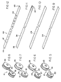
- FIGS. 20-32 depict several of the many possible additional embodiments of the perforated spring 44, FIGS. 8 and 12.
- spring 44A comprises an array of elongated slots of generally uniform size positioned along the longitudinal center axis of the spring.
- the spring 44B of FIG. 21 comprises a similar array of uniform elongated slots, flanked by a line of alternating holes along each outside edges of the spring, with the holes in each line being spaced one hole per two slots.
- the spring 44C of FIG. 22 has a similar array of uniform elongated slots, flanked by two lines of holes along the outside edges of the spring, with a hole at each end of the individual slots.
- FIG. 23 depicts a spring 44D comprising an array of elongated slots of increasing length positioned along the longitudinal center axis of the spring.
- spring 44E comprises an array of generally circular holes of the same size positioned along the longitudinal center axis of the spring.
- the spring 44F of FIG. 25 comprises an array of generally circular, like-sized holes positioned along the longitudinal center axis of the spring, flanked by lines of alternating holes along the outside edges of the spring, with the holes in each line spaced one hole per two slots.
- the spring 44G of FIG. 26 comprises an array of generally circular holes of uniform size positioned along the longitudinal center axis of the spring, flanked by a line of alternating holes along each outside edge of the spring, with the holes in each line being spaced one hole per slot.
- spring 44H comprises five longitudinal lines of generally circular holes of like size, with the holes of adjacent lines positioned at alternating positions along the spring.
- FIG. 28 depicts a spring 44I comprising an array of generally circular holes of increasing radii positioned along the longitudinal center axis of the spring.
- one end of the spring does not have slots, so that the spring torque or force maintains a relatively constant maximum along the slot-free end.
- FIGS. 29 and 30 depict a perforated spring 44K illustratively comprising three sections 112, 113 and 114 which are joined by a tongue-in-groove arrangement 116 (sections 112 and 113) and rivet 117 (sections 113 and 114).
- the spring torque is controlled by the different cross-sectional dimensions of the sections as well as the size and spacing of the perforations.
- FIGS. 31 and 32 depict an alternative, non-perforated sectioned spring 44L, illustratively comprising three sections 118, 119 and 121 which are joined by rivets 122 (sections 118 and 119) and a link 123 (sections 119 and 121).
- the spring torque is controlled by the cross-sectional dimensions of the sections.
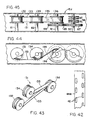
- FIG. 42 depicts yet another alternative perforated spring 44M which, illustratively, comprises two laterally spaced parallel rows of longitudinally spaced, longitudinally elongated slots 42.
- the length of the slots and the spacing between the slots are selected to vary the torque output of the spring along the length of the spring. Slots are preferred to holes because the elongation of the slots has a more uniform cross-section along the width of the spring than circular holes and thus more uniform torque along the length of the slots.
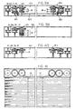
- FIGS. 33-37 illustrate the use of magnetic and detent brakes in spring drives.
- FIG. 33 depicts a spring drive which incorporates two brake devices, a magnet brake 100 and a detent brake 105. Both devices are shown in one figure, although either one or both devices can be used.
- the spring contains thin magnetic or magnetized sections 95 which in the illustrated embodiment extend transverse (side-to-side) on the spring. Preferably, several of the sections are placed closely adjacent one another at locations of the spring where it is desired to stop the spring, for example at spring positions corresponding to blind fully open and fully closed positions and intermediate positions, including a large number of closely spaced intermediate stop positions. For example, FIG.
- FIG. 34 depicts a varied-cove spring embodiment 34A having magnet strip 95-defined stop positions at a multiplicity of positions.
- FIG. 35 depicts an embodiment 34B having magnet strip 95-defined stop positions proximate the ends of the spring.
- FIGS. 36 and 37 illustrate springs 34C and 44J, respectively, having magnet strip 95-defined stop positions at one end of the spring.
- the exemplary magnet brake 100 comprises a magnet bar 101 mounted for pivotal movement by pin or shaft 102 which is mounted to the housing 11.
- Spring 103 is mounted to bar or rod 104 extending from the housing and biases the magnet bar lightly closely adjacent the outside surface of spring such as spring 34A, 34B, 34C and 44J wound on associated drum such as 28.
- the magnet bar 101 rides lightly along or in close proximity to the spring with no effect on the operation of the spring drive until the bar reaches the magnet sections 95, which are attracted to the bar.
- the magnetic force is sufficient to maintain the spring drive and blind at the given position when the blind is brought to rest at that position, and is sufficient to stop a very slowly moving blind at that position (that is, to stop the blind as a person slows movement of the blind to stop it proximate the position of the magnet strips), but is insufficient to stop the blind as it is raised and lowered at a normal speed.
- the detent brake 105 shown in FIG. 33 comprises a bar 106 extending in a transverse direction from the housing 11 adjacent the spring between the associated drums, a detent 107 mounted on a pin 108 projecting downward through a hole in the bar 106, and a spring 109 between the bar 106 and the detent 107 for biasing the detent lightly against the spring.
- the spring 34C may comprise one or a plurality of holes 96 which accept the detent 107.
- holes at selected positions in the perforation-derived varied force spring may be of suitable size to accept the detent.
- the detent 107 has a sloping tip which engages the selected holes with force which is sufficiently great to maintain the spring drive and blind at the given position when the blind is brought to rest at that position, and is sufficiently great to stop a very slowly moving blind at that position (that is, to stop the blind as a person slows movement of the blind to stop it proximate the position of the magnet strips), but is sufficiently small (that is, the detent is sufficiently easy to dislodge from the selected holes) to stop the blind as it is raised and lowered at a normal speed.
- FIGS. 38-41 illustrate examples of the use of spring drive units embodying the present invention in large window covers, for example, heavy covers or wide covers.
- FIG. 38 depicts a single spring drive unit 15G which includes three lift cords and pulleys.
- the illustrated drive unit includes a spring drive such as 26, 31, 41 which is connected by a gear set 65 to the shaft on which the three lift cord pulleys 19 are mounted.
- the associated cords are routed along vertical paths which are spaced along the width of the wide and/or heavy cover, for uniform raising and lowering of the cover.
- FIG. 39 depicts a window cover which includes a pair of drive units 15H, each of which is similar to that of FIG. 38, but includes two pulleys 19 and associated lift cords.
- the spring drives are connected by a power transfer bar unit 125 having bevel gear units 65 on the opposite ends which are connected to the rotating shaft of each spring drive, so that the drives, pulleys, and cords operate precisely in unison.
- the four illustrated pulleys 19 can be used to route four lift cords along vertical paths which are spaced along the width of the cover, for uniformly raising and lowering the wide and/or heavy cover (See FIG. 41).
- FIG. 40 depicts a window cover comprising a pair of spring drive units 15I similar to the units 15G of FIG. 38, but with only one pulley 19 in each unit. This system is used for a two lift cord system, typically for heavy covers.
- FIG. 41 depicts representative examples of the lift cord paths for two and four cord systems.
- FIGS. 43-45 depict a compact spring drive system 15J embodying the present invention and comprising integrally formed plural spring drives.
- the spring drive system comprises plural (two or more) spring drives which share components and are aligned along the width of the associated blind. This integrated alignment provides force multiplication without increasing the size of the associated housing 11 and, specifically, without requiring a taller housing 11.
- the illustrated two spring, spring drive system 131 comprises a first spring drive comprising storage drum or spool 132, common output or power drum or spool 136 and spring 133.
- the second spring drive comprises storage drum or spool 134, common output or power drum or spool 136 and spring 135. As perhaps best shown in FIG.
- the spring 133 is routed from its storage drum 132 beneath the drum 134, from which point the two springs are routed together, with spring 133 under spring 135, over and around common output or power drum 136.
- the two storage spools are mounted for independent rotation so that outer spool 132 can rotate faster than inner spool 134. This is because the diameter of spring 133 on spool 136 is greater than the diameter of spring 135 and thus spring 133 rotates faster on its spool 132 than does spring 135 on its spool 134.
- Different types of springs can be used.
- illustrated spring 135 is a conventional flat spring which provides substantially constant torque, and spring 133 is perforated so that the torque varies along the length of the spring proportional to the operational characteristics of the associated blind, as discussed previously.
- the combined springs provide a combined increased, varying torque sufficient for supporting heavy blinds, yet tailored to the different force requirements as the blind is raised and lowered.
- FIG. 45 depicts one embodiment 15J of a spring drive unit which uses the two spring, spring drive 131.
- the three spools 132, 134 and 136 are mounted on transverse shafts 81, 82, 91, respectively, spaced along the width (horizontally) of the associated housing 11.
- Gear 66 of gear set 65 is mounted on shaft 91 with the output or power spool 136 and meshes with gear 67, which is mounted on shaft 92 along with the cord pulley set 18 comprising right and left side cord pulleys 19, 19.
- the other components such as transmissions 50 and 70 and bevel gear set 60 can be used for transferring power from the spring drive to the cord pulleys and controlling the applied power, the travel of the blind relative to that of the spring drive, and the inherent, braking action.
- three or more springs can be used by the simple expedient of providing additional storage drums or spools and routing their associated springs together over and around the common output or power spool 136.
- a third spring can be added to the drive 131, FIG. 43 and 44 by adding a third storage spool spaced generally horizontally to the left of spool 132, and routing the third spring beneath spring 133.
- the torque is increased by substantially a factor of two simply by adding a second spring the same size as the first spring.
- the increased spring mass required to multiply the torque can be provided by adding additional springs positioned along the horizontal axis of the spring drive, rather than by increasing the spring mass and spool diameter (and thus the height of the spool and the housing), as is the case where a single spring, spring drive is used.
- the storage drums are arranged in a horizontal straight line, or approximately a straight line.
- both the output drum and the storage drums are arranged along the horizontal straight line.
- the storage drums or both the output drum and the storage drums can be positioned along a vertical line.
- the storage drums can be arranged in a cluster, or both the output drum and the storage drums can be arranged in a cluster.
- At least one of the flat springs is adapted for imparting a torque component to the system torque which varies along the length of that spring.
- the said spring has a cove or transverse curvature which selectively varies along the length of the spring for providing the torque which varies proportional to the transverse curvature of that spring at a position closely adjacent the output drum.
- the said spring has at least one hole therein for providing a torque proportional to the transverse size of the hole and the resulting effective width of that spring when the hole is positioned closely adjacent the output drum.
- the said spring has holes along its length for providing a torque which varies proportional to the transverse size of the holes and the resulting effective width of the spring when one or more holes is positioned closely adjacent the output drum.
- cover or blind housing which mounts the blind and the spring drive can be mounted along the bottom of the window or other surface to be covered, so that the blind extends upward for closing and retracts downward for opening.
- top mounted, downward opening blinds and spring drives we describe the operation of top mounted, downward opening blinds and spring drives.
- the invention is applicable to upwardly closing blinds, which typically have a bottom-mounted spring drive unit mount.
- the versatility of the spring drive system according to the present invention in adapting the spring torque characteristics to the operational characteristics of a given cover or blind as well as the braking action of the, make the system applicable to blinds of any operating orientation (top, bottom, lateral, etc.), weight and length.
Landscapes
- Engineering & Computer Science (AREA)
- Structural Engineering (AREA)
- Architecture (AREA)
- Civil Engineering (AREA)
- Blinds (AREA)
- Operating, Guiding And Securing Of Roll- Type Closing Members (AREA)
- Window Of Vehicle (AREA)
- Vehicle Step Arrangements And Article Storage (AREA)
- Dry Shavers And Clippers (AREA)
- Fire-Detection Mechanisms (AREA)
- Piezo-Electric Or Mechanical Vibrators, Or Delay Or Filter Circuits (AREA)
- Specific Sealing Or Ventilating Devices For Doors And Windows (AREA)
Claims (6)
- Fensterabdeckungssystem mit
einer ausziehbaren Fensterabdeckung (12, 22); einem Gehäuse (11); und Tragschnüren (16), die an der Abdeckung befestigt sind und die Rollen (19) umschlingen, die an dem Gehäuse montiert sind, zum Heben und Absenken der ausziehbaren Abdeckung; und
einem Federantriebsystem (15D, 15F), das mit den Tragschnüren verbunden ist, zur Unterstützung des Hebens und Absenkens der Abdeckung, wobei das Federantriebsystem umfasst:eine Band-Transmission (21), die ein Band oder eine Schnur (24) umfasst, welche drehbar um zwei Trommeln geschlungen ist, wobei eine erste der Trommeln funktionsmäßig mit dem drehbaren Ausgabeende des Blattfederantriebs zur Drehung mit diesem verbunden ist und die zweite Trommel funktionsmäßig mit den Tragschnurrollen zur Drehung mit diesen verbunden ist, wobei die Band-Transmission ein Verhältnis hat, das sich verändert, wenn deren Trommeln sich Aufrollen und Abrollen, wobei sie die Rollen mit einer Geschwindigkeit dreht, die sich relativ zu der Geschwindigkeit des drehbaren Ausgabeendes verändert, und das Gesamt-Federantrieb-zu-Rollen-Übersetzungsverhältnis verändert.einen Blattfederantrieb (31, 41), der eine Blattfeder (34, 44) umfasst, die an dem Gehäuse montiert ist und ein Lagerungsende und ein drehbares Ausgabeende hat, wobei das drehbare Ausgabeende ein Drehmoment oder eine Kraft zur Unterstützung des Ausziehens und Zurückziehens der Abdeckung aufbringt; gekennzeichnet durch - Fensterabdeckungssystem nach Anspruch 1, dadurch gekennzeichnet, dass die Band-Transmission funktionsmäßig verbunden ist mit den Rollen durch einen Zahnradsatz mit festem Übersetzungsverhältnis (70, 65), der eine Mehrzahl von ineinandergreifenden Zahnrädern umfasst und einen Eingang und einen Ausgang hat und ein festes Verhältnis zwischen dem Eingang und dem Ausgang, wobei der Ausgang funktionsmäßig mit den Rollen verbunden ist zur Rotation mit diesen und der Eingang funktionsmäßig verbunden ist mit der zweiten Trommel der Band-Transmission zur Rotation mit dieser, um das feste Verhältnis zwischen dem Blattfederantrieb und den Rollen anzuwenden.
- Fensterabdeckungssystem nach Anspruch 1, dadurch gekennzeichnet, dass die Band-Transmission funktionsmäßig mit dem Blattfederantrieb verbunden ist durch einen Zahnradsatz mit festem Verhältnis (65, 70), der eine Mehrzahl von ineinandergreifenden Zahnrädern umfasst und einen Eingang und einen Ausgang hat und ein festes Verhältnis zwischen dem Eingang und dem Ausgang, wobei der Ausgang funktionsmäßig verbunden ist mit der ersten Trommel der Band-Transmission zur Rotation mit dieser und der Eingang funktionsmäßig verbunden ist mit dem drehbaren Ausgabeende des Blattfederantriebs zur Rotation mit diesem, um das feste Verhältnis zwischen dem Blattfederantrieb und den Rollen anzuwenden.
- Fensterabdeckungssystem nach einem der Ansprüche 1 bis 3, wobei die Blattfeder (34, 11, 44) ausgestaltet ist, eine Drehmomentkomponente an das System-Drehmoment weiterzugeben, die entlang der Länge der Blattfeder variiert.
- Fensterabdeckungssystem nach einem der Ansprüche 1 bis 3, wobei die Blattfeder (34) eine Wölbung oder transversale Krümmung (36, 37) hat, die sich selektiv entlang wenigstens eines Abschnitts der Länge der Blattfeder verändert, um ein Drehmoment bereitzustellen, das sich proportional zu der transversalen Krümmung der Blattfeder verändert.
- Fensterabdeckungssystem nach einem der Ansprüche 1 bis 3, wobei die Blattfeder (44) wenigstens ein Loch (47, 48) darin hat, um ein Drehmoment bereitzustellen, das proportional zu der transversalen Abmessung des Lochs und der sich ergebenden effektiven Breite der Blattfeder ist.
Applications Claiming Priority (5)
| Application Number | Priority Date | Filing Date | Title |
|---|---|---|---|
| US96377497A | 1997-11-04 | 1997-11-04 | |
| US963774 | 1997-11-04 | ||
| US98914297A | 1997-12-11 | 1997-12-11 | |
| US989142 | 1997-12-11 | ||
| PCT/US1998/023561 WO1999023343A1 (en) | 1997-11-04 | 1998-11-03 | Flat spring drive system and window cover |
Publications (3)
| Publication Number | Publication Date |
|---|---|
| EP1045954A1 EP1045954A1 (de) | 2000-10-25 |
| EP1045954A4 EP1045954A4 (de) | 2002-11-13 |
| EP1045954B1 true EP1045954B1 (de) | 2005-08-03 |
Family
ID=27130457
Family Applications (1)
| Application Number | Title | Priority Date | Filing Date |
|---|---|---|---|
| EP98956605A Expired - Lifetime EP1045954B1 (de) | 1997-11-04 | 1998-11-03 | Flachfederantrieb und fensterabdeckung |
Country Status (9)
| Country | Link |
|---|---|
| US (2) | US6283192B1 (de) |
| EP (1) | EP1045954B1 (de) |
| JP (1) | JP3688200B2 (de) |
| AT (1) | ATE301235T1 (de) |
| AU (1) | AU753895C (de) |
| BR (1) | BR9815278A (de) |
| CA (1) | CA2308952C (de) |
| DE (1) | DE69831098T2 (de) |
| WO (1) | WO1999023343A1 (de) |
Cited By (1)
| Publication number | Priority date | Publication date | Assignee | Title |
|---|---|---|---|---|
| US9510711B2 (en) | 2012-10-11 | 2016-12-06 | Roman Tsibulevskiy | Partition technologies |
Families Citing this family (98)
| Publication number | Priority date | Publication date | Assignee | Title |
|---|---|---|---|---|
| US6330899B1 (en) | 1994-04-06 | 2001-12-18 | Newell Window Furnishings. Inc. | Cordless balanced window covering |
| US6412537B1 (en) * | 1999-01-12 | 2002-07-02 | Newell Operating Company | Bottom rail weight and balancing system |
| US6648050B1 (en) * | 1997-11-04 | 2003-11-18 | Andrew J. Toti | Spring drive system and window cover |
| US6199664B1 (en) | 1998-11-16 | 2001-03-13 | General Electric Company | Spring motor for generating constant torque |
| US6725897B2 (en) * | 2000-08-22 | 2004-04-27 | Newell Window Furnishings, Inc. | Variable friction device for a cordless blind |
| US6644375B2 (en) | 2001-01-09 | 2003-11-11 | Newell Window Furnishings | Cordless blind brake |
| US7025107B2 (en) * | 2001-07-31 | 2006-04-11 | Newell Window Furnishings, Inc. | One-way tensioning mechanism for cordless blind |
| US6508293B1 (en) * | 2001-09-06 | 2003-01-21 | Tai-Long Huang | Spring motor assembly for a venetian blind without outside hanging lifting cords |
| US6644373B2 (en) * | 2001-11-08 | 2003-11-11 | Newell Window Furnishings, Inc. | Cordless blind |
| US7096917B2 (en) * | 2001-12-14 | 2006-08-29 | Newell Window Furnishings, Inc. | One way brake for a cordless blind |
| US6684930B2 (en) | 2001-12-14 | 2004-02-03 | Newell Window Furnishings, Inc. | Brake for a cordless blind |
| US6675861B2 (en) | 2001-12-14 | 2004-01-13 | Newell Window Furnishings, Inc. | Brake for a cordless blind |
| TW510421U (en) * | 2002-03-07 | 2002-11-11 | Ind Tech Res Inst | Lift cord conceailable venetian blind lift control mechanism |
| AU2003220458A1 (en) * | 2002-03-20 | 2003-10-08 | Rollease Inc. | Semi-cordless unbalanced spring driven blind system and methods for adjusting and making same |
| US6889741B1 (en) * | 2002-06-11 | 2005-05-10 | Zipshade Industrial (B.V.I.) Corp. | Window covering height adjustment apparatus and method using multiple interconnected cord winding rotors |
| US6823925B2 (en) * | 2002-07-12 | 2004-11-30 | Shades Unlimited, Inc. | Retractable window shade with height adjustment control |
| US6880677B2 (en) * | 2002-07-15 | 2005-04-19 | Chuy-Nan Chio | Elastic energy storage device |
| US6962187B2 (en) * | 2002-12-09 | 2005-11-08 | Gilmore Enterprises | Spools for horizontal blinds |
| US20040112548A1 (en) * | 2002-12-12 | 2004-06-17 | Militello David R. | Shade for an arched window |
| TW553307U (en) * | 2003-01-27 | 2003-09-11 | Nien Made Entpr Co Ltd | Power mechanism used in modular window curtains |
| US20080202705A1 (en) * | 2003-02-10 | 2008-08-28 | Zipshade Industrial (B.V.I.) Corp. | Cordless Blinds with Secondary Blind Adjustment Means |
| US8245756B2 (en) * | 2003-02-10 | 2012-08-21 | Li-Ming Cheng | Pull down, push up, shade apparatus |
| US6837294B2 (en) * | 2003-02-10 | 2005-01-04 | Zipshade Industrial (B.V.I.) Corp. | Pull down, push up, shade assembly |
| US20070163727A1 (en) * | 2003-02-10 | 2007-07-19 | Zipshade Industrial (B.V.I.) Corp. | Window Blinds with Gears |
| US7546866B2 (en) * | 2003-03-20 | 2009-06-16 | Springs Window Fashions Lp | Cordless blinds |
| US7143802B2 (en) * | 2003-03-20 | 2006-12-05 | Springs Window Fashions Lp | Cordless blinds |
| US6865817B2 (en) * | 2003-03-27 | 2005-03-15 | Shades Unlimited, Inc. | Window shade with measurement guide |
| US6761203B1 (en) * | 2003-03-31 | 2004-07-13 | Tai-Long Huang | Balanced window blind having a spring motor for concealed pull cords thereof |
| US7093644B2 (en) * | 2003-06-02 | 2006-08-22 | Springs Window Fashions Lp | Window covering with lifting mechanism |
| EP1644273B1 (de) * | 2003-07-16 | 2014-01-15 | Hunter Douglas Inc. | Antrieb für abdeckungen für bauliche öffnungen |
| US7287570B2 (en) * | 2003-10-10 | 2007-10-30 | Springs Window Fashions Lp | Window covering lifting system and method |
| US7331370B1 (en) * | 2004-08-03 | 2008-02-19 | Shades Unlimited, Inc. | Progressive resistance lifting mechanism for a window covering |
| US7168476B2 (en) * | 2004-09-29 | 2007-01-30 | Chin-Fu Chen | Cordless activating device for a venetian blind |
| US7549615B2 (en) * | 2004-10-15 | 2009-06-23 | Shades Unlimited, Inc. | Compression mount for window coverings |
| US8596594B2 (en) * | 2004-10-15 | 2013-12-03 | Shades Unlimited, Inc. | Compression mount for window coverings |
| US7717156B2 (en) * | 2004-12-28 | 2010-05-18 | Barnes Group Inc. | Device for creating an adjustable angular force |
| US20060137830A1 (en) * | 2004-12-29 | 2006-06-29 | Henry Lin | Winding mechanism of blind |
| US20060137831A1 (en) * | 2004-12-29 | 2006-06-29 | Henry Lin | Winding mechanism of blind |
| EP1696098A1 (de) * | 2005-01-26 | 2006-08-30 | Nien Made Enterprise Co., Ltd. | Raffrollo ohne Zugschnur |
| US20060162870A1 (en) * | 2005-01-26 | 2006-07-27 | Nien Made Enterprise Co., Ltd. | Roman blind without any pull rope |
| US7562689B1 (en) | 2005-08-16 | 2009-07-21 | Shades Unlimited, Inc. | Clip for window covering cord |
| CN101336330B (zh) * | 2005-12-12 | 2012-10-31 | 澳大利亚森特股份有限公司 | 横拉卷式纱网组件 |
| US7740045B2 (en) | 2006-10-25 | 2010-06-22 | Hunter Douglas Inc. | Spring motor and drag brake for drive for coverings for architectural openings |
| US8511364B2 (en) * | 2006-01-13 | 2013-08-20 | Hunter Douglas Inc. | Spring motor for drive for coverings for architectural openings |
| TW200742794A (en) * | 2006-05-11 | 2007-11-16 | shi-min Hong | Folding device for cordless blind |
| US20080087386A1 (en) * | 2006-10-16 | 2008-04-17 | Nien Made Enterprise Co., Ltd. | Combination structure of spring power assembly and head rail |
| US8752607B2 (en) | 2007-10-22 | 2014-06-17 | Hunter Douglas Inc. | Covering for architectural openings including a rotation limiter |
| EP1918504A1 (de) * | 2006-10-27 | 2008-05-07 | Nien Made Enterprise Co., Ltd. | Kombination von Federantrieb und länglicher oberer Halterung |
| GB0700706D0 (en) * | 2007-01-13 | 2007-02-21 | Mccormick Gregory R | Controlling a position of a hanging flexible covering |
| US20080185109A1 (en) * | 2007-02-02 | 2008-08-07 | Ker-Min Lin | Reeling device for curtain cords |
| US7703499B2 (en) * | 2007-02-22 | 2010-04-27 | Tait Towers, Inc. | Portable curtain retraction device and system |
| US20080210387A1 (en) * | 2007-03-02 | 2008-09-04 | Chin-Chien Yang | Structure for curtain positioning |
| US20090283223A1 (en) * | 2008-05-15 | 2009-11-19 | Suzhou Hongyi Ornament Material Co. | Cordless window shade |
| US20100206492A1 (en) * | 2009-02-13 | 2010-08-19 | Shades Unlimited, Inc. | Window covering featuring automatic cord collection |
| US8087445B2 (en) * | 2009-06-23 | 2012-01-03 | Newell Window Furnishings, Inc. | Spring motor and window covering |
| US9249623B2 (en) | 2010-02-23 | 2016-02-02 | Qmotion Incorporated | Low-power architectural covering |
| US8659246B2 (en) | 2010-02-23 | 2014-02-25 | Homerun Holdings Corporation | High efficiency roller shade |
| US9194179B2 (en) | 2010-02-23 | 2015-11-24 | Qmotion Incorporated | Motorized shade with the transmission wire passing through the support shaft |
| US8575872B2 (en) | 2010-02-23 | 2013-11-05 | Homerun Holdings Corporation | High efficiency roller shade and method for setting artificial stops |
| US8807196B2 (en) * | 2010-05-04 | 2014-08-19 | Qmotion Incorporated | Modular anti-reversible power spring apparatus and method |
| US8800633B2 (en) | 2010-05-04 | 2014-08-12 | Qmotion Incorporated | Anti-reversible power spring apparatus and method |
| US20120097349A1 (en) * | 2010-10-20 | 2012-04-26 | Chicology, Inc. | Blind |
| US9955825B2 (en) | 2012-10-11 | 2018-05-01 | Roman Tsibulevskiy | Partition technologies |
| US9949597B2 (en) | 2012-10-11 | 2018-04-24 | Roman Tsibulevskiy | Partition technologies |
| US9192267B2 (en) | 2012-10-11 | 2015-11-24 | Roman Tsibulevskiy | Shower curtain technologies |
| US11083344B2 (en) | 2012-10-11 | 2021-08-10 | Roman Tsibulevskiy | Partition technologies |
| US10292538B2 (en) | 2012-10-11 | 2019-05-21 | Roman Tsibulevskiy | Partition technologies |
| US8899298B2 (en) * | 2013-02-05 | 2014-12-02 | Mei-Chin Hsueh Cheng | Window treatment roll-up device |
| US20140262062A1 (en) * | 2013-03-15 | 2014-09-18 | Homerun Holdings Corporation | Method and apparatus for reducing the space requirement of a flat counterbalancing spring with a negative gradient by restraining or containing the free coil of the spring |
| CN104097995B (zh) * | 2013-04-01 | 2016-08-24 | 郑立铭 | 窗帘卷线变速模块 |
| US9103157B2 (en) * | 2013-04-13 | 2015-08-11 | Qmotion Incorporated | Spring counterbalance apparatus and method |
| US9121221B2 (en) | 2013-05-28 | 2015-09-01 | Li-Ming Cheng | Cord-winding assembly of a window blind |
| US9903157B2 (en) | 2013-10-01 | 2018-02-27 | Hunter Douglas Industries B.V. | Rail for an architectural covering |
| US20150129142A1 (en) * | 2013-11-11 | 2015-05-14 | Hua-Chi Huang | Stringless curtain structure |
| JP6326508B2 (ja) | 2014-11-05 | 2018-05-16 | テー ヨー シーオー エルティーディー | 紐なし窓シェード、およびそのばね駆動システム |
| US10221619B2 (en) | 2015-01-21 | 2019-03-05 | Nien Made Enterprise Co., Ltd. | Lifting device of cordless covering |
| US9593530B1 (en) | 2015-08-18 | 2017-03-14 | Hunter Douglas Inc. | Brake assembly for a covering for an architectural opening |
| CN106761338B (zh) * | 2015-11-19 | 2018-11-06 | 郑立铭 | 窗帘卷收变速组件 |
| CN205605050U (zh) * | 2016-01-22 | 2016-09-28 | 亿丰综合工业股份有限公司 | 窗帘的阻尼装置 |
| CN205400553U (zh) * | 2016-03-04 | 2016-07-27 | 关健民 | 一种窗帘 |
| TWM533473U (en) | 2016-03-22 | 2016-12-11 | xian-de Huang | Variable pressure coil spring and spring motor used thereof |
| US9957750B2 (en) | 2016-06-09 | 2018-05-01 | Whole Space Industries Ltd | Window covering positional adjustment apparatus |
| US10415306B2 (en) | 2017-07-05 | 2019-09-17 | Whole Space Industries Ltd | Window covering and stability mechanism for the same |
| US10550635B2 (en) | 2017-08-09 | 2020-02-04 | Whole Space Industries Ltd | Window covering control apparatus |
| CN107485269A (zh) * | 2017-09-18 | 2017-12-19 | 杭州瑞苒科技有限公司 | 窗帘用儿童安全拉线及窗帘 |
| US10676988B2 (en) | 2017-09-20 | 2020-06-09 | Whole Space Industries Ltd. | Window covering control apparatus |
| TWI676733B (zh) * | 2017-09-25 | 2019-11-11 | 德侑股份有限公司 | 窗簾和其彈簧驅動系統 |
| USD865223S1 (en) | 2017-11-03 | 2019-10-29 | Centor Design Pty Ltd | Screen mounting tube |
| JP7236210B2 (ja) * | 2017-11-10 | 2023-03-09 | 立川ブラインド工業株式会社 | 遮蔽装置 |
| CN107989537A (zh) * | 2017-12-22 | 2018-05-04 | 深圳市万氏窗饰有限公司 | 一种柔性变力的帘布收放装置 |
| US11142944B2 (en) | 2017-12-28 | 2021-10-12 | Home Depot Product Authority, Llc | Slat angle adjustment mechanism for window blinds |
| US12460475B2 (en) | 2017-12-28 | 2025-11-04 | Home Depot Product Authority, Llc | Motorized slat angle adjustment mechanism for window blinds |
| KR102565322B1 (ko) * | 2018-07-30 | 2023-08-09 | 엘지전자 주식회사 | 디스플레이 디바이스 |
| US11230881B2 (en) * | 2018-09-26 | 2022-01-25 | Nien Made Enterprise Co., Ltd. | Block and tackle window blind |
| US20200180902A1 (en) * | 2018-12-11 | 2020-06-11 | Supreme Plastic Products Co., Ltd. | Elasticity changeable structure of curtain reeling device |
| US11149489B2 (en) | 2019-03-05 | 2021-10-19 | Hunter Douglas Inc. | Transmission for an architectural-structure covering |
| USD935221S1 (en) | 2019-06-26 | 2021-11-09 | Whole Space Industries Ltd | Bottom rail for a window covering |
| CN111210729B (zh) * | 2020-02-28 | 2022-08-26 | 上海天马微电子有限公司 | 一种可折叠显示装置 |
Family Cites Families (31)
| Publication number | Priority date | Publication date | Assignee | Title |
|---|---|---|---|---|
| US13251A (en) | 1855-07-17 | Window-blind | ||
| US2087354A (en) * | 1936-04-14 | 1937-07-20 | Gulf Research Development Co | Spring |
| US2266160A (en) | 1940-12-26 | 1941-12-16 | Columbia Mills Inc | Spring actuated blind |
| US2276716A (en) | 1941-03-17 | 1942-03-17 | Carlos J Cardona | Venetian blind |
| FR883709A (fr) | 1941-07-05 | 1943-07-13 | Alb Fritz Ebert | Store plissé à relevage automatique |
| US2324536A (en) | 1942-01-19 | 1943-07-20 | Transp Equipment Co | Closure structure |
| US2390826A (en) | 1943-12-16 | 1945-12-11 | Automatic Venetian Hardware Co | Cordless venetian blind |
| US2420301A (en) | 1944-11-20 | 1947-05-13 | Cusumano Rudolph | Venetian blind |
| US2824608A (en) | 1955-09-27 | 1958-02-25 | Chamberlain Corp | Venetian blind |
| US3139877A (en) | 1961-02-21 | 1964-07-07 | Graybill Ind Inc | Mechanical starter motor energized by engine operation |
| US3151704A (en) | 1962-05-21 | 1964-10-06 | Ametek Inc | Spring motor |
| AT260995B (de) * | 1964-01-22 | 1968-04-10 | Willy Buehler Ag | Schleppvorrichtung |
| US3194343A (en) * | 1964-05-04 | 1965-07-13 | Ametek Inc | Spring motor |
| US3363891A (en) * | 1966-04-11 | 1968-01-16 | Edwin E. Foster | Compound curved spring motor |
| US3756585A (en) | 1971-09-09 | 1973-09-04 | A Mihalcheon | Spiral spring counterbalance unit |
| US4399959A (en) | 1981-10-26 | 1983-08-23 | International Business Machines Corp. | Constant force windup spring web threading system |
| SU1068583A1 (ru) | 1982-08-24 | 1984-01-23 | Марийское специальное конструкторско-технологическое бюро торгового холодильного оборудования | Устройство дл свертывани шторы |
| US4472910A (en) | 1982-09-29 | 1984-09-25 | Chamnberlain Manufacturing Corporation | Integral device for garage door opener |
| US4784122A (en) | 1984-03-01 | 1988-11-15 | Graham Erwin W | Portable cervical traction device using constant force springs |
| US4635755A (en) | 1985-01-16 | 1987-01-13 | Ametek, Inc. | Backwound pre-stressed spring motor and method |
| US4664531A (en) | 1985-11-13 | 1987-05-12 | V. E. Kuster Company, Inc. | Downhole clock spring |
| US5105867A (en) | 1990-05-07 | 1992-04-21 | Coslett Fred L | Collapsible sun shade and improved method for shielding the sun |
| US5170830A (en) | 1990-05-07 | 1992-12-15 | Coslett Fred L | Sun shade |
| US5054162A (en) | 1990-08-17 | 1991-10-08 | Schlegel Corporation | Constant force compensation for power spring weight balance |
| US5133399A (en) | 1990-12-17 | 1992-07-28 | Hiller Jeffrey H | Apparatus by which horizontal and vertical blinds, pleated shades, drapes and the like may be balanced for "no load" operation |
| US5157808A (en) * | 1992-02-18 | 1992-10-27 | Product Design & Development, Inc. | Coil spring counterbalance hardware assembly and connection method therefor |
| US5482100A (en) * | 1994-04-06 | 1996-01-09 | Newell Operating Company | Cordless, balanced venetian blind or shade with consistent variable force spring motor |
| US5531257A (en) | 1994-04-06 | 1996-07-02 | Newell Operating Company | Cordless, balanced window covering |
| JP3414864B2 (ja) | 1994-10-26 | 2003-06-09 | 三菱電機株式会社 | 幕状体巻取り装置 |
| US6149094A (en) | 1996-03-20 | 2000-11-21 | Barnes Group Inc. | Spring motor |
| US5813447A (en) | 1996-07-29 | 1998-09-29 | Lysyj; Phillip A. | Cordless cellular and pleated shade |
-
1998
- 1998-11-03 CA CA002308952A patent/CA2308952C/en not_active Expired - Lifetime
- 1998-11-03 BR BR9815278-5A patent/BR9815278A/pt active IP Right Grant
- 1998-11-03 WO PCT/US1998/023561 patent/WO1999023343A1/en not_active Ceased
- 1998-11-03 AT AT98956605T patent/ATE301235T1/de not_active IP Right Cessation
- 1998-11-03 AU AU13091/99A patent/AU753895C/en not_active Expired
- 1998-11-03 EP EP98956605A patent/EP1045954B1/de not_active Expired - Lifetime
- 1998-11-03 JP JP2000519183A patent/JP3688200B2/ja not_active Expired - Lifetime
- 1998-11-03 DE DE69831098T patent/DE69831098T2/de not_active Expired - Lifetime
-
1999
- 1999-01-13 US US09/229,595 patent/US6283192B1/en not_active Expired - Lifetime
-
2001
- 2001-02-12 US US09/782,013 patent/US20020033240A1/en not_active Abandoned
Cited By (1)
| Publication number | Priority date | Publication date | Assignee | Title |
|---|---|---|---|---|
| US9510711B2 (en) | 2012-10-11 | 2016-12-06 | Roman Tsibulevskiy | Partition technologies |
Also Published As
| Publication number | Publication date |
|---|---|
| US6283192B1 (en) | 2001-09-04 |
| JP2001522011A (ja) | 2001-11-13 |
| DE69831098T2 (de) | 2006-06-08 |
| CA2308952A1 (en) | 1999-05-14 |
| CA2308952C (en) | 2004-11-09 |
| AU753895C (en) | 2003-08-21 |
| DE69831098D1 (de) | 2005-09-08 |
| JP3688200B2 (ja) | 2005-08-24 |
| ATE301235T1 (de) | 2005-08-15 |
| AU753895B2 (en) | 2002-10-31 |
| AU1309199A (en) | 1999-05-24 |
| BR9815278A (pt) | 2001-11-27 |
| WO1999023343A1 (en) | 1999-05-14 |
| US20020033240A1 (en) | 2002-03-21 |
| EP1045954A4 (de) | 2002-11-13 |
| EP1045954A1 (de) | 2000-10-25 |
Similar Documents
| Publication | Publication Date | Title |
|---|---|---|
| EP1045954B1 (de) | Flachfederantrieb und fensterabdeckung | |
| US9316051B2 (en) | Window cover system with spring drive arrangement | |
| EP1671008B1 (de) | Umkehrbarer zugschnurmechanismus und system | |
| EP1690022B1 (de) | Manuelles Betätigungselement mit Freilauffunktion für einen Spiralstangenantrieb | |
| US5799715A (en) | Liftable window covering with multiple lifting cords and a single pull cord | |
| US6293329B1 (en) | Coil spring drive system and window cover | |
| AU2003200330B2 (en) | Flat spring drive system and window cover |
Legal Events
| Date | Code | Title | Description |
|---|---|---|---|
| PUAI | Public reference made under article 153(3) epc to a published international application that has entered the european phase |
Free format text: ORIGINAL CODE: 0009012 |
|
| 17P | Request for examination filed |
Effective date: 20000526 |
|
| AK | Designated contracting states |
Kind code of ref document: A1 Designated state(s): AT BE CH CY DE DK ES FI FR GB GR IE IT LI LU MC NL PT SE |
|
| A4 | Supplementary search report drawn up and despatched |
Effective date: 20020926 |
|
| AK | Designated contracting states |
Kind code of ref document: A4 Designated state(s): AT BE CH CY DE DK ES FI FR GB GR IE IT LI LU MC NL PT SE |
|
| RIC1 | Information provided on ipc code assigned before grant |
Free format text: 7E 06B 9/30 A, 7E 06B 9/60 B, 7E 06B 9/62 B |
|
| 17Q | First examination report despatched |
Effective date: 20030530 |
|
| GRAP | Despatch of communication of intention to grant a patent |
Free format text: ORIGINAL CODE: EPIDOSNIGR1 |
|
| GRAS | Grant fee paid |
Free format text: ORIGINAL CODE: EPIDOSNIGR3 |
|
| GRAA | (expected) grant |
Free format text: ORIGINAL CODE: 0009210 |
|
| AK | Designated contracting states |
Kind code of ref document: B1 Designated state(s): AT BE CH CY DE DK ES FI FR GB GR IE IT LI LU MC NL PT SE |
|
| PG25 | Lapsed in a contracting state [announced via postgrant information from national office to epo] |
Ref country code: NL Free format text: LAPSE BECAUSE OF FAILURE TO SUBMIT A TRANSLATION OF THE DESCRIPTION OR TO PAY THE FEE WITHIN THE PRESCRIBED TIME-LIMIT Effective date: 20050803 Ref country code: LI Free format text: LAPSE BECAUSE OF FAILURE TO SUBMIT A TRANSLATION OF THE DESCRIPTION OR TO PAY THE FEE WITHIN THE PRESCRIBED TIME-LIMIT Effective date: 20050803 Ref country code: IT Free format text: LAPSE BECAUSE OF FAILURE TO SUBMIT A TRANSLATION OF THE DESCRIPTION OR TO PAY THE FEE WITHIN THE PRESCRIBED TIME-LIMIT;WARNING: LAPSES OF ITALIAN PATENTS WITH EFFECTIVE DATE BEFORE 2007 MAY HAVE OCCURRED AT ANY TIME BEFORE 2007. THE CORRECT EFFECTIVE DATE MAY BE DIFFERENT FROM THE ONE RECORDED. Effective date: 20050803 Ref country code: FI Free format text: LAPSE BECAUSE OF FAILURE TO SUBMIT A TRANSLATION OF THE DESCRIPTION OR TO PAY THE FEE WITHIN THE PRESCRIBED TIME-LIMIT Effective date: 20050803 Ref country code: CH Free format text: LAPSE BECAUSE OF FAILURE TO SUBMIT A TRANSLATION OF THE DESCRIPTION OR TO PAY THE FEE WITHIN THE PRESCRIBED TIME-LIMIT Effective date: 20050803 Ref country code: BE Free format text: LAPSE BECAUSE OF FAILURE TO SUBMIT A TRANSLATION OF THE DESCRIPTION OR TO PAY THE FEE WITHIN THE PRESCRIBED TIME-LIMIT Effective date: 20050803 Ref country code: AT Free format text: LAPSE BECAUSE OF FAILURE TO SUBMIT A TRANSLATION OF THE DESCRIPTION OR TO PAY THE FEE WITHIN THE PRESCRIBED TIME-LIMIT Effective date: 20050803 |
|
| REG | Reference to a national code |
Ref country code: GB Ref legal event code: FG4D |
|
| REG | Reference to a national code |
Ref country code: CH Ref legal event code: EP |
|
| REG | Reference to a national code |
Ref country code: IE Ref legal event code: FG4D |
|
| REF | Corresponds to: |
Ref document number: 69831098 Country of ref document: DE Date of ref document: 20050908 Kind code of ref document: P |
|
| PG25 | Lapsed in a contracting state [announced via postgrant information from national office to epo] |
Ref country code: SE Free format text: LAPSE BECAUSE OF FAILURE TO SUBMIT A TRANSLATION OF THE DESCRIPTION OR TO PAY THE FEE WITHIN THE PRESCRIBED TIME-LIMIT Effective date: 20051103 Ref country code: IE Free format text: LAPSE BECAUSE OF NON-PAYMENT OF DUE FEES Effective date: 20051103 Ref country code: GR Free format text: LAPSE BECAUSE OF FAILURE TO SUBMIT A TRANSLATION OF THE DESCRIPTION OR TO PAY THE FEE WITHIN THE PRESCRIBED TIME-LIMIT Effective date: 20051103 Ref country code: DK Free format text: LAPSE BECAUSE OF FAILURE TO SUBMIT A TRANSLATION OF THE DESCRIPTION OR TO PAY THE FEE WITHIN THE PRESCRIBED TIME-LIMIT Effective date: 20051103 Ref country code: CY Free format text: LAPSE BECAUSE OF FAILURE TO SUBMIT A TRANSLATION OF THE DESCRIPTION OR TO PAY THE FEE WITHIN THE PRESCRIBED TIME-LIMIT Effective date: 20051103 |
|
| PG25 | Lapsed in a contracting state [announced via postgrant information from national office to epo] |
Ref country code: ES Free format text: LAPSE BECAUSE OF FAILURE TO SUBMIT A TRANSLATION OF THE DESCRIPTION OR TO PAY THE FEE WITHIN THE PRESCRIBED TIME-LIMIT Effective date: 20051114 |
|
| PG25 | Lapsed in a contracting state [announced via postgrant information from national office to epo] |
Ref country code: MC Free format text: LAPSE BECAUSE OF NON-PAYMENT OF DUE FEES Effective date: 20051130 Ref country code: LU Free format text: LAPSE BECAUSE OF NON-PAYMENT OF DUE FEES Effective date: 20051130 |
|
| REG | Reference to a national code |
Ref country code: GB Ref legal event code: 727 |
|
| PG25 | Lapsed in a contracting state [announced via postgrant information from national office to epo] |
Ref country code: PT Free format text: LAPSE BECAUSE OF FAILURE TO SUBMIT A TRANSLATION OF THE DESCRIPTION OR TO PAY THE FEE WITHIN THE PRESCRIBED TIME-LIMIT Effective date: 20060103 |
|
| NLV1 | Nl: lapsed or annulled due to failure to fulfill the requirements of art. 29p and 29m of the patents act | ||
| REG | Reference to a national code |
Ref country code: CH Ref legal event code: PL |
|
| PLBE | No opposition filed within time limit |
Free format text: ORIGINAL CODE: 0009261 |
|
| STAA | Information on the status of an ep patent application or granted ep patent |
Free format text: STATUS: NO OPPOSITION FILED WITHIN TIME LIMIT |
|
| REG | Reference to a national code |
Ref country code: GB Ref legal event code: 727 |
|
| 26N | No opposition filed |
Effective date: 20060504 |
|
| REG | Reference to a national code |
Ref country code: IE Ref legal event code: MM4A |
|
| REG | Reference to a national code |
Ref country code: GB Ref legal event code: 727A |
|
| EN | Fr: translation not filed | ||
| PG25 | Lapsed in a contracting state [announced via postgrant information from national office to epo] |
Ref country code: FR Free format text: LAPSE BECAUSE OF FAILURE TO SUBMIT A TRANSLATION OF THE DESCRIPTION OR TO PAY THE FEE WITHIN THE PRESCRIBED TIME-LIMIT Effective date: 20060929 |
|
| REG | Reference to a national code |
Ref country code: GB Ref legal event code: 727B |
|
| PG25 | Lapsed in a contracting state [announced via postgrant information from national office to epo] |
Ref country code: FR Free format text: LAPSE BECAUSE OF FAILURE TO SUBMIT A TRANSLATION OF THE DESCRIPTION OR TO PAY THE FEE WITHIN THE PRESCRIBED TIME-LIMIT Effective date: 20051130 |
|
| PG25 | Lapsed in a contracting state [announced via postgrant information from national office to epo] |
Ref country code: FR Free format text: LAPSE BECAUSE OF FAILURE TO SUBMIT A TRANSLATION OF THE DESCRIPTION OR TO PAY THE FEE WITHIN THE PRESCRIBED TIME-LIMIT Effective date: 20050803 |
|
| PGFP | Annual fee paid to national office [announced via postgrant information from national office to epo] |
Ref country code: DE Payment date: 20171102 Year of fee payment: 20 |
|
| PGFP | Annual fee paid to national office [announced via postgrant information from national office to epo] |
Ref country code: GB Payment date: 20171026 Year of fee payment: 20 |
|
| REG | Reference to a national code |
Ref country code: DE Ref legal event code: R071 Ref document number: 69831098 Country of ref document: DE |
|
| REG | Reference to a national code |
Ref country code: GB Ref legal event code: PE20 Expiry date: 20181102 |
|
| PG25 | Lapsed in a contracting state [announced via postgrant information from national office to epo] |
Ref country code: GB Free format text: LAPSE BECAUSE OF EXPIRATION OF PROTECTION Effective date: 20181102 |