EP1045958B1 - Tube de forage et procede de fa onnage et de reconditionnement d'un tube de forage - Google Patents
Tube de forage et procede de fa onnage et de reconditionnement d'un tube de forage Download PDFInfo
- Publication number
- EP1045958B1 EP1045958B1 EP99901246A EP99901246A EP1045958B1 EP 1045958 B1 EP1045958 B1 EP 1045958B1 EP 99901246 A EP99901246 A EP 99901246A EP 99901246 A EP99901246 A EP 99901246A EP 1045958 B1 EP1045958 B1 EP 1045958B1
- Authority
- EP
- European Patent Office
- Prior art keywords
- drill pipe
- journal
- tool
- hardfacing material
- length
- Prior art date
- Legal status (The legal status is an assumption and is not a legal conclusion. Google has not performed a legal analysis and makes no representation as to the accuracy of the status listed.)
- Expired - Lifetime
Links
- 238000000034 method Methods 0.000 title claims description 44
- 238000005552 hardfacing Methods 0.000 claims description 36
- 239000000463 material Substances 0.000 claims description 35
- 230000008878 coupling Effects 0.000 claims description 16
- 238000010168 coupling process Methods 0.000 claims description 16
- 238000005859 coupling reaction Methods 0.000 claims description 16
- 238000005553 drilling Methods 0.000 claims description 13
- 239000007921 spray Substances 0.000 claims description 6
- 238000002485 combustion reaction Methods 0.000 claims description 5
- 238000001816 cooling Methods 0.000 claims description 5
- 239000000446 fuel Substances 0.000 claims description 5
- 238000005461 lubrication Methods 0.000 claims description 5
- 238000005507 spraying Methods 0.000 claims description 5
- 238000004519 manufacturing process Methods 0.000 claims description 4
- 229910003460 diamond Inorganic materials 0.000 claims description 3
- 239000010432 diamond Substances 0.000 claims description 3
- 238000005121 nitriding Methods 0.000 claims description 3
- 229910010293 ceramic material Inorganic materials 0.000 claims description 2
- 239000000843 powder Substances 0.000 claims description 2
- PNEYBMLMFCGWSK-UHFFFAOYSA-N Alumina Chemical compound [O-2].[O-2].[O-2].[Al+3].[Al+3] PNEYBMLMFCGWSK-UHFFFAOYSA-N 0.000 description 3
- 238000003754 machining Methods 0.000 description 3
- 239000012530 fluid Substances 0.000 description 2
- 238000005242 forging Methods 0.000 description 2
- 238000013459 approach Methods 0.000 description 1
- 239000000919 ceramic Substances 0.000 description 1
- 230000001010 compromised effect Effects 0.000 description 1
- 238000010276 construction Methods 0.000 description 1
- 238000007796 conventional method Methods 0.000 description 1
- 238000005520 cutting process Methods 0.000 description 1
- 230000003247 decreasing effect Effects 0.000 description 1
- 239000000314 lubricant Substances 0.000 description 1
- 238000012986 modification Methods 0.000 description 1
- 230000004048 modification Effects 0.000 description 1
- 230000009467 reduction Effects 0.000 description 1
- 238000010561 standard procedure Methods 0.000 description 1
- 238000012546 transfer Methods 0.000 description 1
- 230000007704 transition Effects 0.000 description 1
- 239000002023 wood Substances 0.000 description 1
Images


Classifications
-
- E—FIXED CONSTRUCTIONS
- E21—EARTH OR ROCK DRILLING; MINING
- E21B—EARTH OR ROCK DRILLING; OBTAINING OIL, GAS, WATER, SOLUBLE OR MELTABLE MATERIALS OR A SLURRY OF MINERALS FROM WELLS
- E21B17/00—Drilling rods or pipes; Flexible drill strings; Kellies; Drill collars; Sucker rods; Cables; Casings; Tubings
- E21B17/10—Wear protectors; Centralising devices, e.g. stabilisers
-
- E—FIXED CONSTRUCTIONS
- E21—EARTH OR ROCK DRILLING; MINING
- E21B—EARTH OR ROCK DRILLING; OBTAINING OIL, GAS, WATER, SOLUBLE OR MELTABLE MATERIALS OR A SLURRY OF MINERALS FROM WELLS
- E21B17/00—Drilling rods or pipes; Flexible drill strings; Kellies; Drill collars; Sucker rods; Cables; Casings; Tubings
- E21B17/10—Wear protectors; Centralising devices, e.g. stabilisers
- E21B17/1057—Centralising devices with rollers or with a relatively rotating sleeve
- E21B17/1064—Pipes or rods with a relatively rotating sleeve
-
- E—FIXED CONSTRUCTIONS
- E21—EARTH OR ROCK DRILLING; MINING
- E21B—EARTH OR ROCK DRILLING; OBTAINING OIL, GAS, WATER, SOLUBLE OR MELTABLE MATERIALS OR A SLURRY OF MINERALS FROM WELLS
- E21B19/00—Handling rods, casings, tubes or the like outside the borehole, e.g. in the derrick; Apparatus for feeding the rods or cables
- E21B19/14—Racks, ramps, troughs or bins, for holding the lengths of rod singly or connected; Handling between storage place and borehole
- E21B19/15—Racking of rods in horizontal position; Handling between horizontal and vertical position
-
- E—FIXED CONSTRUCTIONS
- E21—EARTH OR ROCK DRILLING; MINING
- E21B—EARTH OR ROCK DRILLING; OBTAINING OIL, GAS, WATER, SOLUBLE OR MELTABLE MATERIALS OR A SLURRY OF MINERALS FROM WELLS
- E21B29/00—Cutting or destroying pipes, packers, plugs or wire lines, located in boreholes or wells, e.g. cutting of damaged pipes, of windows; Deforming of pipes in boreholes or wells; Reconditioning of well casings while in the ground
- E21B29/10—Reconditioning of well casings, e.g. straightening
Definitions
- the present invention relates to a drill pipe, a method of forming drill pipe and drill pipe formed thereby as well as to a method of reconditioning drill pipe formed by conventional methods.
- WO 95/05521 discloses a drill string torque-reducing sub-assembly comprising a hollow longitudinally-extending mandrel capable of being coupled between adjacent drill pipes in a drill string; and a sleeve capable of freely rotating about the mandrel.
- US 2,318,263 discloses a method of securing a hard material in position upon a tool joint.
- the object of the present invention is to provide a drill pipe having an integrally formed journal area having improved hardness, roundness and smoothness and methods of forming a journal on a drill pipe, or to at least provide the public with a useful choice.
- a drill pipe having coupling sections at either end thereof; a pair of stop collars integrally formed with the drill pipe and extending radially outward; and a hardfacing material applied to the outer surface of the drill pipe between the stop collars to form a journal for supporting a rotating tool; characterised in that the stop collars are positioned so that for a tool of a given length, the journal is greater than the tool length by an amount sufficient to allow the rotating tool to move along the journal and promote lubrication and cooling of the interface between the tool and the drill pipe.
- a journal on a drill pipe manufacture comprising:
- the hardfacing is preferably an amorphous type hardfacing.
- the hardfacing may be applied by high velocity oxy fuel, plasma spray, combustion wire, arc wire spraying, flame thermal spray, nitriding carburising or other case hardening techniques.
- the hardfacing may be a ceramic material or PDC (polycrystalline diamond compact).
- the hardfacing material is preferably applied by spluttering, for example by twin arc or high velocity oxy fuel spraying the hardfacing material directly onto the existing drill pipe.
- the hardfacing material is preferably ARMORCOR M or ARNCO with options being Rolls Wood or other suitable materials.
- a drill pipe having coupling sections at either end thereof and a journal formed on the drill pipe between said coupling sections, the ovality of the journal being less than or equal to 0.7mm.
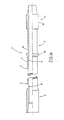
- a drill pipe 1 having an integrally formed journal generally indicated by the numeral 2.
- the drill string has a female coupling section 3 at one end, a male coupling section 4 at the other end and a pipe section 5 therebetween.
- Female coupling 3 and male coupling 4 are preferably formed by forging and are friction welded to respective ends of pipe section 5 at areas 6 and 7.
- the thickness of the drill pipe is seen to vary gradually from female coupling 3 and male coupling 4 to pipe section 5 at points 8 and 9. This gradual tapering avoids the creation of a stress point at a rapid transition.
- Integrally formed collars 10 and 11 define a journal surface 12 therebetween.
- the pipe string is formed substantially in accordance with standard procedures apart from the procedures for forming journal 2.
- Female portion 3 and male portion 4 (including journal 2) are formed by forging and are friction welded to pipe section 5.
- Male fitting 4 is forged in a shape including collars 10 and 11 and journal surface 12.
- journal surface 12 Prior to heat treating the drill pipe in a standard forming procedure an amorphous type hardfacing material is applied to journal surface 12.
- the hardfacing surface may be formed on journal surface 12 using case hardening techniques, such as nitriding or carburising.
- case hardening techniques such as nitriding or carburising.
- high velocity oxy fuel, plasma spray, combustion powder, combustion wire, arc wire spraying, or flame thermal spray techniques may be used.
- a ceramic layer or a PDC (polycrystalline diamond compact) layer may be applied.
- journal surface 12 of the drill pipe so formed is then precision ground to form a smooth round journal surface upon which a tool may be fitted.
- collars 10 and 1 are integrally formed during manufacture of the drill pipe 1 no additional collars need to be provided. Due to the smoothness of journal 12 the problems associated with fitting tools directly to drill pipes encountered in the prior art may be substantially overcome.
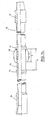
- FIG. 1b there is shown a drill pipe 19 having male and female coupling sections 13 and 14 at either end thereof.
- Journal 15 is located at a central region of the drill pipe 1 9 and stop collars 1 6 and 1 7 are integrally formed with drill pipe 19 at either end of journal 15.
- a rotatable drilling tool 18 is secured about journal 15.
- a rotatable drilling tool 18 may be a multi-part drilling tool as described in WO 96/34173 , or similar, which is able to be secured about journal 15 in use.
- the length b of journal 15 is preferably sufficiently greater than the length a of rotatable drilling tool 18 to allow effective lubrication and cooling of the interface between journal 15 and rotatable drilling tool 18.
- Length b is preferably at least 20% greater than length a, preferably length b is more than 35% greater than length a, more preferably length b is more than 50% greater than length a.
- collars 16 and 17 are provided at a central location along drill pipe 19.
- the stop collar 10 and stop collar formed by male coupling section 11 were provided at one end of the drill pipe 1.
- FIG. 1c there is shown a drill pipe 25 having male and female coupling sections 26 and 27 at either end thereof.
- Journal 28 is formed on drill pipe 25 and a rotatable tool 29 is mounted upon journal 28.
- moveable stop collars 30 and 31 are secured at either end of journal 28.
- Stop collars 30 and 31 may be of two part construction so that they can be secured to drill pipe 25 in use. This arrangement allows the spacing between the stop collars to be varied depending upon the tool secured to the drill pipe. It also simplifies the manufacture of drill pipe as the stop collars do not need to be integrally formed, particularly for central areas of the drill pipe. This approach is also applicable where a journal is to be formed upon an existing section of drill string.
- the journals of the drill pipes described in figures 1 a to 1 c should be round, hard and smooth to minimise wear of the journal surface and rotatable tool.
- the surface of the tool should have a roughness of less than 0.8 micrometres.
- the journal should have an ovality of less than or equal to 0.7 mm, preferably less than 0.5 mm and more preferably less than 0.25 mm.
- the journal should also have a surface hardness of greater than or equal to 35 Rc, preferably greater than 38 Rc.
- the length of the journal will typically be less than 3 metres.
- a drill pipe 20 is shown prior to reconditioning.
- a section 21 of the drill pipe is lightly machined, preferably by rotating the drill pipe in a lathe relative to bit 22 which moves along the section 21.
- the extent of machining has been greatly exaggerated for illustrative purposes.
- a hardfacing material is applied.
- the procedure used to form the hardfacing must not heat the drill pipe 20 in such a manner as to affect its temper.
- One method is to apply material by spluttering, preferably by twin arc or high velocity oxy fuel spraying hardfacing material 23 directly onto section 21 of the drill pipe. This technique requires careful preheating of the drill pipe to a temperature which is not so hot as to affect the temper of the pipe but not so cold that the hardfacing will not be successfully applied.
- the hardfacing material 23 is deposited using a finely calibrated arc transfer pressure.
- a back-step application technique may be required to ensure that the base material temperature remains within acceptable limits.
- Preferred hardfacing materials are ARMORCOR M or ARNCO. It will, however, be appreciated that other suitable techniques or materials may be employed as long as the above requirements are met.
- journal surface 21 is round and smooth.
- a drilling tool may then be installed onto the drill pipe in the normal way. If required, collars may be provided at either end of journal section 21.
- the invention thus provides an improved drill pipe including an integrally formed journal which enables rotatable tools to be directly mounted to the journal surface resulting in decreased friction between the tool and the drill pipe and minimising wear on the drill pipe.
Landscapes
- Engineering & Computer Science (AREA)
- Geology (AREA)
- Life Sciences & Earth Sciences (AREA)
- Mining & Mineral Resources (AREA)
- Physics & Mathematics (AREA)
- Environmental & Geological Engineering (AREA)
- Fluid Mechanics (AREA)
- General Life Sciences & Earth Sciences (AREA)
- Geochemistry & Mineralogy (AREA)
- Mechanical Engineering (AREA)
- Drilling Tools (AREA)
- Earth Drilling (AREA)
- Processing Of Stones Or Stones Resemblance Materials (AREA)
- Perforating, Stamping-Out Or Severing By Means Other Than Cutting (AREA)
Claims (32)
- Tube de forage, comportant:des sections d'accouplement (3, 4) au niveau de chaque extrémité;une paire de colliers de butée (10, 11), formés d'une seule pièce avec le tube de forage et s'étendant radialement vers l'extérieur; etun matériau de rechargement dur appliqué sur la surface externe du tube de forage entre les colliers de butée (10, 11) pour former un tourillon (12) pour supporter un outil rotatif;caractérisé en ce que les colliers de butée (10, 11) sont positionnés de sorte que pour un outil ayant une longueur définie, le tourillon (12) dépasse la longueur de l'outil d'une distance suffisante pour permettre le déplacement de l'outil rotatif le long du tourillon (12) et pour activer la lubrification et le refroidissement de l'interface entre l'outil et le tube de forage.
- Tube de forage selon la revendication 1, dans lequel un collier de butée (10, 11) constitue l'une des sections d'accouplement (3, 4).
- Tube de forage selon les revendications 1 ou 2, dans lequel le tourillon (12) est agencé dans une région centrale du tube de forage, entre les sections d'accouplement.
- Tube de forage selon l'une quelconque des revendications précédentes, dans lequel la surface du tourillon (12) présente une rugosité inférieure à 0,8 micromètres.
- Tube de forage selon l'une quelconque des revendications précédentes, dans lequel l'ovalisation du tourillon (12) est inférieure ou égale à 0,7 mm, de préférence inférieure à 0,5 mm, dans les cas plus préférés inférieure à 0,25 mm.
- Tube de forage selon l'une quelconque des revendications précédentes, dans lequel la longueur effective du tourillon (12) est inférieure à 3 mètres.
- Tube de forage selon l'une quelconque des revendications précédentes, dans lequel le tourillon (12) a une dureté de surface supérieure ou égale à 35 Rc, de préférence supérieure à 38 Rc.
- Tube de forage selon l'une quelconque des revendications précédentes, dans lequel l'espacement entre les colliers de butée (10, 11) est supérieur d'au moins 20%, de préférence de 35%, à la longueur de l'outil.
- Tube de forage selon les revendications 1 à 7, dans lequel l'espacement des colliers de butée (10, 11) est supérieur d'au moins 50% à la longueur de l'outil.
- Combinaison comprenant un tube de forage (5) selon l'une quelconque des revendications précédentes, et un outil de forage (18), l'outil pouvant être fixé autour du tourillon (12) du tube de forage, de sorte que le tourillon (12) est au moins partiellement agencé dans un alésage dans l'outil de forage.
- Combinaison selon la revendication 10, dans laquelle l'espacement entre les colliers de butée (10, 11) est supérieur d'au moins 20% à la longueur de l'outil.
- Combinaison selon la revendication 10, dans laquelle l'espacement entre les colliers de butée (10, 11) est supérieur d'au moins 35% à la longueur de l'outil.
- Combinaison selon la revendication 10, dans laquelle l'espacement entre les colliers de butée (10, 11) est supérieur d'au moins 50% à la longueur de l'outil.
- Ensemble de tubes de forage selon l'une quelconque des revendications précédentes, dans lequel les colliers de butée (10, 11) des tubes de forage sont agencés au niveau de différentes positions axiales le long des tubes de forage pour faciliter un empilage efficace des tubes de forage.
- Procédé de formation d'un tourillon (12) sur un tube de forage au cours de la fabrication, le tube de forage comportant des sections d'accouplement au niveau de chaque extrémité, le procédé comprenant les étapes ci-dessous:application d'un matériau de rechargement dur sur une section du tube de forage entre une paire de colliers de butée (10, 11) formés d'une seule pièce, avant un traitement thermique du tube de forage;traitement thermique du tube de forage; etrectification de la section sur laquelle le matériau de rechargement dur a été appliqué pour former uns surface de tourillon lisse (12) sur le tube de forage, pour supporter un outil rotatif;caractérisé en ce que les colliers de butée (10, 11) sont positionnés de sorte que pour un outil ayant une longueur définie, le tourillon (12) dépasse la longueur de l'outil d'une distance suffisante pour permettre le déplacement de l'outil rotatif le long du tourillon (12) et pour activer la lubrification et le refroidissement de l'interface entre l'outil et le tube de forage.
- Procédé selon la revendication 15, dans lequel le matériau de rechargement dur est un matériau de rechargement dur du type amorphe.
- Procédé selon les revendications 15 ou 16, dans lequel le matériau de rechargement dur est appliqué par un processus de cémentation.
- Procédé selon la revendication 17, dans lequel le processus de cémentation est une cémentation par le carbone.
- Procédé selon la revendication 17, dans lequel le processus de cémentation est une cémentation par nitruration.
- Procédé selon les revendications 15 ou 16, dans lequel le rechargement dur est appliqué par l'intermédiaire d'une technique à oxy-combustibles à grande vitesse.
- Procédé selon les revendications 15 ou 16, dans lequel le matériau de rechargement dur est appliqué par projection plasma.
- Procédé selon les revendications 15 ou 16, dans lequel le matériau de rechargement dur est appliqué par l'intermédiaire d'une poudre de combustion.
- Procédé selon les revendications 15 ou 16, dans lequel le matériau de rechargement dur est appliqué par l'intermédiaire d'un fil de combustion.
- Procédé selon les revendications 15 ou 16, dans lequel le matériau de rechargement dur est appliqué par l'intermédiaire d'une technique de pulvérisation à fil et arc.
- Procédé selon les revendications 15 ou 16, dans lequel le matériau de rechargement dur est appliqué par l'intermédiaire d'une technique de pulvérisation thermique au pistolet à flamme.
- Procédé selon la revendication 15, dans lequel le matériau de rechargement dur est un matériau de diamant polycristallin compact.
- Procédé selon la revendication 15, dans lequel le matériau de rechargement dur est un matériau céramique.
- Tube de forage formé par le procédé selon l'une quelconque des revendications 15 à 27.
- Procédé selon la revendication 15, dans lequel le matériau de rechargement dur est appliqué par projection du matériau sur le tube de forage.
- Procédé selon la revendication 15, utilisant un processus de projection à deux arcs.
- Procédé selon la revendication 15, dans lequel le matériau de rechargement dur est le matériau ARMORCOR M.
- Procédé selon la revendication 15, dans lequel le matériau de rechargement dur est le matériau ARNCO.
Applications Claiming Priority (3)
| Application Number | Priority Date | Filing Date | Title |
|---|---|---|---|
| NZ32953698 | 1998-01-05 | ||
| NZ32953698 | 1998-01-05 | ||
| PCT/NZ1999/000001 WO1999035366A1 (fr) | 1998-01-05 | 1999-01-05 | Tube de forage et procede de façonnage et de reconditionnement d'un tube de forage |
Publications (3)
| Publication Number | Publication Date |
|---|---|
| EP1045958A1 EP1045958A1 (fr) | 2000-10-25 |
| EP1045958A4 EP1045958A4 (fr) | 2006-02-01 |
| EP1045958B1 true EP1045958B1 (fr) | 2008-05-14 |
Family
ID=19926585
Family Applications (1)
| Application Number | Title | Priority Date | Filing Date |
|---|---|---|---|
| EP99901246A Expired - Lifetime EP1045958B1 (fr) | 1998-01-05 | 1999-01-05 | Tube de forage et procede de fa onnage et de reconditionnement d'un tube de forage |
Country Status (7)
| Country | Link |
|---|---|
| US (1) | US6557654B1 (fr) |
| EP (1) | EP1045958B1 (fr) |
| AU (1) | AU744741B2 (fr) |
| CA (1) | CA2317553C (fr) |
| DE (1) | DE69938712D1 (fr) |
| NO (1) | NO317250B1 (fr) |
| WO (1) | WO1999035366A1 (fr) |
Families Citing this family (12)
| Publication number | Priority date | Publication date | Assignee | Title |
|---|---|---|---|---|
| GB0000817D0 (en) * | 2000-01-15 | 2000-03-08 | Bbl Downhole Tools Ltd | Torque reduction tool |
| US20090258250A1 (en) * | 2003-04-21 | 2009-10-15 | ATT Technology, Ltd. d/b/a Amco Technology Trust, Ltd. | Balanced Composition Hardfacing Alloy |
| US7361411B2 (en) * | 2003-04-21 | 2008-04-22 | Att Technology, Ltd. | Hardfacing alloy, methods, and products |
| US7111517B2 (en) * | 2004-07-29 | 2006-09-26 | Agere Systems, Inc. | Apparatus and method for in-situ measuring of vibrational energy in a process bath of a vibrational cleaning system |
| US7487840B2 (en) * | 2004-11-12 | 2009-02-10 | Wear Sox, L.P. | Wear resistant layer for downhole well equipment |
| US7632323B2 (en) | 2005-12-29 | 2009-12-15 | Schlumberger Technology Corporation | Reducing abrasive wear in abrasion resistant coatings |
| US20070209839A1 (en) * | 2006-03-08 | 2007-09-13 | ATT Technology Trust, Ltd. d/b/a Arnco Technology Trust, Ltd. | System and method for reducing wear in drill pipe sections |
| US8863834B2 (en) | 2009-04-07 | 2014-10-21 | Antelope Oil Tool & Mfg. Co., Llc | Friction reducing wear band and method of coupling a wear band to a tubular |
| US20110315261A1 (en) * | 2010-06-23 | 2011-12-29 | Coleman Jay B | Labeled drill pipe |
| DK3039168T3 (en) | 2013-08-28 | 2019-02-25 | Antelope Tools&Mfg Co Llc | Chromium-free thermal spray composition and method and apparatus |
| US9631157B2 (en) | 2013-10-18 | 2017-04-25 | Weatherford Technology Holdings, Llc | Cu—Ni—Sn alloy overlay for bearing surfaces on oilfield equipment |
| CN109162662A (zh) * | 2018-09-10 | 2019-01-08 | 陕西陆油石油自动化设备有限公司 | 一种多功能井口管串连接装置 |
Family Cites Families (22)
| Publication number | Priority date | Publication date | Assignee | Title |
|---|---|---|---|---|
| DE156834C (fr) | ||||
| US2318263A (en) * | 1941-11-08 | 1943-05-04 | Hughes Tool Co | Method of securing hard facing material to tubular members |
| CA1018511A (fr) * | 1975-06-15 | 1977-10-04 | Bralorne Resources Limited | Stabilisateur a excentrique |
| US4043611A (en) * | 1976-02-27 | 1977-08-23 | Reed Tool Company | Hard surfaced well tool and method of making same |
| US4102552A (en) * | 1976-09-07 | 1978-07-25 | Smith International, Inc. | Tandem eccentric roller stabilizer for earth boring apparatus |
| US4436118A (en) * | 1977-07-25 | 1984-03-13 | Smith International, Inc. | Sleeved drill pipe |
| US4368021A (en) * | 1979-04-12 | 1983-01-11 | Service (Engineers) Limited | Oval dish forming method and machine |
| DD156834A1 (de) * | 1981-03-12 | 1982-09-22 | Guenter Steinert | Panzerung fuer verbinder am tiefbohrgestaenge |
| ATE9393T1 (de) | 1981-03-30 | 1984-09-15 | Mannesmann Aktiengesellschaft | Verfahren zur oberflaechenbehandlung von gewinden. |
| US4436158A (en) * | 1981-12-15 | 1984-03-13 | Carstensen Kenneth J | Releasable drill string device and method |
| US4641976A (en) * | 1984-02-09 | 1987-02-10 | Smith International, Inc. | Copper-based spinodal alloy bearings |
| IT1176705B (it) | 1984-09-13 | 1987-08-18 | Saipem Spa | Procedimento perfezionato per l'indurimento superficiale dei giunti delle aste di perforazione e aste cosi' ottenute |
| US4665996A (en) * | 1986-03-31 | 1987-05-19 | Exxon Production Research Company | Method for reducing friction in drilling operations |
| US5010225A (en) * | 1989-09-15 | 1991-04-23 | Grant Tfw | Tool joint and method of hardfacing same |
| US4969378A (en) * | 1989-10-13 | 1990-11-13 | Reed Tool Company | Case hardened roller cutter for a rotary drill bit and method of making |
| GB9317128D0 (en) * | 1993-08-17 | 1993-09-29 | Swietlik George | Equipment to reduce torque on a drill string |
| US5727627A (en) * | 1995-04-13 | 1998-03-17 | Fce Control Flow Equipment Ltd. | Well rod centralizer/centralizer stop interface with wear reducing surface |
| DE69635360T2 (de) | 1995-04-27 | 2006-07-27 | Weatherford/Lamb, Inc., Houston | Nicht-rotierender Zentrierkorb |
| GB9510279D0 (en) * | 1995-05-22 | 1995-07-19 | Subterra Ltd | Apparatus and methods for reducing plastics pipes |
| AU710050B2 (en) * | 1995-08-30 | 1999-09-09 | Drilltech Services (Asia) Pte Limited | Friction-reducing drill pipe component |
| US5803193A (en) * | 1995-10-12 | 1998-09-08 | Western Well Tool, Inc. | Drill pipe/casing protector assembly |
| US5810100A (en) | 1996-11-01 | 1998-09-22 | Founders International | Non-rotating stabilizer and centralizer for well drilling operations |
-
1999
- 1999-01-05 EP EP99901246A patent/EP1045958B1/fr not_active Expired - Lifetime
- 1999-01-05 DE DE69938712T patent/DE69938712D1/de not_active Expired - Lifetime
- 1999-01-05 AU AU20784/99A patent/AU744741B2/en not_active Ceased
- 1999-01-05 US US09/581,807 patent/US6557654B1/en not_active Expired - Lifetime
- 1999-01-05 WO PCT/NZ1999/000001 patent/WO1999035366A1/fr not_active Ceased
- 1999-01-05 CA CA002317553A patent/CA2317553C/fr not_active Expired - Fee Related
-
2000
- 2000-06-06 NO NO20002888A patent/NO317250B1/no not_active IP Right Cessation
Also Published As
| Publication number | Publication date |
|---|---|
| NO317250B1 (no) | 2004-09-27 |
| EP1045958A4 (fr) | 2006-02-01 |
| EP1045958A1 (fr) | 2000-10-25 |
| NO20002888L (no) | 2000-08-14 |
| CA2317553A1 (fr) | 1999-07-15 |
| NO20002888D0 (no) | 2000-06-06 |
| US6557654B1 (en) | 2003-05-06 |
| AU744741B2 (en) | 2002-02-28 |
| AU2078499A (en) | 1999-07-26 |
| WO1999035366A1 (fr) | 1999-07-15 |
| DE69938712D1 (de) | 2008-06-26 |
| CA2317553C (fr) | 2007-06-12 |
Similar Documents
| Publication | Publication Date | Title |
|---|---|---|
| CA2393420C (fr) | Patin de trepan | |
| EP1045958B1 (fr) | Tube de forage et procede de fa onnage et de reconditionnement d'un tube de forage | |
| AU776634B2 (en) | Drilling bit for drilling while running casing | |
| US5890552A (en) | Superabrasive-tipped inserts for earth-boring drill bits | |
| EP2419596B1 (fr) | Procédés de formation et de réparation de poches pour éléments de coupe dans des outils de forage possédant des éléments de commande de la profondeur de coupe | |
| US7152701B2 (en) | Cutting element structure for roller cone bit | |
| GB2326657A (en) | Rotary drill bits : gauge-region bearing surface : fluid passages | |
| US8079430B2 (en) | Drill bits and tools for subterranean drilling, methods of manufacturing such drill bits and tools and methods of off-center drilling | |
| ITTO20000846A1 (it) | Procedimento e dispositivo per allargare un foro. | |
| GB2348900A (en) | Cutter element with region of compressive prestress on ultrahard outer surface | |
| WO2001059249A2 (fr) | Appareil de protection et de reduction du couple d'une tige de forage | |
| US20170198577A1 (en) | Rotatable Cutting Tool | |
| CN119403991A (zh) | 耐磨管状构件以及用于生产该耐磨管状构件的系统和方法 | |
| US20120138369A1 (en) | Methods to manufacture downhole tools with finished features as an integral cage | |
| WO2003076761A1 (fr) | Element de forage pour forage de roches et procede de fabrication dudit element | |
| CA2644715A1 (fr) | Stabilisation active pendant le forage pour elargisseurs | |
| CA2038378C (fr) | Tube de forage stabilise |
Legal Events
| Date | Code | Title | Description |
|---|---|---|---|
| PUAI | Public reference made under article 153(3) epc to a published international application that has entered the european phase |
Free format text: ORIGINAL CODE: 0009012 |
|
| 17P | Request for examination filed |
Effective date: 20000616 |
|
| AK | Designated contracting states |
Kind code of ref document: A1 Designated state(s): DE FR GB IT NL |
|
| A4 | Supplementary search report drawn up and despatched |
Effective date: 20051220 |
|
| RIC1 | Information provided on ipc code assigned before grant |
Ipc: F16C 33/12 20060101ALI20051214BHEP Ipc: E21B 19/15 20060101ALI20051214BHEP Ipc: E21B 29/00 20060101ALI20051214BHEP Ipc: E21B 29/10 20060101ALI20051214BHEP Ipc: E21B 17/00 20060101ALI20051214BHEP Ipc: E21B 17/10 20060101AFI19990727BHEP |
|
| 17Q | First examination report despatched |
Effective date: 20060607 |
|
| GRAP | Despatch of communication of intention to grant a patent |
Free format text: ORIGINAL CODE: EPIDOSNIGR1 |
|
| GRAS | Grant fee paid |
Free format text: ORIGINAL CODE: EPIDOSNIGR3 |
|
| GRAA | (expected) grant |
Free format text: ORIGINAL CODE: 0009210 |
|
| AK | Designated contracting states |
Kind code of ref document: B1 Designated state(s): DE FR GB IT NL |
|
| REG | Reference to a national code |
Ref country code: GB Ref legal event code: FG4D |
|
| REF | Corresponds to: |
Ref document number: 69938712 Country of ref document: DE Date of ref document: 20080626 Kind code of ref document: P |
|
| REG | Reference to a national code |
Ref country code: GB Ref legal event code: 732E |
|
| NLS | Nl: assignments of ep-patents |
Owner name: WEATHERFORD/LAMB, INC. Effective date: 20080916 |
|
| PLBE | No opposition filed within time limit |
Free format text: ORIGINAL CODE: 0009261 |
|
| STAA | Information on the status of an ep patent application or granted ep patent |
Free format text: STATUS: NO OPPOSITION FILED WITHIN TIME LIMIT |
|
| 26N | No opposition filed |
Effective date: 20090217 |
|
| PG25 | Lapsed in a contracting state [announced via postgrant information from national office to epo] |
Ref country code: IT Free format text: LAPSE BECAUSE OF FAILURE TO SUBMIT A TRANSLATION OF THE DESCRIPTION OR TO PAY THE FEE WITHIN THE PRESCRIBED TIME-LIMIT Effective date: 20080514 |
|
| REG | Reference to a national code |
Ref country code: FR Ref legal event code: ST Effective date: 20091030 |
|
| PG25 | Lapsed in a contracting state [announced via postgrant information from national office to epo] |
Ref country code: FR Free format text: LAPSE BECAUSE OF NON-PAYMENT OF DUE FEES Effective date: 20090202 |
|
| PGFP | Annual fee paid to national office [announced via postgrant information from national office to epo] |
Ref country code: GB Payment date: 20141231 Year of fee payment: 17 |
|
| REG | Reference to a national code |
Ref country code: NL Ref legal event code: SD Effective date: 20150318 |
|
| PGFP | Annual fee paid to national office [announced via postgrant information from national office to epo] |
Ref country code: NL Payment date: 20150110 Year of fee payment: 17 |
|
| REG | Reference to a national code |
Ref country code: DE Ref legal event code: R082 Ref document number: 69938712 Country of ref document: DE Representative=s name: MARKS & CLERK (LUXEMBOURG) LLP, LU |
|
| PGFP | Annual fee paid to national office [announced via postgrant information from national office to epo] |
Ref country code: DE Payment date: 20141231 Year of fee payment: 17 |
|
| REG | Reference to a national code |
Ref country code: DE Ref legal event code: R082 Ref document number: 69938712 Country of ref document: DE Representative=s name: MARKS & CLERK (LUXEMBOURG) LLP, LU Effective date: 20150417 Ref country code: DE Ref legal event code: R081 Ref document number: 69938712 Country of ref document: DE Owner name: WEATHERFORD TECHNOLOGY HOLDINGS, LLC, HOUSTON, US Free format text: FORMER OWNER: WEATHERFORD/LAMB, INC., HOUSTON, TEX., US Effective date: 20150417 |
|
| REG | Reference to a national code |
Ref country code: GB Ref legal event code: 732E Free format text: REGISTERED BETWEEN 20151022 AND 20151028 |
|
| REG | Reference to a national code |
Ref country code: DE Ref legal event code: R119 Ref document number: 69938712 Country of ref document: DE |
|
| GBPC | Gb: european patent ceased through non-payment of renewal fee |
Effective date: 20160105 |
|
| REG | Reference to a national code |
Ref country code: NL Ref legal event code: MM Effective date: 20160201 |
|
| PG25 | Lapsed in a contracting state [announced via postgrant information from national office to epo] |
Ref country code: DE Free format text: LAPSE BECAUSE OF NON-PAYMENT OF DUE FEES Effective date: 20160802 Ref country code: GB Free format text: LAPSE BECAUSE OF NON-PAYMENT OF DUE FEES Effective date: 20160105 |
|
| PG25 | Lapsed in a contracting state [announced via postgrant information from national office to epo] |
Ref country code: NL Free format text: LAPSE BECAUSE OF NON-PAYMENT OF DUE FEES Effective date: 20160201 |