EP1046005B1 - Soupape proportionnelle hydraulique a actionnement electromagnetique - Google Patents
Soupape proportionnelle hydraulique a actionnement electromagnetique Download PDFInfo
- Publication number
- EP1046005B1 EP1046005B1 EP99953718A EP99953718A EP1046005B1 EP 1046005 B1 EP1046005 B1 EP 1046005B1 EP 99953718 A EP99953718 A EP 99953718A EP 99953718 A EP99953718 A EP 99953718A EP 1046005 B1 EP1046005 B1 EP 1046005B1
- Authority
- EP
- European Patent Office
- Prior art keywords
- proportional valve
- hydraulic proportional
- electromagnetically actuatable
- sealing element
- valve according
- Prior art date
- Legal status (The legal status is an assumption and is not a legal conclusion. Google has not performed a legal analysis and makes no representation as to the accuracy of the status listed.)
- Expired - Lifetime
Links
- 238000007789 sealing Methods 0.000 claims description 20
- 238000000926 separation method Methods 0.000 description 8
- 238000004519 manufacturing process Methods 0.000 description 4
- 230000000694 effects Effects 0.000 description 2
- 230000007935 neutral effect Effects 0.000 description 2
- 230000035945 sensitivity Effects 0.000 description 2
- 230000007704 transition Effects 0.000 description 2
- 238000007792 addition Methods 0.000 description 1
- 239000000956 alloy Substances 0.000 description 1
- 230000005540 biological transmission Effects 0.000 description 1
- 239000011248 coating agent Substances 0.000 description 1
- 238000000576 coating method Methods 0.000 description 1
- 230000001419 dependent effect Effects 0.000 description 1
- 238000001514 detection method Methods 0.000 description 1
- 238000005516 engineering process Methods 0.000 description 1
- 230000005284 excitation Effects 0.000 description 1
- 238000002347 injection Methods 0.000 description 1
- 239000007924 injection Substances 0.000 description 1
- 239000002184 metal Substances 0.000 description 1
- 230000000149 penetrating effect Effects 0.000 description 1
Images


Classifications
-
- F—MECHANICAL ENGINEERING; LIGHTING; HEATING; WEAPONS; BLASTING
- F16—ENGINEERING ELEMENTS AND UNITS; GENERAL MEASURES FOR PRODUCING AND MAINTAINING EFFECTIVE FUNCTIONING OF MACHINES OR INSTALLATIONS; THERMAL INSULATION IN GENERAL
- F16K—VALVES; TAPS; COCKS; ACTUATING-FLOATS; DEVICES FOR VENTING OR AERATING
- F16K1/00—Lift valves or globe valves, i.e. cut-off apparatus with closure members having at least a component of their opening and closing motion perpendicular to the closing faces
- F16K1/32—Details
- F16K1/34—Cutting-off parts, e.g. valve members, seats
- F16K1/36—Valve members
-
- F—MECHANICAL ENGINEERING; LIGHTING; HEATING; WEAPONS; BLASTING
- F15—FLUID-PRESSURE ACTUATORS; HYDRAULICS OR PNEUMATICS IN GENERAL
- F15B—SYSTEMS ACTING BY MEANS OF FLUIDS IN GENERAL; FLUID-PRESSURE ACTUATORS, e.g. SERVOMOTORS; DETAILS OF FLUID-PRESSURE SYSTEMS, NOT OTHERWISE PROVIDED FOR
- F15B13/00—Details of servomotor systems ; Valves for servomotor systems
- F15B13/02—Fluid distribution or supply devices characterised by their adaptation to the control of servomotors
- F15B13/04—Fluid distribution or supply devices characterised by their adaptation to the control of servomotors for use with a single servomotor
- F15B13/0401—Valve members; Fluid interconnections therefor
- F15B13/0405—Valve members; Fluid interconnections therefor for seat valves, i.e. poppet valves
-
- F—MECHANICAL ENGINEERING; LIGHTING; HEATING; WEAPONS; BLASTING
- F15—FLUID-PRESSURE ACTUATORS; HYDRAULICS OR PNEUMATICS IN GENERAL
- F15B—SYSTEMS ACTING BY MEANS OF FLUIDS IN GENERAL; FLUID-PRESSURE ACTUATORS, e.g. SERVOMOTORS; DETAILS OF FLUID-PRESSURE SYSTEMS, NOT OTHERWISE PROVIDED FOR
- F15B13/00—Details of servomotor systems ; Valves for servomotor systems
- F15B13/02—Fluid distribution or supply devices characterised by their adaptation to the control of servomotors
- F15B13/04—Fluid distribution or supply devices characterised by their adaptation to the control of servomotors for use with a single servomotor
- F15B13/044—Fluid distribution or supply devices characterised by their adaptation to the control of servomotors for use with a single servomotor operated by electrically-controlled means, e.g. solenoids, torque-motors
- F15B13/0442—Fluid distribution or supply devices characterised by their adaptation to the control of servomotors for use with a single servomotor operated by electrically-controlled means, e.g. solenoids, torque-motors with proportional solenoid allowing stable intermediate positions
-
- F—MECHANICAL ENGINEERING; LIGHTING; HEATING; WEAPONS; BLASTING
- F16—ENGINEERING ELEMENTS AND UNITS; GENERAL MEASURES FOR PRODUCING AND MAINTAINING EFFECTIVE FUNCTIONING OF MACHINES OR INSTALLATIONS; THERMAL INSULATION IN GENERAL
- F16K—VALVES; TAPS; COCKS; ACTUATING-FLOATS; DEVICES FOR VENTING OR AERATING
- F16K31/00—Actuating devices; Operating means; Releasing devices
- F16K31/02—Actuating devices; Operating means; Releasing devices electric; magnetic
- F16K31/06—Actuating devices; Operating means; Releasing devices electric; magnetic using a magnet, e.g. diaphragm valves, cutting off by means of a liquid
- F16K31/0644—One-way valve
- F16K31/0655—Lift valves
-
- Y—GENERAL TAGGING OF NEW TECHNOLOGICAL DEVELOPMENTS; GENERAL TAGGING OF CROSS-SECTIONAL TECHNOLOGIES SPANNING OVER SEVERAL SECTIONS OF THE IPC; TECHNICAL SUBJECTS COVERED BY FORMER USPC CROSS-REFERENCE ART COLLECTIONS [XRACs] AND DIGESTS
- Y10—TECHNICAL SUBJECTS COVERED BY FORMER USPC
- Y10T—TECHNICAL SUBJECTS COVERED BY FORMER US CLASSIFICATION
- Y10T137/00—Fluid handling
- Y10T137/2278—Pressure modulating relays or followers
Definitions
- the invention is based on an electromagnetic actuable, hydraulic proportional valve accordingly the type of claim 1.
- a valve is for example known from FR-A-1 277 797.
- Electromagnetically operated Proportional valves are used, among other things, to control the Pressure in hydraulic circuits, for example in Automatic transmissions used by motor vehicles.
- On such a proportional valve is exemplary from the DE-Gm 94 10 219 known.
- This proportional valve has a magnetic part, the anchor of which is on a closing member a valve part acts and with this one Flat seat valve forms. Flat seat valves stand out especially due to their insensitivity to Misalignment between the anchor and the striker off, but tend to on account of the flow conditions Locking element to vibrate over the course of the operating time Can cause leaks and wear.
- the invention has electromagnetic Actuable, hydraulic proportional valve with the characterizing features of claim 1 the advantage that it is against temperature influences and flow-related vibration excitations much more stable behaves.
- the pressure / current characteristics of the proportional valve thereby have a more constant and steady course, whereby the effort to program a control for the proportional valve is minimized.
- the Sealing properties and the wear behavior of the Proportional valve according to the invention are improved, Sensors for the detection and compensation of Temperature influences in hydraulic circuits can be saved become. Further advantages or advantageous further training the invention result from the dependent claims and Description.
- sub-claims 3 and 4 to 8 are two Embodiments of locking members specified. That in Closing member described claim 3 is characterized by its simple execution and its inexpensive Manufacture from, the closing member according to claims 4 to 8 is due to its guidance decoupled from the anchor particularly insensitive to misalignment.
- the other subclaims are production engineering advantageous configurations and particularly suitable Areas of application for the invention Proportional valves disclosed.
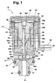
- Figures 1 and 2 each show one of the exemplary embodiments in longitudinal section, in FIGS. 3 and 4, the closing member 60 is enlarged as a single part shown.
- the proportional valves shown in Figures 1 and 2 10 each consist of a magnetic part 12 and one integrally connected to this valve part 14, the coaxial is arranged to the magnetic part 12.
- the magnetic part 12 comprises a coil 18 wound on a bobbin 16, the electrically controllable by means of lines 20 and contacts 22 is.
- the lines 20 are in a plastic part 24 injected in one piece with the bobbin 16 is connected and at the free end of the contacts 22 receiving connector housing 26 is provided.
- the coil 18 is hollow cylindrical and takes on a core 28 at its end facing the valve part 14 stationary on the sections of the inside of the coil 18th protrudes.
- This core 28 has a central Longitudinal bore 30 on the inside of the coil 18th located end in a flat depression 32.
- a guide sleeve 34 circumferential collar 34a At the bottom of the Flat countersink 32 is supported by a guide sleeve 34 circumferential collar 34a.
- the guide sleeve 34 has one Valve part 14 facing and in the longitudinal bore 30th of the core 28 extending neck 34b, the Inner wall at the end of the guide sleeve 34 on the valve part side forms an axial guide for a tappet 36.
- the latter is firmly connected to an anchor 38, which is on the Valve part 14 facing away from the end of the coil 18.
- the anchor 38 has the shape of a T and is divided into one the end face of the coil 18 covering head 38a and a shaft 38b projecting into the coil 18.
- the shaft 38b ends in a projection 38c, which extends into the flat depression 32 of the core 28 can dip.
- a secondary air gap 40 By a relative movement of the armature 38 with respect to the coil 18 to allow between the shaft 38b and Coil body 16 is a secondary air gap 40.
- a working air gap 41 which allows a lifting movement of the armature 38, is between the facing end faces of the armature 38 and the Kerns 28 recognizable.
- a spring washer 39 at the end facing away from the valve part 14 of the proportional valve 10.
- This spring washer 39 is in the Area of their outer circumference between a step of a Housing 42 of the magnetic part 12 and one of these housings 42 clamped to the outside cover 44.
- the lid 44 and the housing 42 are caulked together.
- Downtown the spring washer 39, a recess 46 is provided, the with a corresponding projection 38d of the armature 38 is also caulked.
- the housing 42 of the magnetic part 12 is essentially a coating of the Magnetic part 12 forming individual components with plastic generated. In this housing 42 is a flow guide metal sleeve 48 surrounding coil 18 is injected.
- the housing 42 of the proportional valve 10 goes into that Housing 43 of the valve part 14 over.
- a Inlet channel 50, a return channel 52 and a working channel 54 educated.
- the Inlet 50 and the return channel 52 are by means of ring seals 56 sealed against each other or to the outside.
- the inlet channel 50 is to form an orifice 57 in the flow direction once graduated in the inner diameter, is facing away from Magnetic part 12 and ends bluntly in the consumer channel 50 on.
- the valve part 14 faces horizontal return channel 52 as a continuous, i.e. the Working channel 54 penetrating, recess formed.
- the closing member 60 is divided into a cylindrical guide section 60a on the magnetic part side, an adjoining connecting section 60b and a sealing body 60c which interacts with the perforated diaphragm 55.
- the guide section 60a and the connecting section 60b have a cylindrical cross section
- the sealing body 60c is conical and, for reasons of flow technology, is curved outward in a dome-like manner on the end face of the valve part.
- the cross-section of the connecting section 60b has the shape of an annular groove with, for example, walls running at right angles to one another. This results in a flow separation edge 60d at the transition point from the sealing body 60c to the connecting section 60b, which significantly reduces the temperature sensitivity of the proportional valve 10.
- the closing member 60 is guided via the guides of the plunger 36 or the armature 38, separate guides 64 as are not necessary in the first embodiment.
Landscapes
- Engineering & Computer Science (AREA)
- General Engineering & Computer Science (AREA)
- Mechanical Engineering (AREA)
- Physics & Mathematics (AREA)
- Fluid Mechanics (AREA)
- Magnetically Actuated Valves (AREA)
- Control Of Transmission Device (AREA)
Claims (14)
- °) Soupape proportionnelle hydraulique (10) à commande électromagnétique comprenant une partie magnétique (12) formée d'une bobine (18) commandée électriquement, d'un noyau fixe (28) pénétrant à l'intérieur de la bobine (18) ainsi que d'un induit (38) sollicité par la bobine (18) et guidé de manière coulissante, l'induit étant couplé à un organe d'obturation (60),
une partie de soupape (14) comprenant au moins un canal d'alimentation (50), un canal de retour (52), un canal actif (54) et un siège de soupape (58) coopérant avec un organe d'obturation (60) pour commander la liaison de fluide sous pression entre le canal actif (54) et le canal de retour (52),
l'organe d'obturation (60) ayant un organe d'étanchéité (60c, 70) au moins dans la zone de son extrémité tournée vers le siège de soupape (58), cet organe d'étanchéité ayant un contour extérieur tronconique et la petite base de cet organe étant tournée vers le siège de soupape (58),
caractérisée en ce que
l'extrémité de l'organe d'étanchéité (60c, 70) à l'opposé du siège de soupape (58) forme une arête de décrochage de veine de fluide (60d) et cette arête de décrochage (60d) est formée par le contour extérieur tronconique de l'organe d'étanchéité (60c, 70) et une surface entourant de façon annulaire une pièce (62, 36) reliée à l'organe d'étanchéité (60c, 70) et coopérant avec l'induit (38) du côté de l'organe d'étanchéité (60c, 70) à l'opposé du siège de soupape (58). - Soupape proportionnelle hydraulique à commande électromagnétique selon la revendication 1,
caractérisée en ce que
l'arête de décrochage (60d) a des dimensions répondant aux deux relations mathématiques suivantes : - Soupape proportionnelle hydraulique à commande électromagnétique selon la revendication 1 ou 2,
caractérisée en ce que
l'organe d'étanchéité (60c, 70) présente une section en forme de pot avec une face frontale bombée de manière convexe, en forme de coupelle, tournée vers le siège de soupape (58). - Soupape proportionnelle hydraulique à commande électromagnétique selon l'une des revendications 1 à 3,
caractérisée en ce que
l'induit (38) agit par l'intermédiaire d'un poussoir (36) sur l'organe d'obturation (60) et
l'organe d'étanchéité (70) de l'organe d'obturation (60) est fixé à ce poussoir (36). - Soupape proportionnelle hydraulique à commande électromagnétique selon l'une des revendications 1 à 4,
caractérisée en ce qu'
en direction de la partie magnétique (12), l'organe d'étanchéité (60c) de l'organe d'obturation (60) se poursuit par un segment de liaison (60b) et ensuite une zone de guidage (60a). - Soupape proportionnelle hydraulique à commande électromagnétique selon la revendication 5,
caractérisée en ce que
la zone de guidage (60a) et le segment de liaison (60b) ont des sections cylindriques. - Soupape proportionnelle hydraulique à commande électromagnétique selon l'une des revendications 5 ou 6,
caractérisée en ce que
le segment de liaison (60b) est formé entre l'organe d'étanchéité (60c) et la zone de guidage (60a) de l'organe d'obturation (60) par une rainure annulaire à section essentiellement rectangulaire ou carrée. - Soupape proportionnelle hydraulique à commande électromagnétique selon l'une des revendications 5 à 7,
caractérisée en ce que
l'organe d'obturation (60) présente un perçage borgne (62) central, fermé au niveau de l'organe d'étanchéité (60c), et dans lequel pénètre un segment du poussoir (36). - Soupape proportionnelle hydraulique à commande électromagnétique selon l'une des revendications 5 à 8,
caractérisée en ce que
l'induit (38) agit par l'intermédiaire d'un poussoir (36) sur l'organe d'obturation (60) et entre cet organe d'obturation (60) et le poussoir (36) il y a une liaison active autorisant au moins un mouvement radial entre ces deux pièces. - Soupape proportionnelle hydraulique à commande électromagnétique selon l'une des revendications 1 à 9,
caractérisée en ce que
le siège de soupape (58) de la partie de soupape (14) est formée par un perçage dont l'embouchure est de forme rectangulaire au moins dans la zone de l'organe d'obturation (60). - Soupape proportionnelle hydraulique à commande électromagnétique selon l'une des revendications 1 à 10,
caractérisée en ce que
le siège de soupape (58) est formé en une matière résistante à l'usure au niveau d'un diaphragme (55) accroché dans la partie de soupape (14). - Soupape proportionnelle hydraulique à commande électromagnétique selon l'une des revendications 1 à 11,
caractérisée en ce que
la partie de soupape (14) est une pièce injectée en matière plastique. - Soupape proportionnelle hydraulique à commande électromagnétique selon l'une des revendications 1 à 12,
caractérisée en ce que
la partie magnétique (12) comprend un boítier (42) relié en une seule pièce au boítier (43) de la partie de soupape (14). - Boíte de vitesses automatique de véhicule automobile comportant des installations de commandes hydrauliques ayant au moins une soupape proportionnelle (10) selon l'une des revendications 1 à 13.
Applications Claiming Priority (3)
| Application Number | Priority Date | Filing Date | Title |
|---|---|---|---|
| DE19843781 | 1998-09-24 | ||
| DE19843781 | 1998-09-24 | ||
| PCT/DE1999/002850 WO2000017551A1 (fr) | 1998-09-24 | 1999-09-09 | Soupape proportionnelle hydraulique a actionnement electromagnetique |
Publications (2)
| Publication Number | Publication Date |
|---|---|
| EP1046005A1 EP1046005A1 (fr) | 2000-10-25 |
| EP1046005B1 true EP1046005B1 (fr) | 2004-06-16 |
Family
ID=7882071
Family Applications (1)
| Application Number | Title | Priority Date | Filing Date |
|---|---|---|---|
| EP99953718A Expired - Lifetime EP1046005B1 (fr) | 1998-09-24 | 1999-09-09 | Soupape proportionnelle hydraulique a actionnement electromagnetique |
Country Status (5)
| Country | Link |
|---|---|
| US (1) | US6378545B1 (fr) |
| EP (1) | EP1046005B1 (fr) |
| JP (1) | JP4658322B2 (fr) |
| DE (2) | DE19943066A1 (fr) |
| WO (1) | WO2000017551A1 (fr) |
Families Citing this family (27)
| Publication number | Priority date | Publication date | Assignee | Title |
|---|---|---|---|---|
| EP1099484B1 (fr) * | 1999-11-11 | 2006-06-07 | The Provost, Fellows And Scholars Of The College Of The Holy And Undivided Trinity Of Queen Elizabeth Near Dublin | Procédé et appareil de distribution de gouttes |
| DE10034959A1 (de) | 2000-07-19 | 2002-02-21 | Zahnradfabrik Friedrichshafen | Proportional-Druckregelventil |
| JP2002235842A (ja) * | 2001-02-13 | 2002-08-23 | Jatco Ltd | 自動変速機用ソレノイドバルブ回路 |
| US6669909B2 (en) * | 2001-03-26 | 2003-12-30 | Allegro Technologies Limited | Liquid droplet dispensing |
| DE10163235A1 (de) | 2001-12-21 | 2003-07-10 | Daimler Chrysler Ag | Elektromagnetventil, insbesondere für Automatikgetriebe |
| FR2837809B1 (fr) * | 2002-03-29 | 2004-11-12 | Manitou Bf | Chariot elevateur a portee variable a trois roues |
| JP4038452B2 (ja) * | 2003-04-18 | 2008-01-23 | 三菱電機株式会社 | 比例電磁弁 |
| JP2004324740A (ja) | 2003-04-23 | 2004-11-18 | Mitsubishi Electric Corp | 比例電磁弁及びその制御方法 |
| DE10342892B4 (de) | 2003-09-17 | 2014-07-31 | Zf Friedrichshafen Ag | Proportional-Druckregelventil |
| GB0324717D0 (en) * | 2003-10-22 | 2003-11-26 | Elopak Systems | A valve device for controlling liquid flow |
| US7475827B2 (en) * | 2005-04-19 | 2009-01-13 | Masco Corporation Of Indiana | Fluid mixer |
| US7458520B2 (en) * | 2005-04-19 | 2008-12-02 | Masco Corporation Of Indiana | Electronic proportioning valve |
| US7448553B2 (en) * | 2005-04-19 | 2008-11-11 | Masco Corporation Of Indiana | Fluid mixer |
| DE102005021902A1 (de) * | 2005-05-12 | 2006-11-16 | Zf Friedrichshafen Ag | Proportional-Druckregelventil zur Regelung des Druckniveaus in einem Hydraulikkreis, insbesondere in einem Hydraulikkreis eines Automatgetriebes |
| US7584898B2 (en) | 2005-07-01 | 2009-09-08 | Masco Corporation Of Indiana | Manual override for electronic proportioning valve |
| JP4734264B2 (ja) * | 2007-02-01 | 2011-07-27 | 日信工業株式会社 | 電磁弁 |
| RU2387905C1 (ru) * | 2008-12-29 | 2010-04-27 | Открытое акционерное общество "Информационные спутниковые системы" им. академика М.Ф. Решетнева" | Способ работы и устройство электромагнитного клапана высокого давления |
| DE102009000780A1 (de) * | 2009-02-11 | 2010-08-12 | Zf Friedrichshafen Ag | Kopplung zwischen einem Ventil und dem Aktuator zur Betätigung des Ventils |
| WO2011088273A2 (fr) | 2010-01-13 | 2011-07-21 | Dohrmann Daniel R | Pompe agricole à écoulement ultra-faible à voie d'écoulement non obstruée et commande d'écoulement électronique, indication de remplissage du réservoir et détection de perte d'écoulement |
| DE102010055033A1 (de) * | 2010-12-17 | 2012-06-21 | Pierburg Gmbh | Elektromagnetventil |
| DE102012208489A1 (de) * | 2011-06-20 | 2012-12-20 | Schaeffler Technologies AG & Co. KG | Hydrauliksystem |
| DE102011115898A1 (de) * | 2011-10-14 | 2013-04-18 | Svm Schultz Verwaltungs-Gmbh & Co. Kg | Elektromagnet |
| DE102013213713A1 (de) * | 2013-07-12 | 2015-01-29 | Zf Friedrichshafen Ag | Fluidventil |
| DE102014217441A1 (de) | 2014-09-01 | 2016-03-03 | Robert Bosch Gmbh | Elektromagnetisch betätigbares Proportionalventil |
| DE102015218371A1 (de) | 2015-09-24 | 2017-03-30 | Robert Bosch Gmbh | Elektromagnetisch betätigbares Proportionalventil |
| DE102018222614A1 (de) * | 2018-12-20 | 2020-06-25 | Robert Bosch Gmbh | Elektromagnetische Betätigungseinrichtung |
| CN113374917B (zh) * | 2021-06-30 | 2022-07-26 | 王颖颖 | 一种灵敏度高的比例阀 |
Family Cites Families (15)
| Publication number | Priority date | Publication date | Assignee | Title |
|---|---|---|---|---|
| DE76459C (de) * | F. BÖTE-FÜHR in Hamburg, Kleine Reichenstr. 3 | Zerlegbare Panzerdecke | ||
| FR1277797A (fr) * | 1961-01-18 | 1961-12-01 | Ranco Inc | Perfectionnements apportés aux vannes, notamment aux vannes électro-magnétiques |
| DE2105583A1 (de) * | 1971-02-06 | 1972-08-10 | Robert Bosch Gmbh, 7000 Stuttgart | Magnetventil zur Abgasrückführung bei Brennkraftmaschinen |
| JPS49106929U (fr) * | 1972-12-29 | 1974-09-12 | ||
| DE3139669A1 (de) * | 1981-10-06 | 1983-04-21 | Robert Bosch Gmbh, 7000 Stuttgart | Magnetventil, insbesondere kraftstoffeinspritzventil |
| JPH0348467Y2 (fr) * | 1988-09-21 | 1991-10-16 | ||
| JPH0328377U (fr) * | 1989-07-28 | 1991-03-20 | ||
| JPH0482460U (fr) * | 1990-11-28 | 1992-07-17 | ||
| DE4132816C2 (de) * | 1991-09-06 | 2002-06-13 | Bosch Gmbh Robert | Elektromagnetventil |
| DE4243179C2 (de) * | 1992-12-19 | 2001-08-16 | Bosch Gmbh Robert | Elektromagnetventil |
| DE4326507C2 (de) * | 1993-08-06 | 1996-06-05 | Bosch Gmbh Robert | Elektromagnetisch betätigbares Proportionalventil |
| US5611370A (en) * | 1994-11-10 | 1997-03-18 | Saturn Electronics & Engineering, Inc. | Proportional variable force solenoid control valve and transmission fluid control device |
| DE19503487A1 (de) * | 1995-02-03 | 1996-08-08 | Norbert Martin | Rückschlagventil |
| JPH09119550A (ja) * | 1995-10-26 | 1997-05-06 | Keihin Seiki Mfg Co Ltd | パルス駆動型電磁弁 |
| JP3245035B2 (ja) * | 1996-01-19 | 2002-01-07 | 三菱電機株式会社 | 空気制御バルブ |
-
1999
- 1999-09-09 EP EP99953718A patent/EP1046005B1/fr not_active Expired - Lifetime
- 1999-09-09 JP JP2000571168A patent/JP4658322B2/ja not_active Expired - Lifetime
- 1999-09-09 DE DE19943066A patent/DE19943066A1/de not_active Withdrawn
- 1999-09-09 US US09/555,103 patent/US6378545B1/en not_active Expired - Lifetime
- 1999-09-09 DE DE59909745T patent/DE59909745D1/de not_active Expired - Lifetime
- 1999-09-09 WO PCT/DE1999/002850 patent/WO2000017551A1/fr not_active Ceased
Also Published As
| Publication number | Publication date |
|---|---|
| EP1046005A1 (fr) | 2000-10-25 |
| WO2000017551A1 (fr) | 2000-03-30 |
| US6378545B1 (en) | 2002-04-30 |
| DE19943066A1 (de) | 2000-03-30 |
| DE59909745D1 (de) | 2004-07-22 |
| JP2002525524A (ja) | 2002-08-13 |
| JP4658322B2 (ja) | 2011-03-23 |
Similar Documents
| Publication | Publication Date | Title |
|---|---|---|
| EP1046005B1 (fr) | Soupape proportionnelle hydraulique a actionnement electromagnetique | |
| EP1004066B1 (fr) | Soupape hydraulique electromagnetique | |
| DE4211911C2 (de) | Magnetbetätigtes Druckregelventil | |
| EP0733005B1 (fr) | Electrovanne, en particulier pour systemes de freinage avec anti-patinage pour vehicules automobiles | |
| DE4211913C2 (de) | Magnetbetätigtes Druckregelventil | |
| DE60104168T2 (de) | Elektromagnetisches Druckregelventil | |
| DE4237681C2 (de) | Elektromagnetisch betätigbares Doppelsitzventil | |
| DE69715712T2 (de) | Hydraulisches Elektromagnetventil | |
| DE4231239A1 (de) | Vorrichtung zur Regelung der Leerlaufdrehzahl einer Brennkraftmaschine | |
| DE3823430C3 (de) | Hydraulischer Teleskopstoßdämpfer | |
| DE19504077A1 (de) | Magnetventil mit Druckbegrenzung für schlupfgeregelte Kraftfahrzeug-Bremsanlagen | |
| EP1700058B1 (fr) | Soupape de commande d'un fluide | |
| DE68916435T2 (de) | Schnell ansprechendes, druckausgeglichenes, elektromagnetisches hochdruck-steuerventil. | |
| DE10104622B4 (de) | Hydraulisches Druckregelventil | |
| DE4324589C2 (de) | Elektromagnetisch betätigbares Druckregelventil | |
| DE10024700A1 (de) | Vorrichtung zur Regelung des Drucks in einem Hydraulikkreis | |
| EP3189289B1 (fr) | Détendeur à commande électromagnétique | |
| DE10353840B4 (de) | Proportional-Magnetventil | |
| DE2658969A1 (de) | Druckregelventil | |
| DE3636409A1 (de) | Druckregelventil | |
| DE69203374T2 (de) | Hydraulischer Stossdämpfer. | |
| DE19738633B4 (de) | Elektromagnetisches Schaltventil | |
| EP0099991B1 (fr) | Buse d'injection de carburant pour moteurs à combustion interne | |
| DE19510647C1 (de) | Elektromagnetisch betätigbares Druckregelventil und Verfahren zu dessen Herstellung | |
| DE69008266T2 (de) | Elektromagnetisches Ventil. |
Legal Events
| Date | Code | Title | Description |
|---|---|---|---|
| PUAI | Public reference made under article 153(3) epc to a published international application that has entered the european phase |
Free format text: ORIGINAL CODE: 0009012 |
|
| AK | Designated contracting states |
Kind code of ref document: A1 Designated state(s): AT BE CH CY DE DK ES FI FR GB GR IE IT LI LU MC NL PT SE |
|
| 17P | Request for examination filed |
Effective date: 20001002 |
|
| 17Q | First examination report despatched |
Effective date: 20030227 |
|
| GRAP | Despatch of communication of intention to grant a patent |
Free format text: ORIGINAL CODE: EPIDOSNIGR1 |
|
| GRAS | Grant fee paid |
Free format text: ORIGINAL CODE: EPIDOSNIGR3 |
|
| GRAA | (expected) grant |
Free format text: ORIGINAL CODE: 0009210 |
|
| AK | Designated contracting states |
Kind code of ref document: B1 Designated state(s): DE FR GB IT SE |
|
| REG | Reference to a national code |
Ref country code: GB Ref legal event code: FG4D Free format text: NOT ENGLISH |
|
| REF | Corresponds to: |
Ref document number: 59909745 Country of ref document: DE Date of ref document: 20040722 Kind code of ref document: P |
|
| REG | Reference to a national code |
Ref country code: IE Ref legal event code: FG4D Free format text: GERMAN |
|
| REG | Reference to a national code |
Ref country code: SE Ref legal event code: TRGR |
|
| PGFP | Annual fee paid to national office [announced via postgrant information from national office to epo] |
Ref country code: GB Payment date: 20040826 Year of fee payment: 6 |
|
| PGFP | Annual fee paid to national office [announced via postgrant information from national office to epo] |
Ref country code: FR Payment date: 20040917 Year of fee payment: 6 |
|
| PGFP | Annual fee paid to national office [announced via postgrant information from national office to epo] |
Ref country code: SE Payment date: 20040924 Year of fee payment: 6 |
|
| GBT | Gb: translation of ep patent filed (gb section 77(6)(a)/1977) |
Effective date: 20040906 |
|
| ET | Fr: translation filed | ||
| REG | Reference to a national code |
Ref country code: IE Ref legal event code: FD4D |
|
| PLBE | No opposition filed within time limit |
Free format text: ORIGINAL CODE: 0009261 |
|
| STAA | Information on the status of an ep patent application or granted ep patent |
Free format text: STATUS: NO OPPOSITION FILED WITHIN TIME LIMIT |
|
| 26N | No opposition filed |
Effective date: 20050317 |
|
| PG25 | Lapsed in a contracting state [announced via postgrant information from national office to epo] |
Ref country code: IT Free format text: LAPSE BECAUSE OF NON-PAYMENT OF DUE FEES Effective date: 20050909 Ref country code: GB Free format text: LAPSE BECAUSE OF NON-PAYMENT OF DUE FEES Effective date: 20050909 |
|
| PG25 | Lapsed in a contracting state [announced via postgrant information from national office to epo] |
Ref country code: SE Free format text: LAPSE BECAUSE OF NON-PAYMENT OF DUE FEES Effective date: 20050910 |
|
| EUG | Se: european patent has lapsed | ||
| GBPC | Gb: european patent ceased through non-payment of renewal fee |
Effective date: 20050909 |
|
| PG25 | Lapsed in a contracting state [announced via postgrant information from national office to epo] |
Ref country code: FR Free format text: LAPSE BECAUSE OF NON-PAYMENT OF DUE FEES Effective date: 20060531 |
|
| REG | Reference to a national code |
Ref country code: FR Ref legal event code: ST Effective date: 20060531 |
|
| PGFP | Annual fee paid to national office [announced via postgrant information from national office to epo] |
Ref country code: DE Payment date: 20131121 Year of fee payment: 15 |
|
| REG | Reference to a national code |
Ref country code: DE Ref legal event code: R119 Ref document number: 59909745 Country of ref document: DE |
|
| REG | Reference to a national code |
Ref country code: DE Ref legal event code: R119 Ref document number: 59909745 Country of ref document: DE Effective date: 20150401 |
|
| PG25 | Lapsed in a contracting state [announced via postgrant information from national office to epo] |
Ref country code: DE Free format text: LAPSE BECAUSE OF NON-PAYMENT OF DUE FEES Effective date: 20150401 |