EP1046047B1 - Element detecteur magnetoresistif avec possibilite de choisir le sens d'aimantation de la couche de polarisation - Google Patents
Element detecteur magnetoresistif avec possibilite de choisir le sens d'aimantation de la couche de polarisation Download PDFInfo
- Publication number
- EP1046047B1 EP1046047B1 EP99936399A EP99936399A EP1046047B1 EP 1046047 B1 EP1046047 B1 EP 1046047B1 EP 99936399 A EP99936399 A EP 99936399A EP 99936399 A EP99936399 A EP 99936399A EP 1046047 B1 EP1046047 B1 EP 1046047B1
- Authority
- EP
- European Patent Office
- Prior art keywords
- layer
- sensor element
- magnetization direction
- sensor
- magnetic field
- Prior art date
- Legal status (The legal status is an assumption and is not a legal conclusion. Google has not performed a legal analysis and makes no representation as to the accuracy of the status listed.)
- Expired - Lifetime
Links
- 230000005415 magnetization Effects 0.000 title claims abstract description 46
- 230000005291 magnetic effect Effects 0.000 claims abstract description 42
- 239000004020 conductor Substances 0.000 claims description 11
- 239000000696 magnetic material Substances 0.000 claims description 6
- 238000000034 method Methods 0.000 claims description 6
- 239000012212 insulator Substances 0.000 claims description 3
- 238000001514 detection method Methods 0.000 description 9
- 230000001419 dependent effect Effects 0.000 description 5
- 230000000694 effects Effects 0.000 description 5
- 230000006978 adaptation Effects 0.000 description 2
- 230000005290 antiferromagnetic effect Effects 0.000 description 2
- 239000000463 material Substances 0.000 description 2
- 238000005259 measurement Methods 0.000 description 2
- 239000000758 substrate Substances 0.000 description 2
- 239000010409 thin film Substances 0.000 description 2
- 238000002485 combustion reaction Methods 0.000 description 1
- 238000010276 construction Methods 0.000 description 1
- 230000008878 coupling Effects 0.000 description 1
- 238000010168 coupling process Methods 0.000 description 1
- 238000005859 coupling reaction Methods 0.000 description 1
- 230000006378 damage Effects 0.000 description 1
- 230000006735 deficit Effects 0.000 description 1
- 238000010586 diagram Methods 0.000 description 1
- 230000005389 magnetism Effects 0.000 description 1
- 230000035945 sensitivity Effects 0.000 description 1
Images


Classifications
-
- G—PHYSICS
- G01—MEASURING; TESTING
- G01D—MEASURING NOT SPECIALLY ADAPTED FOR A SPECIFIC VARIABLE; ARRANGEMENTS FOR MEASURING TWO OR MORE VARIABLES NOT COVERED IN A SINGLE OTHER SUBCLASS; TARIFF METERING APPARATUS; MEASURING OR TESTING NOT OTHERWISE PROVIDED FOR
- G01D5/00—Mechanical means for transferring the output of a sensing member; Means for converting the output of a sensing member to another variable where the form or nature of the sensing member does not constrain the means for converting; Transducers not specially adapted for a specific variable
- G01D5/12—Mechanical means for transferring the output of a sensing member; Means for converting the output of a sensing member to another variable where the form or nature of the sensing member does not constrain the means for converting; Transducers not specially adapted for a specific variable using electric or magnetic means
- G01D5/14—Mechanical means for transferring the output of a sensing member; Means for converting the output of a sensing member to another variable where the form or nature of the sensing member does not constrain the means for converting; Transducers not specially adapted for a specific variable using electric or magnetic means influencing the magnitude of a current or voltage
- G01D5/142—Mechanical means for transferring the output of a sensing member; Means for converting the output of a sensing member to another variable where the form or nature of the sensing member does not constrain the means for converting; Transducers not specially adapted for a specific variable using electric or magnetic means influencing the magnitude of a current or voltage using Hall-effect devices
- G01D5/145—Mechanical means for transferring the output of a sensing member; Means for converting the output of a sensing member to another variable where the form or nature of the sensing member does not constrain the means for converting; Transducers not specially adapted for a specific variable using electric or magnetic means influencing the magnitude of a current or voltage using Hall-effect devices influenced by the relative movement between the Hall device and magnetic fields
-
- B—PERFORMING OPERATIONS; TRANSPORTING
- B82—NANOTECHNOLOGY
- B82Y—SPECIFIC USES OR APPLICATIONS OF NANOSTRUCTURES; MEASUREMENT OR ANALYSIS OF NANOSTRUCTURES; MANUFACTURE OR TREATMENT OF NANOSTRUCTURES
- B82Y25/00—Nanomagnetism, e.g. magnetoimpedance, anisotropic magnetoresistance, giant magnetoresistance or tunneling magnetoresistance
-
- G—PHYSICS
- G01—MEASURING; TESTING
- G01B—MEASURING LENGTH, THICKNESS OR SIMILAR LINEAR DIMENSIONS; MEASURING ANGLES; MEASURING AREAS; MEASURING IRREGULARITIES OF SURFACES OR CONTOURS
- G01B7/00—Measuring arrangements characterised by the use of electric or magnetic techniques
- G01B7/30—Measuring arrangements characterised by the use of electric or magnetic techniques for measuring angles or tapers; for testing the alignment of axes
-
- G—PHYSICS
- G01—MEASURING; TESTING
- G01R—MEASURING ELECTRIC VARIABLES; MEASURING MAGNETIC VARIABLES
- G01R33/00—Arrangements or instruments for measuring magnetic variables
- G01R33/02—Measuring direction or magnitude of magnetic fields or magnetic flux
- G01R33/06—Measuring direction or magnitude of magnetic fields or magnetic flux using galvano-magnetic devices
- G01R33/09—Magnetoresistive devices
- G01R33/093—Magnetoresistive devices using multilayer structures, e.g. giant magnetoresistance sensors
Definitions
- the present invention relates to a magnetoresistive sensor element, in particular an angle sensor element, according to the preamble of patent claim 1 and to a method for determining a direction of a magnetic field according to the preamble of patent claim 6.
- Sensors in particular angle sensors, which operate on the basis of the magnetoresistive effect are known.
- the electrical resistance of sensor elements is measured as a function of the direction of an external magnetic field.
- AMR sensors so-called AMR sensors.
- GMR sensor elements English: giant magneto-resistance effect
- self-stabilizing Magnetic layers van den Berg et al., GMR angle detector with an artificial antiferromagnetic subsystem, Journal of Magnetism and Magnetic Materials 165 (1997) 524-528).
- a first thin, so-called reference layer is produced by introducing an antiferromagnetic coupling layer (for example made of Cu or Ru) between two oppositely magnetized layers (for example from Co).
- the magnetic stability of the reference layer is increased by about one order of magnitude compared to individual Co layers due to this multilayer structure.
- the magnetization direction of the reference layer, the so-called reference direction does not depend (ideally) on the direction of the external (to be measured) magnetic field.
- a magnetization device for a magnetoresistive thin-film sensor element with a bias layer part is known.
- the magnetization distribution of the bias layer part of a sensor element is to be impressed.
- This element has a thin film structure on a substrate and exhibits an increased magnetoresistive effect.
- the device should contain an electrically conductive trace part and means for positioning this trace part with respect to the sensor element. In this case, a predetermined setting current is to be conducted via the conductor track part, so that the predetermined magnetization distribution can be fixed in the bias layer part of the sensor element.
- the reference layer is covered with a thin non-magnetic layer, on which in turn a thin soft magnetic layer, the so-called detection layer, is formed.
- Such AMR or. GMR sensors can only be used with great effort as 360 ° angle sensors.
- GMR materials When GMR materials are used, it is also found that the sensor function is destroyed in the event of excessive magnetic fields.
- Hall-based angle sensor elements are known, which, however, can usually cover only an angular range of 120 °.
- the object of the invention is therefore to provide a sensor, in particular an angle sensor, with which the deployment effort or the measurement effort during operation compared to conventional sensors can be reduced.
- a sensor element or a sensor is now provided which, compared with conventional devices of this type, has a much simpler and less expensive construction to be realized.
- An interconnection of a number of sensor elements is now no longer necessary, an angle to be measured in a simple way with only be determined a sensor element. This eliminates a costly application of multiple sensor elements on a substrate. Offset and sensitivity of the sensor element are improved, since no adjustment of different sensor elements must be performed.
- Preferred fields of application for the sensor element according to the invention are steering wheel angle encoders for driving dynamics control of motor vehicles, camshaft signal generators, for example for controlling an engine direct start, DVE throttle adjustment units or sunroof controllers.
- the different reference directions are offset by 90 ° from each other.
- linearly independent signals in particular the sine and cosine of the direction of rotation of the external magnetic field
- the direction of rotation or the angle of the external magnetic field with respect to an excellent direction for example one of the two reference directions, can then be determined in a known manner with little effort.
- the means for selectively aligning the direction of magnetization are formed by a current conductor, which is galvanically separated from the first layer by means of an insulator layer and designed to conduct current in different directions, in particular directions offset by 90 ° from one another.
- a so-called bias current With such a so-called bias current, the selective alignment of the magnetization direction can be achieved in a simple and reliable manner.
- the bias current is constant in time or can be controlled continuously in a simple manner. Since no hard magnetic material has to be used to provide the reference magnetization, according to the invention, no impairment or destruction of the sensor function occurs in the case of strong magnetic fields.
- Such sensor elements have a wide temperature range of application and can be used in particular for motor vehicles.
- the first layer is made of a soft magnetic material.
- a soft magnetic material Such materials are available inexpensively and by means of a current-induced magnetic field (Biasstrom) magnetizable.
- the third layer, the detection layer of the sensor element made of a soft magnetic material.
- the detection layer of the sensor element made of a soft magnetic material.
- one of the sensor signals is a sinusoid of the angle between the first reference direction and the magnetization direction of the third layer, and in another of the sensor signals a cosine of the angle between the second reference direction and the Magnetization direction of the third layer associated signal.
- Such signals can be evaluated in a simple manner, in particular using the Arctan function.
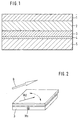
- FIG. 1 schematically shows a preferred layer structure of a sensor element according to the invention.
- the sensor element has a thin magnetic, preferably soft magnetic, layer 3 (reference layer 3).
- the magnetization direction of this reference layer 3 represents the reference direction of the sensor element.
- Applied to the reference layer 3 is a thin, nonmagnetic conductor layer 2 on which a further, preferably soft magnetic layer 1 (detection layer) is applied. is trained.
- the direction of magnetization of this detection layer 1 is dependent on the direction of an external magnetic field B (oriented parallel to the layer surface), as will be explained in detail below.
- an insulator layer 4 is formed, which electrically separates the reference layer 3 from a layer 5 formed as a current conductor. Depending on the current direction in the current conductor layer 5, a magnetic field is induced in the reference layer 3, which leads to a corresponding magnetization of the reference layer 3.
- FIG. 6 The relationship between the direction of current in the layer 5 and the induced magnetization in the reference layer 3 is shown in FIG. If a current Is flowing in the horizontal direction according to the illustration of FIG. 6, a magnetization corresponding to the direction represented by the arrow Ms is induced in the reference layer 3, which is arranged above it and not shown in FIG. In the case of a current flow Ic perpendicular thereto, a magnetization in the direction of the arrow Mc results analogously. For the sake of simplicity, both the magnetization directions or directions of magnetic field arrows, and the corresponding magnetizations or magnetic fields will be referred to in the following.
- FIG. 5 A preferred control of the conductor layer 5 is shown in FIG. It can be seen that the current conductor layer 5 is applied alternately with the mutually perpendicular currents Is, Ic.
- FIG. 2 shows the magnetization Ms of the reference layer 3 when the current Is is applied.
- arrow Ms points into the drawing plane.
- the direction of the external magnetic field to be measured is shown by the arrow B.
- the magnetic field B causes a corresponding magnetization in the detection layer 1, whose direction is indicated by the arrow Md.
- the magnetic field B and the magnetization Md of the detection layer have the same orientation.
- the arrow Mc which represents the direction of magnetization of the reference layer 3 points in a direction parallel to the plane of the drawing. This magnetization is, as already explained, caused by the current Ic in the current conductor layer 5.
- a voltage signal generated by the sensor element is dependent on the relative orientation of the magnetizations Ms, Md or Mc, Md (for example when the magnetic field B is rotating).
- Ms the relative orientation of the magnetizations Ms, Md or Mc, Md (for example when the magnetic field B is rotating).
- Mc the reference-layer magnetization
- FIG. 4 the reference-layer magnetization Mc in Figure 5 shown.
- the magnetization Md is indicated by means of a large arrowhead
- FIGS Magnetizations Ms and Mc shown by means of small arrowheads.
- FIG. 4 shows a sinusoidal dependence of the sensor signal on the angle between the magnetizations Md and Ms, in accordance with FIG. 5 a cosinusoid dependence between the magnetizations Md and Mc.
- a throttle valve 31 provided in an intake pipe 30 of an internal combustion engine has a magnet 32 on an extension formed outside the intake pipe, which generates a magnetic field B corresponding to its orientation dependent on the position of the throttle valve.
- this magnetic field B is a schematically represented (strong enlarged) GMR sensor element 33, which has a structure and an operation as shown above.
- the magnetic field B is aligned parallel to the surface of the sensor element 33 (or to its detection layer, not shown).
Landscapes
- Physics & Mathematics (AREA)
- General Physics & Mathematics (AREA)
- Chemical & Material Sciences (AREA)
- Engineering & Computer Science (AREA)
- Nanotechnology (AREA)
- Condensed Matter Physics & Semiconductors (AREA)
- Crystallography & Structural Chemistry (AREA)
- Measuring Magnetic Variables (AREA)
- Hall/Mr Elements (AREA)
- Transmission And Conversion Of Sensor Element Output (AREA)
- Magnetic Heads (AREA)
- Measurement Of Length, Angles, Or The Like Using Electric Or Magnetic Means (AREA)
Abstract
Claims (7)
- Élément détecteur magnétorésistif, notamment élément détecteur d'angle, comprenant une première couche (3) magnétique, dont la direction d'aimantation représente une direction de référence, une deuxième couche (2) non magnétique constituée sur la première couche (3), et une troisième couche (1) magnétique constituée sur la deuxième couche (2) et dont la direction d'aimantation peut être influencée par un champ magnétique extérieur,
caractérisé par
des moyens (5) pour l'orientation alternée, différente de la direction d'aimantation de la première couche (3) pour créer des directions de référence différentes, décalées les unes par rapport aux autres. - Élément détecteur selon la revendication 1,
caractérisé en ce que
les différentes directions de référence sont décalées les unes par rapport aux autres de 90°. - Élément détecteur selon l'une des revendications 1 ou 2,
caractérisé en ce que
les moyens (5) sont formés par un conducteur galvaniquement séparé de la première couche (3) par une couche d'isolateur (4), et qui pour la conduction du courant est réalisé dans différentes directions, notamment dans des directions décalées de 90° les unes par rapport aux autres. - Élément détecteur selon l'une quelconque des revendications précédentes,
caractérisé en ce que
la première couche (3) est fabriquée en un matériau magnétique doux. - Élément détecteur selon l'une quelconque des revendications précédentes,
caractérisé en ce que
la troisième couche (1) est fabriquée à partir d'un matériau magnétique doux. - Procédé de détermination d'une direction d'un champ magnétique en utilisant un élément détecteur selon l'une quelconque des revendications ci-dessus,
caractérisé en ce qu'
on crée des directions de référence différentes en alternance dans la première couche (3) de l'élément détecteur par les moyens (5), un signal détecteur étant calculé pour chaque direction de référence en fonction d'un angle entre la direction de référence concernée et une direction d'aimantation de la troisième couche (1) de l'élément capteur induite par le champ magnétique. - Procédé selon la revendication 6,
caractérisé en ce que
l'un des signaux détecteurs est un signal détecteur associé au sinus de l'angle entre la première direction de référence et la direction d'aimantation de la troisième couche (1), et l'autre signal parmi les signaux détecteurs, est un signal associé au cosinus de l'angle entre la deuxième direction de référence et la direction d'aimantation de la troisième couche (1).
Applications Claiming Priority (3)
| Application Number | Priority Date | Filing Date | Title |
|---|---|---|---|
| DE19843348 | 1998-09-22 | ||
| DE19843348A DE19843348A1 (de) | 1998-09-22 | 1998-09-22 | Magnetoresistives Sensorelement, insbesondere Winkelsensorelement |
| PCT/DE1999/001631 WO2000017667A1 (fr) | 1998-09-22 | 1999-06-02 | Element detecteur magnetoresistif avec possibilite de choisir le sens d'aimantation de la couche de polarisation |
Publications (2)
| Publication Number | Publication Date |
|---|---|
| EP1046047A1 EP1046047A1 (fr) | 2000-10-25 |
| EP1046047B1 true EP1046047B1 (fr) | 2006-06-07 |
Family
ID=7881777
Family Applications (1)
| Application Number | Title | Priority Date | Filing Date |
|---|---|---|---|
| EP99936399A Expired - Lifetime EP1046047B1 (fr) | 1998-09-22 | 1999-06-02 | Element detecteur magnetoresistif avec possibilite de choisir le sens d'aimantation de la couche de polarisation |
Country Status (8)
| Country | Link |
|---|---|
| US (1) | US6373247B1 (fr) |
| EP (1) | EP1046047B1 (fr) |
| JP (1) | JP2002525610A (fr) |
| KR (1) | KR100606584B1 (fr) |
| AU (1) | AU759610B2 (fr) |
| DE (2) | DE19843348A1 (fr) |
| TW (1) | TW440704B (fr) |
| WO (1) | WO2000017667A1 (fr) |
Families Citing this family (23)
| Publication number | Priority date | Publication date | Assignee | Title |
|---|---|---|---|---|
| DE10230455A1 (de) | 2002-07-06 | 2004-01-22 | Robert Bosch Gmbh | Verfahren zur Einstellung oder lokalen Veränderung einer Magnetisierung in einer Schicht einer magnetoresistiven Schichtanordnung, Heizstempel zum Anheizen der magnetoresistiven Schichtanordnung und deren Verwendung |
| RU2328015C2 (ru) | 2002-07-26 | 2008-06-27 | Роберт Бош Гмбх | Чувствительный элемент с гигантской магниторезистивностью и его применение |
| US7504824B2 (en) * | 2004-10-21 | 2009-03-17 | International Business Machines Corporation | Magnetic sensor with offset magnetic field |
| JP2006269955A (ja) * | 2005-03-25 | 2006-10-05 | Mitsubishi Electric Corp | 磁界検出装置 |
| KR100668488B1 (ko) * | 2005-06-21 | 2007-01-15 | 대성전기공업 주식회사 | 자동차 조향장치용 각속도 감지장치 |
| US8665113B2 (en) * | 2005-10-31 | 2014-03-04 | Wavetronix Llc | Detecting roadway targets across beams including filtering computed positions |
| JP4607049B2 (ja) * | 2006-02-23 | 2011-01-05 | 株式会社デンソー | 回転角検出装置 |
| JP2011127909A (ja) * | 2009-12-15 | 2011-06-30 | Alps Electric Co Ltd | 回転検出システム |
| PL2572403T3 (pl) | 2010-05-19 | 2019-02-28 | Saint-Gobain Glass France | Antena zoptymalizowana pod względem szerokości pasma z konstrukcją hybrydową z promienników powierzchniowych i liniowych |
| US9310446B2 (en) * | 2012-10-18 | 2016-04-12 | Analog Devices, Inc. | Magnetic field direction detector |
| US9377327B2 (en) * | 2013-06-28 | 2016-06-28 | Analog Devices Global | Magnetic field direction sensor |
| US9529060B2 (en) | 2014-01-09 | 2016-12-27 | Allegro Microsystems, Llc | Magnetoresistance element with improved response to magnetic fields |
| US9812637B2 (en) | 2015-06-05 | 2017-11-07 | Allegro Microsystems, Llc | Spin valve magnetoresistance element with improved response to magnetic fields |
| CN205066678U (zh) | 2015-10-26 | 2016-03-02 | 深圳市道通智能航空技术有限公司 | 角位移检测装置、电机转角控制系统、云台和飞行器 |
| JP6430565B2 (ja) | 2016-03-23 | 2018-11-28 | アナログ・デヴァイシズ・グローバル | 磁界検出器 |
| US10620279B2 (en) | 2017-05-19 | 2020-04-14 | Allegro Microsystems, Llc | Magnetoresistance element with increased operational range |
| US11022661B2 (en) | 2017-05-19 | 2021-06-01 | Allegro Microsystems, Llc | Magnetoresistance element with increased operational range |
| US10739165B2 (en) | 2017-07-05 | 2020-08-11 | Analog Devices Global | Magnetic field sensor |
| CN112556569B (zh) * | 2020-11-17 | 2022-05-31 | 西人马帝言(北京)科技有限公司 | 传感器温度补偿的方法、装置、设备及存储介质 |
| US11719771B1 (en) | 2022-06-02 | 2023-08-08 | Allegro Microsystems, Llc | Magnetoresistive sensor having seed layer hysteresis suppression |
| US12320870B2 (en) | 2022-07-19 | 2025-06-03 | Allegro Microsystems, Llc | Controlling out-of-plane anisotropy in an MR sensor with free layer dusting |
| US12359904B2 (en) | 2023-01-26 | 2025-07-15 | Allegro Microsystems, Llc | Method of manufacturing angle sensors including magnetoresistance elements including different types of antiferromagnetic materials |
| US12352832B2 (en) | 2023-01-30 | 2025-07-08 | Allegro Microsystems, Llc | Reducing angle error in angle sensor due to orthogonality drift over magnetic-field |
Family Cites Families (4)
| Publication number | Priority date | Publication date | Assignee | Title |
|---|---|---|---|---|
| DE19520172A1 (de) * | 1995-06-01 | 1996-12-05 | Siemens Ag | Magnetisierungseinrichtung für ein magnetoresistives Dünnschicht-Sensorelement mit einem Biasschichtteil |
| US5648885A (en) * | 1995-08-31 | 1997-07-15 | Hitachi, Ltd. | Giant magnetoresistive effect sensor, particularly having a multilayered magnetic thin film layer |
| JPH09126780A (ja) * | 1995-10-31 | 1997-05-16 | Tokin Corp | 磁気方位センサ |
| JP3461999B2 (ja) * | 1996-03-28 | 2003-10-27 | 株式会社東芝 | 磁気抵抗効果素子 |
-
1998
- 1998-09-22 DE DE19843348A patent/DE19843348A1/de not_active Ceased
-
1999
- 1999-06-02 EP EP99936399A patent/EP1046047B1/fr not_active Expired - Lifetime
- 1999-06-02 JP JP2000571277A patent/JP2002525610A/ja active Pending
- 1999-06-02 WO PCT/DE1999/001631 patent/WO2000017667A1/fr not_active Ceased
- 1999-06-02 DE DE59913523T patent/DE59913523D1/de not_active Expired - Lifetime
- 1999-06-02 AU AU51516/99A patent/AU759610B2/en not_active Ceased
- 1999-06-02 US US09/530,699 patent/US6373247B1/en not_active Expired - Fee Related
- 1999-06-02 KR KR1020007005473A patent/KR100606584B1/ko not_active Expired - Fee Related
- 1999-06-07 TW TW088109404A patent/TW440704B/zh not_active IP Right Cessation
Also Published As
| Publication number | Publication date |
|---|---|
| US6373247B1 (en) | 2002-04-16 |
| KR20010032267A (ko) | 2001-04-16 |
| DE59913523D1 (de) | 2006-07-20 |
| AU759610B2 (en) | 2003-04-17 |
| AU5151699A (en) | 2000-04-10 |
| DE19843348A1 (de) | 2000-03-23 |
| EP1046047A1 (fr) | 2000-10-25 |
| WO2000017667A1 (fr) | 2000-03-30 |
| KR100606584B1 (ko) | 2006-08-01 |
| TW440704B (en) | 2001-06-16 |
| JP2002525610A (ja) | 2002-08-13 |
Similar Documents
| Publication | Publication Date | Title |
|---|---|---|
| EP1046047B1 (fr) | Element detecteur magnetoresistif avec possibilite de choisir le sens d'aimantation de la couche de polarisation | |
| DE19729808C2 (de) | Sensoreinrichtung | |
| DE19647320C2 (de) | Magnetfeld-Fühler zum Detektieren der Veränderung eines Magnetfelds | |
| EP0226574B1 (fr) | Detecteur a magnetoresistance pour la production de signaux electriques | |
| EP1049908B1 (fr) | Configuration destinee a la detection de l'angle de rotation d'un element rotatif | |
| DE19851839B4 (de) | Magnetfelddetektor | |
| DE19539722C2 (de) | Vorrichtung zur Erfassung einer Änderung eines Winkels oder der Feldstärke eines magnetischen Feldes | |
| DE19649400C5 (de) | Magnetfeld-Fühler | |
| EP0990120A1 (fr) | Capteur angulaire et procede de determination d'un angle | |
| EP1567878B1 (fr) | Element de detection magnetoresistif et procede pour diminuer le defaut d'alignement angulaire d'un element de detection magnetoresistif | |
| DE102007013755A1 (de) | Indikatorelement für einen magnetischen Drehwinkelgeber | |
| DE102005022596A1 (de) | Anordnung zur eigensicheren Raddrehzahlerfassung | |
| WO1986000986A1 (fr) | Dispositif sensible magnetoresistif pour mesurer des variations du champ magnetique et procede pour le fabriquer | |
| DE19647420B4 (de) | Vorrichtung zum Erfassen eines Magnetfelds | |
| EP1399750A1 (fr) | Ensemble de couches magnetoresistif et gradiometre comportant un ensemble de couches de ce type | |
| DE19612422C2 (de) | Potentiometereinrichtung mit einem linear verschiebbaren Stellelement und signalerzeugenden Mitteln | |
| DE19642752B4 (de) | Meßgerät zur Feststellung der Änderung eines Magnetfeldes | |
| DE19949714A1 (de) | Magnetisch sensitives Bauteil, insbesondere Sensorelement, mit magnetoresistiven Schichtsystemen in Brückenschaltung | |
| DE19851323B4 (de) | Magnetischer Detektor | |
| DE10117355A1 (de) | Verfahren zur Einstellung einer Magnetisierung in einer Schichtanordnung und dessen Verwendung | |
| DE10257253A1 (de) | GMR-Sensorelement und dessen Verwendung | |
| DE10250319A1 (de) | Einrichtung zur Erfassung der Rotation einer Welle und GMR-Schichtsystem | |
| DE10222467A1 (de) | GMR-Drehwinkelsensor | |
| EP0873497B1 (fr) | Dispositif de detection de deviations d'un corps magnetique | |
| EP1348974A2 (fr) | Elément capteur et dispositif de mesure des gradients, application à la mesure des gradients magnétique et méthode correspondante |
Legal Events
| Date | Code | Title | Description |
|---|---|---|---|
| PUAI | Public reference made under article 153(3) epc to a published international application that has entered the european phase |
Free format text: ORIGINAL CODE: 0009012 |
|
| AK | Designated contracting states |
Kind code of ref document: A1 Designated state(s): DE FR GB IT |
|
| 17P | Request for examination filed |
Effective date: 20001002 |
|
| RIN1 | Information on inventor provided before grant (corrected) |
Inventor name: FREITAG, MARTIN Inventor name: JOST, FRANZ Inventor name: KITTEL, HARTMUT Inventor name: MARX, KLAUS |
|
| 17Q | First examination report despatched |
Effective date: 20050607 |
|
| GRAP | Despatch of communication of intention to grant a patent |
Free format text: ORIGINAL CODE: EPIDOSNIGR1 |
|
| GRAS | Grant fee paid |
Free format text: ORIGINAL CODE: EPIDOSNIGR3 |
|
| GRAA | (expected) grant |
Free format text: ORIGINAL CODE: 0009210 |
|
| AK | Designated contracting states |
Kind code of ref document: B1 Designated state(s): DE FR GB IT |
|
| REG | Reference to a national code |
Ref country code: GB Ref legal event code: FG4D Free format text: NOT ENGLISH |
|
| REF | Corresponds to: |
Ref document number: 59913523 Country of ref document: DE Date of ref document: 20060720 Kind code of ref document: P |
|
| GBT | Gb: translation of ep patent filed (gb section 77(6)(a)/1977) |
Effective date: 20060927 |
|
| ET | Fr: translation filed | ||
| PLBE | No opposition filed within time limit |
Free format text: ORIGINAL CODE: 0009261 |
|
| STAA | Information on the status of an ep patent application or granted ep patent |
Free format text: STATUS: NO OPPOSITION FILED WITHIN TIME LIMIT |
|
| 26N | No opposition filed |
Effective date: 20070308 |
|
| PGFP | Annual fee paid to national office [announced via postgrant information from national office to epo] |
Ref country code: FR Payment date: 20100706 Year of fee payment: 12 |
|
| PGFP | Annual fee paid to national office [announced via postgrant information from national office to epo] |
Ref country code: IT Payment date: 20100624 Year of fee payment: 12 |
|
| PGFP | Annual fee paid to national office [announced via postgrant information from national office to epo] |
Ref country code: GB Payment date: 20100401 Year of fee payment: 12 Ref country code: DE Payment date: 20100824 Year of fee payment: 12 |
|
| GBPC | Gb: european patent ceased through non-payment of renewal fee |
Effective date: 20110602 |
|
| PG25 | Lapsed in a contracting state [announced via postgrant information from national office to epo] |
Ref country code: IT Free format text: LAPSE BECAUSE OF NON-PAYMENT OF DUE FEES Effective date: 20110602 |
|
| REG | Reference to a national code |
Ref country code: FR Ref legal event code: ST Effective date: 20120229 |
|
| PG25 | Lapsed in a contracting state [announced via postgrant information from national office to epo] |
Ref country code: DE Free format text: LAPSE BECAUSE OF NON-PAYMENT OF DUE FEES Effective date: 20120103 Ref country code: FR Free format text: LAPSE BECAUSE OF NON-PAYMENT OF DUE FEES Effective date: 20110630 |
|
| REG | Reference to a national code |
Ref country code: DE Ref legal event code: R119 Ref document number: 59913523 Country of ref document: DE Effective date: 20120103 |
|
| PG25 | Lapsed in a contracting state [announced via postgrant information from national office to epo] |
Ref country code: GB Free format text: LAPSE BECAUSE OF NON-PAYMENT OF DUE FEES Effective date: 20110602 |