EP1046340A1 - Procédé et appareil de contrôle du diamètre de tuyaux extrudés transparents - Google Patents
Procédé et appareil de contrôle du diamètre de tuyaux extrudés transparents Download PDFInfo
- Publication number
- EP1046340A1 EP1046340A1 EP19990310583 EP99310583A EP1046340A1 EP 1046340 A1 EP1046340 A1 EP 1046340A1 EP 19990310583 EP19990310583 EP 19990310583 EP 99310583 A EP99310583 A EP 99310583A EP 1046340 A1 EP1046340 A1 EP 1046340A1
- Authority
- EP
- European Patent Office
- Prior art keywords
- extruded tube
- level
- tube
- diameter
- clear liquid
- Prior art date
- Legal status (The legal status is an assumption and is not a legal conclusion. Google has not performed a legal analysis and makes no representation as to the accuracy of the status listed.)
- Granted
Links
Images

Classifications
-
- A—HUMAN NECESSITIES
- A22—BUTCHERING; MEAT TREATMENT; PROCESSING POULTRY OR FISH
- A22C—PROCESSING MEAT, POULTRY, OR FISH
- A22C13/00—Sausage casings
- A22C13/0013—Chemical composition of synthetic sausage casings
-
- B—PERFORMING OPERATIONS; TRANSPORTING
- B29—WORKING OF PLASTICS; WORKING OF SUBSTANCES IN A PLASTIC STATE IN GENERAL
- B29C—SHAPING OR JOINING OF PLASTICS; SHAPING OF MATERIAL IN A PLASTIC STATE, NOT OTHERWISE PROVIDED FOR; AFTER-TREATMENT OF THE SHAPED PRODUCTS, e.g. REPAIRING
- B29C48/00—Extrusion moulding, i.e. expressing the moulding material through a die or nozzle which imparts the desired form; Apparatus therefor
- B29C48/25—Component parts, details or accessories; Auxiliary operations
- B29C48/92—Measuring, controlling or regulating
-
- B—PERFORMING OPERATIONS; TRANSPORTING
- B29—WORKING OF PLASTICS; WORKING OF SUBSTANCES IN A PLASTIC STATE IN GENERAL
- B29C—SHAPING OR JOINING OF PLASTICS; SHAPING OF MATERIAL IN A PLASTIC STATE, NOT OTHERWISE PROVIDED FOR; AFTER-TREATMENT OF THE SHAPED PRODUCTS, e.g. REPAIRING
- B29C2948/00—Indexing scheme relating to extrusion moulding
- B29C2948/92—Measuring, controlling or regulating
- B29C2948/92009—Measured parameter
- B29C2948/92114—Dimensions
- B29C2948/92123—Diameter or circumference
-
- B—PERFORMING OPERATIONS; TRANSPORTING
- B29—WORKING OF PLASTICS; WORKING OF SUBSTANCES IN A PLASTIC STATE IN GENERAL
- B29C—SHAPING OR JOINING OF PLASTICS; SHAPING OF MATERIAL IN A PLASTIC STATE, NOT OTHERWISE PROVIDED FOR; AFTER-TREATMENT OF THE SHAPED PRODUCTS, e.g. REPAIRING
- B29C2948/00—Indexing scheme relating to extrusion moulding
- B29C2948/92—Measuring, controlling or regulating
- B29C2948/92323—Location or phase of measurement
- B29C2948/92428—Calibration, after-treatment, or cooling zone
-
- B—PERFORMING OPERATIONS; TRANSPORTING
- B29—WORKING OF PLASTICS; WORKING OF SUBSTANCES IN A PLASTIC STATE IN GENERAL
- B29C—SHAPING OR JOINING OF PLASTICS; SHAPING OF MATERIAL IN A PLASTIC STATE, NOT OTHERWISE PROVIDED FOR; AFTER-TREATMENT OF THE SHAPED PRODUCTS, e.g. REPAIRING
- B29C2948/00—Indexing scheme relating to extrusion moulding
- B29C2948/92—Measuring, controlling or regulating
- B29C2948/92504—Controlled parameter
- B29C2948/92609—Dimensions
- B29C2948/92619—Diameter or circumference
-
- B—PERFORMING OPERATIONS; TRANSPORTING
- B29—WORKING OF PLASTICS; WORKING OF SUBSTANCES IN A PLASTIC STATE IN GENERAL
- B29C—SHAPING OR JOINING OF PLASTICS; SHAPING OF MATERIAL IN A PLASTIC STATE, NOT OTHERWISE PROVIDED FOR; AFTER-TREATMENT OF THE SHAPED PRODUCTS, e.g. REPAIRING
- B29C2948/00—Indexing scheme relating to extrusion moulding
- B29C2948/92—Measuring, controlling or regulating
- B29C2948/92504—Controlled parameter
- B29C2948/92609—Dimensions
- B29C2948/92657—Volume or quantity
-
- B—PERFORMING OPERATIONS; TRANSPORTING
- B29—WORKING OF PLASTICS; WORKING OF SUBSTANCES IN A PLASTIC STATE IN GENERAL
- B29C—SHAPING OR JOINING OF PLASTICS; SHAPING OF MATERIAL IN A PLASTIC STATE, NOT OTHERWISE PROVIDED FOR; AFTER-TREATMENT OF THE SHAPED PRODUCTS, e.g. REPAIRING
- B29C2948/00—Indexing scheme relating to extrusion moulding
- B29C2948/92—Measuring, controlling or regulating
- B29C2948/92819—Location or phase of control
- B29C2948/92857—Extrusion unit
- B29C2948/92904—Die; Nozzle zone
Definitions
- the present invention relates to the production of a non derivatized cellulose food casing wherein a cellulose solution is extruded as a tube and the solvent then is removed for precipitating or regenerating the cellulose.
- the present invention relates to apparatus and method for controlling the diameter of the tube as it is being extruded and prior to regeneration.
- the only commercial process for manufacturing a cellulose casing for frankfurters involves the well-known viscose process.
- a natural cellulose is contacted with a strong base to produce alkali cellulose.
- the alkali cellulose then is reacted with other chemicals to produce cellulose xanthate, a soluble cellulose derivative.
- the xanthate is dissolved in an aqueous solution of sodium hydroxide and the solution is extruded as a tube upwardly into an acid bath.
- the acid reacts with the xanthate to regenerate the cellulose in the form of a hydrated cellulose gel.
- Drying sets the properties of the tubular cellulose casing. Typically the dry casing then is passed through a steam chamber to remoisturized the cellulose to a moisture level of about 10 to 25% BDG. At this level, the casing is sufficiently pliable to permit further handling without damage.
- non derivatized cellulose means a cellulose which has not been subjected to covalent bonding with a solvent or reagent but which has been dissolved by association with a solvent or reagent through Van der Waals forces and/or hydrogen bonding.
- the tube of cellulose gel is washed (to remove residual solvent), dried to form a cellulose film and set properties and then the dried film is remoisturized.
- the course of extrusion is downwardly through an air gap defined as the distance from the outlet of the extrusion die to the surface of the liquid in the regenerating bath.
- a mandrel which depends from the extrusion die and extends to just below the level of liquid in the regenerating bath.
- This mandrel which is disposed inside the extruded tube, includes a narrow stem and a lower portion that is larger in diameter than the stem.
- the enlarged lower end of the mandrel is a sizing portion as it functions to size the extruded tube by diametrically expanding it.
- the extruded tube is highly viscous (3,000,000 to 11,000,000 centipoises (3000 to 11000 Pa s)) and will stick to the mandrel upon contact.
- a lubricating liquid usually a dilute solution of the solvent, is introduced into the extruded tube through ports in the mandrel.
- a lubricating liquid usually a dilute solution of the solvent
- the liquid pools around the stem of the mandrel just above the enlarged lower portion and forms an internal bath.
- the purpose of the internal bath is to start the extraction of solvent at the inner surface of the extruded tube and to facilitate the passage of the extruded tube over the enlarged lower portion of the mandrel.
- Lubrication is provided as liquid from the internal bath is drawn down and over the surface of the enlarged portion of the mandrel.
- the liquid drawn from the internal bath is continuously replaced at a rate which maintains the volume of the internal bath above the mandrel sizing portion relatively constant.
- US-A-5451364 discloses that casing properties are improved by increasing the length of the air gap to 12 inches (30 cm).
- US-A-5766540 discloses use of even longer air gaps and suggests that passing the extrusion through an air gap of 50 cm or more may further improve properties.
- the extruded tube necks down as it is drawn through the air gap. Necking of the extruded tube is accommodated to some extent by having the mandrel stem a smaller diameter than the lower portion which sizes the tubing . Thus, as the extruded tube necks down it has clearance to avoid contacting the stem of the mandrel. However, it has been found that the diameter of the extruded tube in the region of the air gap decreases over time to the point where the tube can make contact with the stem of the mandrel. Such contact is highly undesirable because upon such contact the extruded tube will adhere to the mandrel stem and immediately interrupt the continuous extrusion operation.
- the pressure within the extruded tube remains relatively constant as the tube diameter changes.
- the internal pressure is not indicative of the tube diameter. Accordingly, it is not practical to adjust the tube diameter by monitoring the air pressure within the extruded tube and then introducing air to expand the tube when the pressure falls below a predetermined level.
- the extruded tube, as it exits the die is molten. Accordingly, attempting to control the diameter by introducing air under pressure into the extruded tube will cause the tube diameter to expand. While such diametrical expansion is desirable in order to reestablish a clearance from the mandrel, the expansion increases the tube volume which again lowers the internal pressure prompting a further introduction of air. The process would repeat until the extruded tube is excessively ballooned or blows out.
- the level of the internal bath is indicative of the diameter of the extruded tube.
- the level of the internal bath is above the level of the regenerating bath. Raising the level of the internal bath, as would occur as the extruded tube narrows or necks down, causes other problems (not discussed herein) and is to be avoided.
- a rise in the level of the internal bath is indicative of a narrowing of the diameter of the extruded tube in the area of the air gap. Accordingly, the liquid level can be used to trigger a response to increase the tube diameter.
- the insertion of level indicators into the tube is not practical.
- both the extruded tube and internal bath are relatively clear so it is difficult for an optical sensor to distinguish the level of the internal bath based on a change in color or opacity from the clear tubing as the level of the internal bath rises.
- the method and apparatus of the present invention provide for controlling the diameter of the extruded tube in response to change in the level of the internal bath caused by a decrease in the tube diameter. This is accomplished by a laser, other light source or other suitable focused emitter or collimator located at one side of the extruded tube and arranged to direct a refractable beam through the extruded tube. Since there is often a mandrel stem axially located within the extruded tube, the emitter must be off center so the beam is not blocked by the mandrel. The emitter is located so it directs its beam through the casing at the desired level for the internal bath.
- a receiver is located on the opposite side of the casing at the same level as the emitter.
- the beam from the emitter can pass straight through the walls of the extruded tube to strike the receiver. So long as the internal bath is at a low level, the receiver is illuminated by the beam and the extruded tube is not excessively necked down. However, should the internal bath level rise above the level of the beam, the extruded tube and bath liquid together form a cylindrical lens. Moreover, the beam, being offset from the axis of the extruded tube, is refracted by this lens and deflected away from the receiver.
- the receiver When the receiver loses the beam, it triggers a solenoid to open an air valve for admitting low pressure air into the extruded tube. This expands the tube and causes the level of the internal bath to fall. When the liquid level falls below the level of the beam, the lens effect is eliminated and the beam once again passes straight through the tube and illuminates the receiver. This causes the receiver to turn off the solenoid and stop the air flow.
- the refraction of the beam as it passes through the wall of the extruded tube and the internal bath occurs because the emitter is offset from a plane passing through the mandrel axis.
- the fact that the emitter must be offset to avoid blocking of the beam by the mandrel stem allows the lens effect to occur so the apparatus can recognize the level of the internal bath even though the extruded tube and bath liquid are both transparent to the beam.
- the present invention is characterized in one aspect thereof by a method of controlling the diameter of a transparent extruded molten tube of a non derivatized cellulose being extruded downwardly about a mandrel having a stem that terminates in an enlarged lower portion which is larger in diameter than the stem portion for sizing the tube and the tube containing a volume of a clear liquid in an internal bath around the mandrel stem adjacent the mandrel sizing portion, comprising the steps of:
- the present invention may be characterized in another aspect thereof by means for controlling the diameter of a transparent extruded molten tube of non derivatized cellulose comprising:
- the present invention is able in one aspect to provide an automated method and apparatus for maintaining the extruded tube in the area between the extrusion die and the enlarged lower end of the mandrel at a desired diameter.
- the invention can also provide a method and apparatus that is not pressure responsive for adjusting the air volume within the extruded tube in order to prevent excessive necking of the tube as it is drawn through an air gap.
- the invention can provide a method and apparatus for adjusting the diameter of the extruded tube in response to a change in the level of a pool of liquid within the extruded tube.
- Figure 1 shows the apparatus and control components generally indicated at 10.
- the extrusion apparatus includes a die 12 arranged for downwardly extruding a tube composed of a thermoplastic non derivatized cellulose solution.
- the die receives the cellulose solution from any appropriate source (not shown) through an inlet 14.
- Methods and apparatus for making a cellulose solution are well known in the art and form no part of the present invention. A suitable method and apparatus is described generally, for example, in US-A-5094690.
- the cellulose solution itself also is well known as noted above and generally is a highly viscous (3,000,000 to 11,000,000 centipoises (3000 to 11000 Pa s)), clear thermoplastic material having a melting point of about 70 to 110°C and comprising generally 10 to 20 wt.% cellulose, 70 to 80 wt.% NMMO cellulose solvent and 5 to 15 wt.% water.
- the mandrel Depending from die 12 is a mandrel 16.
- the mandrel includes a stem 18 which terminates in a sizing portion 20 which is larger in diameter than the stem.
- the mandrel stem 18 has outlet ports 22 and 24.
- Internal conduits (not shown) are arranged for conveying air and a clear internal bath liquid (described herein below) to the outlet ports 22, 24 respectively.
- Another conduit (not shown) in the mandrel is arranged for drawing up through the mandrel, a portion of the liquid contained in the volume which is within the tube and below the sizing portion 20 of the mandrel.
- the die 12 is supported above the surface 26 of a regenerating bath 28 of a nonsolvent liquid.
- non solvent means a liquid which is not a cellulose solvent.
- a dilute aqueous solution of NMMO or a poly(ethylene oxide) solution is a preferred non solvent liquid.
- mandrel 16 spans an air gap 27 between the die and the regenerating bath 28 wherein the lower portion 20 of the mandrel is mostly disposed below the level 26 of the regenerating bath.
- a device such as a laser, a light source, collimator or other emitting device 30 capable of emitting a generally horizontal beam 32.
- the emitter 30 is located so it is offset from a vertical plane "A" passing through the axis of mandrel stem 18. The amount of this offset is sufficient to prevent the mandrel stem 18 from blocking the passage of the beam.
- the level of beam 32 is selected to be representative of a minimum diameter of the extruded tube as set out further hereinbelow.
- a receiver or sensor 34 On the opposite side of the mandrel from the emitter 30, is a receiver or sensor 34, for detecting the presence or absence of the beam 32.
- the sensor 34 is arranged on the same level as the emitter 30 so as to be illuminated by the beam 32.
- the senor 34 is connected to an actuator 36 for opening and closing a valve 38.
- the actuator 36 can be electrically operated, such as a solenoid, or pneumatic.
- the valve 38 is in an air line 40 extending from a source 42 of low pressure air (25.4 to 38 mm of water (250 to 370 Pa)).
- the air line 40 connects to a conduit (not shown) within the mandrel stem that terminates in outlet ports 22.
- thermoplastic cellulose solution or "dope" is pumped to the die 12 and extruded as a seamless tube 44.
- the extruded tube 44 which is molten, passes over the sizing portion 20 of the mandrel and into the non solvent regenerating bath 28.
- the sizing portion 20 serves to diametrically expand the extruded tube 44.
- solvent is extracted from the extruded tube to regenerate the cellulose and form a solidified cellulose tube.
- the surface of the mandrel sizing portion 20 is a hydrophobic material such as polytetrafluoroethylene.
- a liquid is introduced into the interior of the extruded tube through an inlet line 46.
- This line is connected to a conduit (not shown) within the mandrel stem 18 that terminates in outlet ports 24.
- the liquid is a dilute NMMO solution or a solvent-free solution of poly(ethylene oxide).
- the liquid introduced into the extruded tube has two functions. It acts to lubricate the passage of the extruded tube over the mandrel and also begins the extraction of solvent to initiate regeneration of the cellulose at the inner surface of the extruded tube.
- the liquid that is introduced into the extruded tube from ports 24 forms a pool or internal bath 48 above the sizing portion 20 of the mandrel.
- the introduced liquid continuously passes from the internal bath 48 down between the extruded tube and the surface of the mandrel sizing portion 20. This forms a thin film of lubricant between the extruded tube and the mandrel sizing portion.
- liquid is added to the internal bath at a rate of about 100 to 150 ml/min (1.67 to 2.50 cm 3 s -1 ) depending upon the extrusion speed and is drawn from the internal bath at substantially the same rate.
- the distance of the air gap 27 from the extrusion die 12 to the level 26 of the regenerating bath can be 30 to 50 cm or more. Consequently, the extruded tube tends to neck down, as shown, as it is drawn through the air gap and over the mandrel.
- the extruded tube will adhere if it touches an unlubricated portion of the mandrel. Accordingly, one reason why the stem 18 of the mandrel has a smaller diameter than the mandrel sizing portions 20 is to provide a clearance space 50 between the mandrel stem and the extruded tube.
- the air pressure in the clearance space 50 and then adjusting the tube diameter in responsive to changes in the air pressure is not an effective method of maintaining a minimum diameter of the extruded tube.
- the decrease in the diameter of the extruded tube causes the level of the internal bath to rise.
- the rise of the level of the internal bath represents a decrease in the diameter of the extruded tube and is an indication that excessive necking is occurring.
- the internal bath level is an indirect indicator of the diameter of the extruded tube.
- the level of the internal bath is below the beam 32 so the beam from the emitter 30 passes through the clear extruded tube 44 and illuminates the sensor 34.
- the diameter of the extruded tube is sufficient to keep it from contacting the mandrel stem 18 ( Figure 1).
- the tube diameter decrease, there is a decrease in the volume of the clearance space 50 between the mandrel stem and extruded tube and the level of the internal bath 48 will rise in this volume.
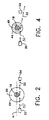
- the level may rise to the level of the beam or above, as shown in Figures 3 and 4, which is the level selected to represent a safe minimum operating diameter.
- the tubular extruded tube 44 and the internal bath 48 together provide a cylindrical lens.
- the lens causes the beam 32 (which is not normal to the extruded tube due to the offset position of the emitter) to refract as it passes through the inner bath liquid thereby, missing the sensor 34 ( Figures 3 and 4).
- the sensor no longer illuminated by the beam, signals the solenoid 36 to open valve 38 for admitting air into the extruded tube ( Figure 3).
- the introduction of air diametrically expands the extruded tube. This increases the volume of the clearance space 50 and the level of the internal bath 48 drops below the beam. When this happens, the beam again passes straight through the tube to illuminate the sensor.
- the illuminated sensor then signals the solenoid to close the air valve 38 and terminate the introduction of air.
- the refraction of the beam when the level of the internal bath reaches a given height provides an on/off indicator for introducing air into the extruded tube to restore the diameter of the extruded tube.
- the extruded tube can be kept larger than a diameter sufficient to avoid disruption of the extrusion process as would occur, for example, if the extruded tube came into contact with the stem of the mandrel.
- the adjustment is done independently of the pressure within the extruded tube.
- use of the apparatus as described provides a non invasive method for altering the tube diameter in that there is no physical contact made with the extruded tube itself.
- the present invention accomplished its intended objects in providing a method and apparatus for maintaining a clear, extruded tube of non derivatized cellulose at a desired diameter by adjusting the internal volume of the extruded tube to prevent excessive necking and making such adjustments in internal volume responsive to a change in the level of a pool of clear liquid maintained within the extruded tube.
- a second laser and sensor can be positioned at a lower level and arranged to bleed air from within the extruded tube should the diameter of the extruded tube increase beyond a desired maximum.
Landscapes
- Engineering & Computer Science (AREA)
- Life Sciences & Earth Sciences (AREA)
- Wood Science & Technology (AREA)
- Zoology (AREA)
- Food Science & Technology (AREA)
- Mechanical Engineering (AREA)
- Extrusion Moulding Of Plastics Or The Like (AREA)
- Measurement Of Levels Of Liquids Or Fluent Solid Materials (AREA)
Applications Claiming Priority (2)
| Application Number | Priority Date | Filing Date | Title |
|---|---|---|---|
| US296288 | 1999-04-22 | ||
| US09/296,288 US6264874B1 (en) | 1999-04-22 | 1999-04-22 | Method of controlling the diameter of a clear extruded tube |
Publications (2)
| Publication Number | Publication Date |
|---|---|
| EP1046340A1 true EP1046340A1 (fr) | 2000-10-25 |
| EP1046340B1 EP1046340B1 (fr) | 2004-03-10 |
Family
ID=23141390
Family Applications (1)
| Application Number | Title | Priority Date | Filing Date |
|---|---|---|---|
| EP99310583A Expired - Lifetime EP1046340B1 (fr) | 1999-04-22 | 1999-12-24 | Procédé et appareil de contrôle du diamètre de tuyaux extrudés transparents |
Country Status (6)
| Country | Link |
|---|---|
| US (1) | US6264874B1 (fr) |
| EP (1) | EP1046340B1 (fr) |
| AT (1) | ATE261249T1 (fr) |
| CA (1) | CA2282927C (fr) |
| DE (1) | DE69915451T2 (fr) |
| ES (1) | ES2217702T3 (fr) |
Families Citing this family (4)
| Publication number | Priority date | Publication date | Assignee | Title |
|---|---|---|---|---|
| US6547999B1 (en) * | 1999-10-18 | 2003-04-15 | Viskase Corporation | Cellulose food casing, cellulose composition and production method therefor |
| US6565796B1 (en) * | 2001-10-04 | 2003-05-20 | Viskase Corporation | Method and apparatus for use in manufacture of cellulose casing |
| GB0421199D0 (en) * | 2004-09-24 | 2004-10-27 | Emtelle Uk Ltd | Method of manufacturing a tube |
| CN104413133B (zh) * | 2013-09-04 | 2016-08-17 | 史宏志 | 一种用于制作超大口径干肠衣的模具 |
Citations (7)
| Publication number | Priority date | Publication date | Assignee | Title |
|---|---|---|---|---|
| EP0008781A1 (fr) * | 1978-09-01 | 1980-03-19 | Kollross, Günter | Mandrin extansible de plissage longitudinal de tuyaux flexibles, en particulier des boyaux artificiels pour la fabrication de saucisses |
| US4335488A (en) * | 1980-08-25 | 1982-06-22 | Hoechst Aktiengesellschaft | Device for filling a shirred tubular casing |
| US5277857A (en) | 1992-01-17 | 1994-01-11 | Viskase Corporation | Method of making a cellulose food casing |
| US5451364A (en) | 1992-01-17 | 1995-09-19 | Viskase Corporation | Cellulose food casing manufacturing method |
| US5759478A (en) | 1997-03-27 | 1998-06-02 | Viskase Corporation | Mandrel structure for use in manufacture of cellulose food casing |
| US5766540A (en) | 1997-03-27 | 1998-06-16 | Viskase Corporation | Cellulose food casing manufacturing method |
| EP0899076A1 (fr) * | 1997-08-27 | 1999-03-03 | Kalle Nalo GmbH & Co. KG | Procédé et dispositif pour la fabrication d'un produit tubulaire par extrusion à base de cellulose et sans soudure |
Family Cites Families (5)
| Publication number | Priority date | Publication date | Assignee | Title |
|---|---|---|---|---|
| US5352393A (en) * | 1990-03-21 | 1994-10-04 | Joseph Daniel R | Method of and apparatus for gaging and controlling circumference of extrusion-blown film |
| TW295607B (fr) * | 1993-05-24 | 1997-01-11 | Courtaulds Fibres Holdings Ltd | |
| US5354524A (en) * | 1993-05-24 | 1994-10-11 | Alan Sellars | Monitoring concentration of dope in product manufacture |
| MX9304245A (es) * | 1993-07-14 | 1995-01-31 | Celanese Mexicana Sa | Proceso continuo mejorado para la manufactura de envolturas tubulares paraalimentos. |
| US5658525A (en) * | 1995-08-04 | 1997-08-19 | Viskase Corporation | Cellulose food casing manufacturing method |
-
1999
- 1999-04-22 US US09/296,288 patent/US6264874B1/en not_active Expired - Fee Related
- 1999-09-21 CA CA002282927A patent/CA2282927C/fr not_active Expired - Fee Related
- 1999-12-24 ES ES99310583T patent/ES2217702T3/es not_active Expired - Lifetime
- 1999-12-24 DE DE69915451T patent/DE69915451T2/de not_active Expired - Fee Related
- 1999-12-24 AT AT99310583T patent/ATE261249T1/de not_active IP Right Cessation
- 1999-12-24 EP EP99310583A patent/EP1046340B1/fr not_active Expired - Lifetime
Patent Citations (7)
| Publication number | Priority date | Publication date | Assignee | Title |
|---|---|---|---|---|
| EP0008781A1 (fr) * | 1978-09-01 | 1980-03-19 | Kollross, Günter | Mandrin extansible de plissage longitudinal de tuyaux flexibles, en particulier des boyaux artificiels pour la fabrication de saucisses |
| US4335488A (en) * | 1980-08-25 | 1982-06-22 | Hoechst Aktiengesellschaft | Device for filling a shirred tubular casing |
| US5277857A (en) | 1992-01-17 | 1994-01-11 | Viskase Corporation | Method of making a cellulose food casing |
| US5451364A (en) | 1992-01-17 | 1995-09-19 | Viskase Corporation | Cellulose food casing manufacturing method |
| US5759478A (en) | 1997-03-27 | 1998-06-02 | Viskase Corporation | Mandrel structure for use in manufacture of cellulose food casing |
| US5766540A (en) | 1997-03-27 | 1998-06-16 | Viskase Corporation | Cellulose food casing manufacturing method |
| EP0899076A1 (fr) * | 1997-08-27 | 1999-03-03 | Kalle Nalo GmbH & Co. KG | Procédé et dispositif pour la fabrication d'un produit tubulaire par extrusion à base de cellulose et sans soudure |
Also Published As
| Publication number | Publication date |
|---|---|
| US6264874B1 (en) | 2001-07-24 |
| EP1046340B1 (fr) | 2004-03-10 |
| DE69915451T2 (de) | 2005-01-20 |
| ATE261249T1 (de) | 2004-03-15 |
| DE69915451D1 (de) | 2004-04-15 |
| ES2217702T3 (es) | 2004-11-01 |
| CA2282927A1 (fr) | 2000-10-22 |
| CA2282927C (fr) | 2004-11-30 |
Similar Documents
| Publication | Publication Date | Title |
|---|---|---|
| CA2096143C (fr) | Boyaux de cellulose, methode et appareil connexes | |
| EP1046340B1 (fr) | Procédé et appareil de contrôle du diamètre de tuyaux extrudés transparents | |
| US20010023000A1 (en) | Cellulose-based foodstuff casings prepared by the amine oxide process | |
| EP1301083B1 (fr) | Procede et dispositif de commande d'une machine a fabriquer des saucisses | |
| JP4361013B2 (ja) | 天然のケーシングにソーセージエマルジョンを詰め込むための方法および装置 | |
| JP2895471B2 (ja) | セルロース製の食品ケースの製造に使用するためのマンドレル構造 | |
| EP0867120A1 (fr) | Fabrication d'enveloppes pour aliments à base de cellulose | |
| RU2125804C1 (ru) | Непрерывный способ получения регенерированной целлюлозной трубчатой оболочки и оболочка, полученная этим способом | |
| US6444161B1 (en) | Mandrel structure for use in manufacture of cellulose food casing | |
| US2804642A (en) | Method and apparatus for the continuous expansion of tubular objects | |
| US2789315A (en) | Wet spinning apparatus | |
| KR100879408B1 (ko) | 소시지 에멀전에 의한 천연 케이싱 충진 방법 및 장치 | |
| WO2000023250A1 (fr) | Procede de fabrication de films | |
| US20040146668A1 (en) | Seamless tubular film, process and apparatus for producing a seamless tubular film | |
| JPS58500004A (ja) | 薄壁の可塑剤含有量の低い再生セルロ−ス製ソ−セ−ジケ−シング | |
| US4020534A (en) | Apparatus for monitoring stems of electrical light sources during manufacture | |
| MXPA98002395A (en) | Structure of mandril for use in the manufacture of cellulose wrapping for alime | |
| JP3688617B2 (ja) | セルロースケースの製造に使用するための方法及び装置 | |
| SU1705427A1 (ru) | Устройство дл пр дени искусственной оболочки | |
| JP2568156C (fr) |
Legal Events
| Date | Code | Title | Description |
|---|---|---|---|
| PUAI | Public reference made under article 153(3) epc to a published international application that has entered the european phase |
Free format text: ORIGINAL CODE: 0009012 |
|
| AK | Designated contracting states |
Kind code of ref document: A1 Designated state(s): AT BE DE ES FR GB |
|
| AX | Request for extension of the european patent |
Free format text: AL;LT;LV;MK;RO;SI |
|
| 17P | Request for examination filed |
Effective date: 20010425 |
|
| AKX | Designation fees paid |
Free format text: AT BE DE ES FR GB |
|
| REG | Reference to a national code |
Ref country code: GB Ref legal event code: FG4D |
|
| GRAP | Despatch of communication of intention to grant a patent |
Free format text: ORIGINAL CODE: EPIDOSNIGR1 |
|
| GRAS | Grant fee paid |
Free format text: ORIGINAL CODE: EPIDOSNIGR3 |
|
| GRAA | (expected) grant |
Free format text: ORIGINAL CODE: 0009210 |
|
| RAP1 | Party data changed (applicant data changed or rights of an application transferred) |
Owner name: VISKASE CORPORATION |
|
| RIN1 | Information on inventor provided before grant (corrected) |
Inventor name: NIELSEN, NIEL EDWIN |
|
| AK | Designated contracting states |
Kind code of ref document: B1 Designated state(s): AT BE DE ES FR GB |
|
| REF | Corresponds to: |
Ref document number: 69915451 Country of ref document: DE Date of ref document: 20040415 Kind code of ref document: P |
|
| REG | Reference to a national code |
Ref country code: ES Ref legal event code: FG2A Ref document number: 2217702 Country of ref document: ES Kind code of ref document: T3 |
|
| ET | Fr: translation filed | ||
| PLBE | No opposition filed within time limit |
Free format text: ORIGINAL CODE: 0009261 |
|
| STAA | Information on the status of an ep patent application or granted ep patent |
Free format text: STATUS: NO OPPOSITION FILED WITHIN TIME LIMIT |
|
| 26N | No opposition filed |
Effective date: 20041213 |
|
| PGFP | Annual fee paid to national office [announced via postgrant information from national office to epo] |
Ref country code: AT Payment date: 20061204 Year of fee payment: 8 |
|
| PGFP | Annual fee paid to national office [announced via postgrant information from national office to epo] |
Ref country code: GB Payment date: 20061222 Year of fee payment: 8 |
|
| PGFP | Annual fee paid to national office [announced via postgrant information from national office to epo] |
Ref country code: ES Payment date: 20071226 Year of fee payment: 9 |
|
| PGFP | Annual fee paid to national office [announced via postgrant information from national office to epo] |
Ref country code: DE Payment date: 20080131 Year of fee payment: 9 |
|
| PGFP | Annual fee paid to national office [announced via postgrant information from national office to epo] |
Ref country code: FR Payment date: 20071217 Year of fee payment: 9 |
|
| GBPC | Gb: european patent ceased through non-payment of renewal fee |
Effective date: 20071224 |
|
| PG25 | Lapsed in a contracting state [announced via postgrant information from national office to epo] |
Ref country code: AT Free format text: LAPSE BECAUSE OF NON-PAYMENT OF DUE FEES Effective date: 20071224 |
|
| PGFP | Annual fee paid to national office [announced via postgrant information from national office to epo] |
Ref country code: BE Payment date: 20071231 Year of fee payment: 9 |
|
| PG25 | Lapsed in a contracting state [announced via postgrant information from national office to epo] |
Ref country code: GB Free format text: LAPSE BECAUSE OF NON-PAYMENT OF DUE FEES Effective date: 20071224 |
|
| BERE | Be: lapsed |
Owner name: *VISKASE CORP. Effective date: 20081231 |
|
| PG25 | Lapsed in a contracting state [announced via postgrant information from national office to epo] |
Ref country code: BE Free format text: LAPSE BECAUSE OF NON-PAYMENT OF DUE FEES Effective date: 20081231 |
|
| REG | Reference to a national code |
Ref country code: FR Ref legal event code: ST Effective date: 20090831 |
|
| PG25 | Lapsed in a contracting state [announced via postgrant information from national office to epo] |
Ref country code: DE Free format text: LAPSE BECAUSE OF NON-PAYMENT OF DUE FEES Effective date: 20090701 |
|
| REG | Reference to a national code |
Ref country code: ES Ref legal event code: FD2A Effective date: 20081226 |
|
| PG25 | Lapsed in a contracting state [announced via postgrant information from national office to epo] |
Ref country code: FR Free format text: LAPSE BECAUSE OF NON-PAYMENT OF DUE FEES Effective date: 20081231 Ref country code: ES Free format text: LAPSE BECAUSE OF NON-PAYMENT OF DUE FEES Effective date: 20081226 |