EP1046357A1 - Appareil de vaporisation - Google Patents
Appareil de vaporisation Download PDFInfo
- Publication number
- EP1046357A1 EP1046357A1 EP00420077A EP00420077A EP1046357A1 EP 1046357 A1 EP1046357 A1 EP 1046357A1 EP 00420077 A EP00420077 A EP 00420077A EP 00420077 A EP00420077 A EP 00420077A EP 1046357 A1 EP1046357 A1 EP 1046357A1
- Authority
- EP
- European Patent Office
- Prior art keywords
- base
- tank
- vaporization
- pump
- spray
- Prior art date
- Legal status (The legal status is an assumption and is not a legal conclusion. Google has not performed a legal analysis and makes no representation as to the accuracy of the status listed.)
- Granted
Links
- 239000006200 vaporizer Substances 0.000 title 1
- 230000008016 vaporization Effects 0.000 claims abstract description 44
- 238000009834 vaporization Methods 0.000 claims abstract description 44
- 239000002304 perfume Substances 0.000 claims description 28
- 239000007921 spray Substances 0.000 claims description 27
- 239000012530 fluid Substances 0.000 claims description 20
- 238000005507 spraying Methods 0.000 claims description 17
- 239000007788 liquid Substances 0.000 claims description 14
- 238000005086 pumping Methods 0.000 claims description 10
- 230000006835 compression Effects 0.000 claims description 7
- 238000007906 compression Methods 0.000 claims description 7
- 230000006837 decompression Effects 0.000 claims description 5
- 230000005484 gravity Effects 0.000 claims description 5
- 230000000903 blocking effect Effects 0.000 claims description 3
- 230000000284 resting effect Effects 0.000 claims description 2
- 239000000725 suspension Substances 0.000 claims description 2
- 239000007789 gas Substances 0.000 description 4
- 210000003811 finger Anatomy 0.000 description 3
- 235000014443 Pyrus communis Nutrition 0.000 description 2
- 230000008447 perception Effects 0.000 description 2
- 238000007789 sealing Methods 0.000 description 2
- 210000003813 thumb Anatomy 0.000 description 2
- 241001310793 Podium Species 0.000 description 1
- 230000001133 acceleration Effects 0.000 description 1
- 239000000443 aerosol Substances 0.000 description 1
- 230000000295 complement effect Effects 0.000 description 1
- 238000002788 crimping Methods 0.000 description 1
- 230000000694 effects Effects 0.000 description 1
- 230000007613 environmental effect Effects 0.000 description 1
- 230000006870 function Effects 0.000 description 1
- 239000011521 glass Substances 0.000 description 1
- 239000000463 material Substances 0.000 description 1
- 239000007769 metal material Substances 0.000 description 1
- 210000000056 organ Anatomy 0.000 description 1
- 238000005192 partition Methods 0.000 description 1
- 230000016776 visual perception Effects 0.000 description 1
- 210000000707 wrist Anatomy 0.000 description 1
Images

Classifications
-
- A—HUMAN NECESSITIES
- A45—HAND OR TRAVELLING ARTICLES
- A45D—HAIRDRESSING OR SHAVING EQUIPMENT; EQUIPMENT FOR COSMETICS OR COSMETIC TREATMENTS, e.g. FOR MANICURING OR PEDICURING
- A45D34/00—Containers or accessories specially adapted for handling liquid toiletry or cosmetic substances, e.g. perfumes
- A45D34/02—Scent flasks, e.g. with evaporator
-
- B—PERFORMING OPERATIONS; TRANSPORTING
- B05—SPRAYING OR ATOMISING IN GENERAL; APPLYING FLUENT MATERIALS TO SURFACES, IN GENERAL
- B05B—SPRAYING APPARATUS; ATOMISING APPARATUS; NOZZLES
- B05B11/00—Single-unit hand-held apparatus in which flow of contents is produced by the muscular force of the operator at the moment of use
- B05B11/0005—Components or details
- B05B11/0059—Components or details allowing operation in any orientation, e.g. for discharge in inverted position
Definitions
- the present invention relates to the technical field of spray capable of being gripped and handled by hand by a user view to ensure, by action on a manual control member, the vaporization of the liquid or fluid contained in the tank, and for example of a perfume.
- the present invention relates to a vaporization device capable of being gripped and handled by hand, comprising a reservoir of liquid to be vaporized and a vaporization system comprising a vaporization orifice, a means of pumping and a manual spray control member.
- Perfume dispensers therefore have a new times evolved by implementing, as in all devices previously described, a bottle provided with an opening in its part upper, opening in which a vaporization system has been mounted comprising a spray orifice, a pumping means and a member manual spray control.
- the means pumping is a conventional type pump operating by compression / depression using an elastic mounting under the effect of pressure exerted by the manual control member, the pump being connected liquid through a dip tube extending over the entire height of the reservoir bottle.
- the spraying gesture is therefore carried out in normal operation with the spray system located above the perfume tank, the user manipulating the bottle with one hand and pressing the manual control member by pressing with the index finger. Each press of the index finger vaporizes a dose of perfume, release of the manual control member generating the ascent and simultaneously replacing the volume of liquid vaporized by a equivalent volume of air through the pump body.
- Vaporizers designed according to this principle give generally satisfactory, are easily transportable due to the good sealing of their design and are able to provide comfort of use generally appreciated by the user.
- Such devices suffer from various disadvantages.
- the presence of a spray system at the top of the bottle imposes a series of technical constraints and in particular the existence of a push button in the upper part of the bottle imposing a system of closing at this location.
- the presence of closure system limits the design possibilities of the bottle.
- the presence of a dip tube in the bottle represents, on the plan aesthetic, an element unfavorable to the general perception of the spraying, except for making an opaque spraying device.
- the general presentation possibilities of the vaping are also limited to presentation modes without direct visual perception of the liquid, which may also prove to be a factor negatively perceived by the potential buyer.
- the existence of a dip tube usually involves difficult emptying of the entire volume of liquid when a minimal amount of liquid remains the end of the dip tube.
- the invention therefore aims to remedy the various disadvantages listed above, and to propose a new spray capable of being gripped and handled by hand, of new design and improved configuration.
- Another object assigned to the invention aims to propose a new apparatus for vaporization likely to lead to new possibilities of particularly attractive presentation.
- Another object of the invention is to propose a new apparatus for vaporization of particularly simple design and operation waterproof.
- Another object of the invention is to propose a new apparatus for spraying whose grip, handling and use are particularly ergonomic.
- Another object of the invention is to provide a new vaporization device whose operation is particularly safe and reliable.
- a complementary object of the invention aims to propose a new device spray particularly suitable for spraying perfume.
- a spray capable of being gripped and handled by hand, comprising a reservoir of fluid to be vaporized and a vaporization system comprising a orifice vaporization, pumping means and a manual control member vaporization, characterized in that the reservoir is associated towards its lower part of a base, the vaporization system being integrated in the base and designed to allow, in the normal position to operation, vaporization of the fluid with the vaporization system located under the tank.
- a spraying device capable of being grasped and handled by hand, consisting of a perfume sprayer, it being understood that the spraying device according to the invention cannot in no way be limited to this type of application.
- the vaporization device according to the invention could be used in other applications, as soon as it is a question of ensuring the vaporization of any fluid, in particular a liquid, by gripping and proper handling of the device.
- vaporization apparatus any vaporization apparatus capable of being grasped and manipulated by hand and capable of vaporizing a fluid, which it it is a perfume sprayer or a sprayer usable in close fields, such as cosmetology, even the medical field in particular.
- the spraying apparatus is in the form of a unit able to be entered at / or, in the hand (s) and to be handled preferably with one hand.
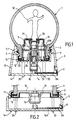
- he comprises a reservoir 1 of fluid, in particular of liquid, and in particular intended to ensure the storage of a perfume.
- the shape of the fluid reservoir 1 may be arbitrary, it being understood that in the examples given for illustrative purposes only, one form for example of the reservoir will substantially spherical at its upper part, said fluid reservoir 1 is ending at its lower part with an open neck 2, of section for example circular.
- the fluid reservoir 1 can be produced either in one plastic or glass material, and be translucent, transparent or opaque rays of light, in whole or in part.
- the fluid reservoir 1 is associated towards its lower part to a base 3 in which a vaporization system 4 is integrated and mounted permanently.
- the base 3 is advantageously formed of a separate part from the reservoir 1, said base 3 being mounted integral with the tank 1 and fixed under the latter, removable or not.
- the mounting of the tank 1 on the base 3 can be produced by cooperation between one or several flanges 5 forming a thread projecting radially from of the neck 2, with a thread 6 formed in the upper part of the base 3.
- Other mounting systems can be envisaged, such as a respective fitting of the reservoir 1 and the base 3.
- the fluid reservoir 1 is mounted above the base 3 in the inverted position, that is to say that the tank 1 discharge opening, defined by the outer limits of the neck 2, is directed downwards and towards the base 3.
- the upper part of the tank 1 is devoid of any accessory, since the tank 1 is mounted with its opening reverse evacuation.
- the reservoir 1 has a lower opening limited by the neck 2, said lower opening being closed in a sealed manner by a floor 10 attached and fixed to the tank 1 and serving as an interface, connection and connection with the vaporization system 4 via a calibrated orifice 9 made in its thickness in order to ensure the passage fluid by gravity.
- the floor 10 is attached to the neck 2 by crimping an annular ring 11, a seal annular 12 being interposed between said ring and the lower end of the neck 2.
- the base 3 made for example of metallic material or plastic, has a main body forming a lateral envelope 13 and a bottom 14 including at least a substantially flat part to form a stable rest base intended to rest on a flat surface.
- the spray apparatus according to the invention is advantageously suitable for occupying a stable presentation position on a display stand incorporating a push-button function mounted in the back 14.
- the vaporization system 4 incorporated and arranged in the internal volume defined by the base 3, conventionally comprises an orifice vaporization 8 integral with the wall 13 and by which the liquid will be vaporized outwards, a pumping means 15 connected by a channel 8A to the orifice of vaporization 8 and a manual control member 16 of the vaporization intended to be actuated by the user to ensure the expulsion of the fluid.
- the vaporization system 4 according to the invention, and particular the pumping means, is designed, chosen and arranged in the base 3 so as to allow, in normal operating position such as illustrated in Figures 1, 2 and 3, the vaporization of the fluid with the vaporization 4 located under the tank 1, preferably directly above it latest.
- the pumping means namely the pump 15, is formed by an inverted pump, fed by simple gravity from the tank 1 so as to present its inlet / compression chamber and its vaporization head 8 arranged downwards under the tank 1 for draw the fluid in the pump body without risk of leakage during entry renewal air through the spray port 8.
- the pump 15 used is a return air pump due to the use of a fluid reservoir 1 of the rigid type.
- a fluid reservoir 1 of the rigid type it is possible to envisage the use of so-called " air less" pumps , without air return, in the event of the use of a fluid reservoir 1 capable of deforming to withstand the variation in internal pressure.
- the pumps which can be used in the type of geometrical position desired, namely in the inverted upside down position, may be pumps which can be commonly found in commerce, such as those called “all positions " manufactured by the company EMSON (brand registered), or for example by the company PFEIFFER (registered trademark), as soon as they authorize operation in a substantially inverted position.
- the reverse pump 15 is mounted in the base 3, under the reservoir 1 and in direct or indirect relation with the orifice 9, by via a valve 20 mounted elastically mobile via a sealed reception seat against and on said orifice 9.
- a valve 20 mounted elastically mobile via a sealed reception seat against and on said orifice 9.
- the inverted pump 15 when the base 3 is not formed from a separate part of the tank 1, but on the contrary forms by extension the lower part of said tank, the inverted pump 15 will then be mounted in this lower part of the reservoir 1 forming the base.
- the reverse pump 15 is mounted in the base 3 or at the bottom of tank 1, with its corresponding compression / decompression axis to its axis of axial symmetry, oriented substantially vertically in consideration of the normal operating position of the device which is itself substantially vertical.
- Pump 15 can be mounted and fixed in a housing 21 coming directly from the floor 10 ( Figure 2) or at otherwise be mounted in an intermediate housing 22 fixed on a partition upper 23 ( Figure 1) of the base 3, the lower part of the pump 15 resting on the bottom 14 of the base 3.
- the sealing of the assembly between the neck 2 and the base 3 is ensured by the interposition of one or more annular seals 24, interposed by example between the housing 22 and the floor 10.
- the manual control member 16 of the spraying is mounted on the base 3.
- the manual control member 16 can be integrated in the bottom 14, in the form of a push button axially actuable by the user, and movable along the axis of axial symmetry of the pump 15.
- the manual control member 16 is formed by a pusher plate 16A forming the very bottom of the base 3, said plate being mounted mobile, with the possibility of axial sliding relative to the body of the base 3 and functionally connected to the pump 15.
- the whole of the lower part of the base 3 is therefore likely to move and slide relative to the rest of the base 3 or relative to the whole of the lower part of the tank 1.
- the body of the base is provided with at least one member support 30 on which (which) the device rests.
- the support member 30 is formed by a set of feet, integral of the base 3 and fixedly mounted relative to the latter, said feet passing through openings made through the plate push button 16A. Thanks to this arrangement, the vaporizing device conforms to the invention can rest freely on a substantially flat support, without risk of accidentally actuating the push-button plate 16A susceptible to trigger the spraying of a dose of product.
- the spray device according to the invention is advantageously completed by the mounting of a base 31 fixed directly or indirectly on the floor 10, to rest on the latter.
- the base 31 is thus susceptible to form a support for mounting one (or more) organ (s) decorative (s) 32 extending in the reservoir 1.
- the member decorative 31 can be made in the form of a fixed figurine, for example by means of studs or lugs, directly on the floor 10.
- FIG. 3 illustrates an alternative embodiment according to the invention but does not differing from the variant shown in FIG. 1 only by a different mounting from the pump 15.
- the pump 15 is mounted in the base 3, under tank 1, with its oriented compression / decompression axis substantially perpendicular to the normal operating position of the apparatus, the axis of axial symmetry of the pump 15 therefore extending substantially horizontally.
- the member manual control valve 16C is then arranged laterally in the walls 13 of the base 3 so that it can be actuated according to the very axis of operation of the pump 15. Apart from this difference in positioning of the pump 15, all the other characteristics of mounting of the spray device are identical.
- the vaporizing apparatus can be provided with a blocking / unblocking means 35 ( Figures 4 and 5) of the manual control member 16 for spraying.
- a blocking / unblocking means 35 ( Figures 4 and 5) of the manual control member 16 for spraying.
- a means is formed by a lever 36 mounted articulated between two stop positions on the bottom 14 or 16A of the base 3.
- the lever 36 In a stop position shown in solid lines in FIG. 4, the lever 36 is in inactive position, i.e. unlocking of the control member manual 16 spray.
- the head 38 of the lever engages between the push plate 16A and the lower part of the pump 15 so as to block any relative movement of the push plate 16A relative to the device. This avoids any unexpected actuation of the manual control 16 of spraying.
- the lever is advantageously mounted inside the base 3, directly on the internal face of the push plate 16A.
- the end 36A lever 36 is curved and passes through a slot 40 formed in the push plate 16A so that it can be directly accessed by the user.
- the apparatus When the user wishes to use the spray device in accordance with the invention, he grasped, generally with one hand, the apparatus, either by passing the thumb under base 3, the other fingers being applied to the part tank 1, either by reversing such a position, the thumb being then applied to the upper part of the tank 1.
- the means of blocking / unblocking 35 being in its inactive position, the user can then ensure the emission of a dose of perfume by simply compressing either the push plate 16A, i.e. the side push button 16C.
- the invention therefore makes it possible to produce a vaporization apparatus of a new design leading to possibilities of layout and news configuration.
- the clearance of the entire upper part of the tank 1 ensures a particularly attractive and new presentation of the vaporizing apparatus according to the invention, since all the part upper part of the appliance is free and free.
- the spray device according to the invention also allows a multiplicity seizure and manipulation positions favoring movement clean of seizure and manipulation by authorizing in particular a more great freedom of orientation of the wrist.
- the reservoir 1 may include a plurality of glitter in free suspension in the liquid to be vaporized in order to constitute an additional decorative element.
- the spray apparatus according to the invention will include advantageously a filter 40A (FIG. 1), for example annular, mounted between floor 10 and podium 31, intended to protect pump 15 by avoiding the introduction of foreign bodies.
- filters 40A for example annular, mounted between floor 10 and podium 31, intended to protect pump 15 by avoiding the introduction of foreign bodies.
- Other locations and 40A filter configurations are obviously possible.
- the tank 1 can also be removably mounted on the base 3, to form a rechargeable device.
Landscapes
- Containers And Packaging Bodies Having A Special Means To Remove Contents (AREA)
- Vaporization, Distillation, Condensation, Sublimation, And Cold Traps (AREA)
- Filling Or Discharging Of Gas Storage Vessels (AREA)
- Organic Low-Molecular-Weight Compounds And Preparation Thereof (AREA)
Abstract
Description
- la figure 1 montre, selon une vue en coupe transversale longitudinale, une première variante de réalisation d'un appareil de vaporisation conforme à l'invention.
- la figure 2 montre, selon une vue en coupe transversale longitudinale partielle, un détail de réalisation d'une embase selon l'invention montée sur un appareil de vaporisation conforme à l'invention.
- la figure 3 montre, selon une vue en coupe transversale longitudinale, une variante de réalisation d'un appareil de vaporisation conforme à l'invention.
- la figure 4 montre, selon une vue de dessous, un détail de réalisation d'un organe de blocage monté dans l'embase d'un appareil de vaporisation conforme à l'invention.
- la figure 5 montre, selon une vue en coupe transversale partielle, un détail de réalisation d'un organe de blocage conforme à l'invention.
Claims (15)
- Appareil de vaporisation apte à être saisi et manipulé à la main, comportant un réservoir de fluide (1) à vaporiser et un système de vaporisation (4) comprenant un orifice de vaporisation (8), un moyen de pompage (15) et un organe de commande manuelle (16, 16C) de la vaporisation, caractérisé en ce que le réservoir (1) est associé vers sa partie inférieure à une embase (3), le système de vaporisation (4) étant intégré dans l'embase (3) et conçu de manière à permettre, en position normale de fonctionnement, la vaporisation du fluide avec le système de vaporisation (4) situé sous le réservoir (1).
- Appareil selon la revendication 1 caractérisé en ce que l'embase (3) est formée d'une pièce distincte du réservoir (1) qui est montée solidaire du réservoir (1) et fixée sous celui-ci, de manière amovible ou non.
- Appareil selon l'une des revendications 1 ou 2 caractérisé en ce que l'embase (3) comporte un fond (14) avec une partie sensiblement plane pour former une embase (3) de repos stable.
- Appareil selon l'une des revendications 1 à 3 caractérisé en ce que le moyen de pompage (15) est formé par une pompe inversée, alimentée par gravité à partir du réservoir(1).
- Appareil selon la revendication 4 caractérisé en ce que la pompe inversée (15) est montée dans l'embase (3) sous le réservoir (1), ou à la partie inférieure du réservoir (1 ), avec son axe de compression/décompression orienté sensiblement verticalement en considération de la position normale de fonctionnement de l'appareil.
- Appareil selon l'une des revendications 1 et 5 caractérisé en ce que l'organe de commande manuelle (16, 16C) est monté sur l'embase (3).
- Appareil selon la revendication 6 caractérisé en ce que l'organe de commande manuelle (16) est formé par une plaque poussoir (16A) formant le fond (14) de l'embase (3), ladite plaque étant montée mobile, avec possibilité de coulissement axial, relativement au corps de l'embase (3).
- Appareil selon la revendication 7 caractérisé en ce que le corps de l'embase (3) est pourvu d'au moins un organe support (30) sur lequel (lesquels) repose l'appareil.
- Appareil selon l'une des revendications 1 à 4 caractérisé en ce que la pompe inversée (15) est montée dans l'embase (3), sous le réservoir (1), avec son axe de compression/décompression orienté sensiblement perpendiculairement à la position normale de fonctionnement de l'appareil, l'organe de commande manuelle (16C) de vaporisation étant disposé latéralement dans les parois (13) de l'embase (3).
- Appareil selon l'une des revendications 1 à 9 caractérisé en ce que le réservoir (1) comporte une ouverture inférieure, fermée de manière étanche par un plancher (10) rapporté, servant d'interface de liaison et de connexion avec le moyen de pompage (15) par l'intermédiaire d'un orifice calibré (9).
- Appareil selon la revendication 10 caractérisé en ce qu'il comporte :un socle (31) monté dans le réservoir (1) et reposant sur le plancher (10),et un organe décoratif (32), de préférence une figurine, fixé sur le socle (31).
- Appareil selon l'une des revendications 1 à 11 caractérisé en ce qu'il comporte un moyen de blocage/déblocage (35) de l'organe de commande manuelle (16) de vaporisation.
- Appareil selon l'une des revendications 1 à 12 caractérisé en ce que la partie supérieure du réservoir est dépourvue d'accessoires.
- Appareil selon l'une des revendications 1 à 13 caractérisé en ce qu'il est constitué par un vaporisateur de parfum.
- Appareil selon la revendication 14 caractérisé en ce qu'il comporte une pluralité de paillettes en suspension libre dans le liquide à vaporiser.
Applications Claiming Priority (2)
| Application Number | Priority Date | Filing Date | Title |
|---|---|---|---|
| FR9905558A FR2792511B1 (fr) | 1999-04-23 | 1999-04-23 | Appareil de vaporisation a pompe inversee |
| FR9905558 | 1999-04-23 |
Publications (2)
| Publication Number | Publication Date |
|---|---|
| EP1046357A1 true EP1046357A1 (fr) | 2000-10-25 |
| EP1046357B1 EP1046357B1 (fr) | 2004-06-23 |
Family
ID=9545120
Family Applications (1)
| Application Number | Title | Priority Date | Filing Date |
|---|---|---|---|
| EP00420077A Expired - Lifetime EP1046357B1 (fr) | 1999-04-23 | 2000-04-18 | Appareil de vaporisation |
Country Status (7)
| Country | Link |
|---|---|
| US (1) | US6592006B1 (fr) |
| EP (1) | EP1046357B1 (fr) |
| JP (1) | JP4790893B2 (fr) |
| AT (1) | ATE269647T1 (fr) |
| DE (1) | DE60011698T2 (fr) |
| ES (1) | ES2223429T3 (fr) |
| FR (1) | FR2792511B1 (fr) |
Cited By (1)
| Publication number | Priority date | Publication date | Assignee | Title |
|---|---|---|---|---|
| CN105797889A (zh) * | 2016-02-03 | 2016-07-27 | 惠州三高电子科技有限公司 | 一种喷雾产品的喷气控制装置 |
Families Citing this family (2)
| Publication number | Priority date | Publication date | Assignee | Title |
|---|---|---|---|---|
| FR2916658A1 (fr) * | 2007-05-30 | 2008-12-05 | Lir France Soc Par Actions Sim | Vaporisateur sans tube plongeur |
| FR2941602B1 (fr) * | 2009-02-05 | 2011-03-11 | Oreal | Ensemble de conditionnement et de distribution d'un produit cosmetique |
Citations (5)
| Publication number | Priority date | Publication date | Assignee | Title |
|---|---|---|---|---|
| US3029001A (en) * | 1959-12-28 | 1962-04-10 | Matthew B Blish | Flexible dispensing closure for rigid containers |
| EP0173885A2 (fr) * | 1984-09-06 | 1986-03-12 | Erich Schumm KG | Distributeur de savon |
| US4662195A (en) * | 1983-08-08 | 1987-05-05 | United States Borax & Chemical Corporation | Wall-mounted soap dispenser |
| EP0444990A1 (fr) * | 1990-02-28 | 1991-09-04 | L'oreal | Dispositif distributeur de produit liquide ou pateux, notamment de produit cosmétique |
| US5476198A (en) * | 1993-05-26 | 1995-12-19 | Valois S.A. | Liquid dispenser device without a dip-tube |
Family Cites Families (15)
| Publication number | Priority date | Publication date | Assignee | Title |
|---|---|---|---|---|
| JPS51106646U (fr) * | 1975-02-25 | 1976-08-26 | ||
| JPS5684663A (en) * | 1979-12-11 | 1981-07-10 | Yoshino Kogyosho Co Ltd | Sprayer |
| US4424919A (en) * | 1981-10-28 | 1984-01-10 | Diamond International Corporation | Dispenser having plunger locking means |
| JPH0465154U (fr) * | 1990-10-09 | 1992-06-05 | ||
| US5489044A (en) * | 1991-05-20 | 1996-02-06 | Hygiene-Technik Inc. | Method of preparing replaceable liquid soap reservoir |
| JPH0534183U (ja) * | 1991-10-01 | 1993-05-07 | 幸立化成工業株式会社 | ジヤバラ式排出容器 |
| JP2563083Y2 (ja) * | 1992-02-07 | 1998-02-18 | 東洋製罐株式会社 | 吐出量可変ポンプ |
| US5261848A (en) * | 1992-12-31 | 1993-11-16 | Playskool, Inc. | Toy with liquid-filled shell |
| JPH0731662A (ja) * | 1993-07-16 | 1995-02-03 | Saraya Kk | 手指消毒器 |
| US5368205A (en) * | 1993-07-19 | 1994-11-29 | Banner Beverage Systems, Inc. | Apparatus for controlling foaming and flowrate in beverage dispensing systems |
| ATE187877T1 (de) * | 1995-03-29 | 2000-01-15 | Hagleitner Betriebshygiene | Seifenschaumspender |
| US5666750A (en) * | 1995-05-25 | 1997-09-16 | M.H. Segan Limited Partnership | Decorative article with flake circulating means |
| US6065640A (en) * | 1997-04-18 | 2000-05-23 | Ho; Stanley | Dispenser |
| US5887762A (en) * | 1997-08-06 | 1999-03-30 | Bobrick Washroom Equipment, Inc. | Replaceable valve system |
| US5989655A (en) * | 1998-04-06 | 1999-11-23 | Meng; Sally | Crystal ball ornament |
-
1999
- 1999-04-23 FR FR9905558A patent/FR2792511B1/fr not_active Expired - Lifetime
-
2000
- 2000-04-18 EP EP00420077A patent/EP1046357B1/fr not_active Expired - Lifetime
- 2000-04-18 DE DE60011698T patent/DE60011698T2/de not_active Expired - Lifetime
- 2000-04-18 AT AT00420077T patent/ATE269647T1/de active
- 2000-04-18 ES ES00420077T patent/ES2223429T3/es not_active Expired - Lifetime
- 2000-04-20 US US09/553,577 patent/US6592006B1/en not_active Expired - Fee Related
- 2000-04-24 JP JP2000127653A patent/JP4790893B2/ja not_active Expired - Lifetime
Patent Citations (5)
| Publication number | Priority date | Publication date | Assignee | Title |
|---|---|---|---|---|
| US3029001A (en) * | 1959-12-28 | 1962-04-10 | Matthew B Blish | Flexible dispensing closure for rigid containers |
| US4662195A (en) * | 1983-08-08 | 1987-05-05 | United States Borax & Chemical Corporation | Wall-mounted soap dispenser |
| EP0173885A2 (fr) * | 1984-09-06 | 1986-03-12 | Erich Schumm KG | Distributeur de savon |
| EP0444990A1 (fr) * | 1990-02-28 | 1991-09-04 | L'oreal | Dispositif distributeur de produit liquide ou pateux, notamment de produit cosmétique |
| US5476198A (en) * | 1993-05-26 | 1995-12-19 | Valois S.A. | Liquid dispenser device without a dip-tube |
Cited By (2)
| Publication number | Priority date | Publication date | Assignee | Title |
|---|---|---|---|---|
| CN105797889A (zh) * | 2016-02-03 | 2016-07-27 | 惠州三高电子科技有限公司 | 一种喷雾产品的喷气控制装置 |
| CN105797889B (zh) * | 2016-02-03 | 2017-12-05 | 惠州三高电子科技有限公司 | 一种喷雾产品的喷气控制装置 |
Also Published As
| Publication number | Publication date |
|---|---|
| DE60011698D1 (de) | 2004-07-29 |
| ES2223429T3 (es) | 2005-03-01 |
| JP2000350951A (ja) | 2000-12-19 |
| DE60011698T2 (de) | 2005-08-18 |
| FR2792511B1 (fr) | 2001-06-08 |
| HK1032343A1 (en) | 2001-07-20 |
| ATE269647T1 (de) | 2004-07-15 |
| EP1046357B1 (fr) | 2004-06-23 |
| JP4790893B2 (ja) | 2011-10-12 |
| US6592006B1 (en) | 2003-07-15 |
| FR2792511A1 (fr) | 2000-10-27 |
Similar Documents
| Publication | Publication Date | Title |
|---|---|---|
| EP1035038B9 (fr) | Ensemble pour le conditionnement et la distribution sous pression d'un produit, notamment cosmétique | |
| EP3310491B1 (fr) | Système et procédé de re-remplissage en liquide d'un flacon | |
| CA2152147C (fr) | Pompe manuelle a precompression pour la pulverisation d'un liquide et ensemble de distribution equipe d'une telle pompe | |
| EP2969241B1 (fr) | Dispositif rechargeable de conditionnement et de distribution d'un produit fluide | |
| EP2441344A1 (fr) | Procédé et flacon de distribution d'un produit fluide | |
| EP0945367A1 (fr) | Récipient distributeur d'un produit fluide comportant un flacon muni d'un organe de distributeur relié à un tube plongeur | |
| FR2524348A1 (fr) | Vaporisateur pompe | |
| EP2397422B1 (fr) | Système de distribution d'un produit fluide | |
| EP0988234B1 (fr) | Contenant muni d'un embout de distribution avec couvercle retractable | |
| CA2407213C (fr) | Dispositif de pulverisation d'au moins un produit sur un support, notamment un support keratinique tel que la peau | |
| CH421847A (fr) | Appareil pour la distribution fractionnée d'un produit liquide ou pulvérulent | |
| FR2949762A1 (fr) | Bouton poussoir pour un systeme de distribution d'un produit sous pression. | |
| EP1046357B1 (fr) | Appareil de vaporisation | |
| EP2457667B1 (fr) | Système de distribution d'un produit fluide | |
| EP0331561B1 (fr) | Dispositif pour permettre l'emploi en toutes positions d'une valve de vaporisateur | |
| FR2650763A1 (fr) | Vaporisateur portatif rechargeable pour liquides | |
| FR2966808A1 (fr) | Systeme et flacon de distribution d'un produit fluide | |
| WO1999034930A1 (fr) | Atomiseur rechargeable | |
| EP2904929A1 (fr) | Système de distribution d'un produit fluide conditionné dans un flacon | |
| WO2014147351A1 (fr) | Distributeur de produit fluide rechargeable | |
| FR2668082A1 (fr) | Dispositif de distribution ou de pulverisation sans reprise d'air d'un produit fluide, et son procede de montage. | |
| EP4395602A1 (fr) | Bouton-poussoir pour testeur à pompe, et testeur à pompe équipé d'un tel bouton-poussoir | |
| FR3034293A1 (fr) | Coque amovible pour vaporisateur rechargeable portatif | |
| FR2607785A1 (fr) | Capuchon distributeur a partie mobile externe, recipient comportant un tel capuchon, et procede d'assemblage du capuchon au recipient | |
| EP4064927B1 (fr) | Dispositif de distribution de produit liquide ou pâteux |
Legal Events
| Date | Code | Title | Description |
|---|---|---|---|
| PUAI | Public reference made under article 153(3) epc to a published international application that has entered the european phase |
Free format text: ORIGINAL CODE: 0009012 |
|
| AK | Designated contracting states |
Kind code of ref document: A1 Designated state(s): AT BE CH CY DE DK ES FI FR GB GR IE IT LI LU MC NL PT SE |
|
| AX | Request for extension of the european patent |
Free format text: AL;LT;LV;MK;RO;SI |
|
| 17P | Request for examination filed |
Effective date: 20010406 |
|
| AKX | Designation fees paid |
Free format text: AT BE CH CY DE DK ES FI FR GB GR IE IT LI LU MC NL PT SE |
|
| 17Q | First examination report despatched |
Effective date: 20030109 |
|
| GRAP | Despatch of communication of intention to grant a patent |
Free format text: ORIGINAL CODE: EPIDOSNIGR1 |
|
| GRAS | Grant fee paid |
Free format text: ORIGINAL CODE: EPIDOSNIGR3 |
|
| GRAA | (expected) grant |
Free format text: ORIGINAL CODE: 0009210 |
|
| AK | Designated contracting states |
Kind code of ref document: B1 Designated state(s): AT BE CH CY DE DK ES FI FR GB GR IE IT LI LU MC NL PT SE |
|
| PG25 | Lapsed in a contracting state [announced via postgrant information from national office to epo] |
Ref country code: NL Free format text: LAPSE BECAUSE OF FAILURE TO SUBMIT A TRANSLATION OF THE DESCRIPTION OR TO PAY THE FEE WITHIN THE PRESCRIBED TIME-LIMIT Effective date: 20040623 Ref country code: IE Free format text: LAPSE BECAUSE OF FAILURE TO SUBMIT A TRANSLATION OF THE DESCRIPTION OR TO PAY THE FEE WITHIN THE PRESCRIBED TIME-LIMIT Effective date: 20040623 Ref country code: FI Free format text: LAPSE BECAUSE OF FAILURE TO SUBMIT A TRANSLATION OF THE DESCRIPTION OR TO PAY THE FEE WITHIN THE PRESCRIBED TIME-LIMIT Effective date: 20040623 |
|
| REG | Reference to a national code |
Ref country code: GB Ref legal event code: FG4D Free format text: NOT ENGLISH |
|
| REG | Reference to a national code |
Ref country code: CH Ref legal event code: EP |
|
| REG | Reference to a national code |
Ref country code: IE Ref legal event code: FG4D Free format text: FRENCH |
|
| REF | Corresponds to: |
Ref document number: 60011698 Country of ref document: DE Date of ref document: 20040729 Kind code of ref document: P |
|
| PG25 | Lapsed in a contracting state [announced via postgrant information from national office to epo] |
Ref country code: GR Free format text: LAPSE BECAUSE OF FAILURE TO SUBMIT A TRANSLATION OF THE DESCRIPTION OR TO PAY THE FEE WITHIN THE PRESCRIBED TIME-LIMIT Effective date: 20040923 Ref country code: SE Free format text: LAPSE BECAUSE OF FAILURE TO SUBMIT A TRANSLATION OF THE DESCRIPTION OR TO PAY THE FEE WITHIN THE PRESCRIBED TIME-LIMIT Effective date: 20040923 Ref country code: DK Free format text: LAPSE BECAUSE OF FAILURE TO SUBMIT A TRANSLATION OF THE DESCRIPTION OR TO PAY THE FEE WITHIN THE PRESCRIBED TIME-LIMIT Effective date: 20040923 |
|
| GBT | Gb: translation of ep patent filed (gb section 77(6)(a)/1977) |
Effective date: 20041019 |
|
| NLV1 | Nl: lapsed or annulled due to failure to fulfill the requirements of art. 29p and 29m of the patents act | ||
| REG | Reference to a national code |
Ref country code: ES Ref legal event code: FG2A Ref document number: 2223429 Country of ref document: ES Kind code of ref document: T3 |
|
| REG | Reference to a national code |
Ref country code: IE Ref legal event code: FD4D |
|
| REG | Reference to a national code |
Ref country code: HK Ref legal event code: GR Ref document number: 1032343 Country of ref document: HK |
|
| PG25 | Lapsed in a contracting state [announced via postgrant information from national office to epo] |
Ref country code: CY Free format text: LAPSE BECAUSE OF FAILURE TO SUBMIT A TRANSLATION OF THE DESCRIPTION OR TO PAY THE FEE WITHIN THE PRESCRIBED TIME-LIMIT Effective date: 20050418 Ref country code: LU Free format text: LAPSE BECAUSE OF NON-PAYMENT OF DUE FEES Effective date: 20050418 |
|
| PLBE | No opposition filed within time limit |
Free format text: ORIGINAL CODE: 0009261 |
|
| STAA | Information on the status of an ep patent application or granted ep patent |
Free format text: STATUS: NO OPPOSITION FILED WITHIN TIME LIMIT |
|
| PG25 | Lapsed in a contracting state [announced via postgrant information from national office to epo] |
Ref country code: CH Free format text: LAPSE BECAUSE OF NON-PAYMENT OF DUE FEES Effective date: 20050430 Ref country code: LI Free format text: LAPSE BECAUSE OF NON-PAYMENT OF DUE FEES Effective date: 20050430 Ref country code: MC Free format text: LAPSE BECAUSE OF NON-PAYMENT OF DUE FEES Effective date: 20050430 |
|
| 26N | No opposition filed |
Effective date: 20050324 |
|
| REG | Reference to a national code |
Ref country code: CH Ref legal event code: PL |
|
| PG25 | Lapsed in a contracting state [announced via postgrant information from national office to epo] |
Ref country code: PT Free format text: LAPSE BECAUSE OF NON-PAYMENT OF DUE FEES Effective date: 20041123 |
|
| REG | Reference to a national code |
Ref country code: FR Ref legal event code: PLFP Year of fee payment: 17 |
|
| REG | Reference to a national code |
Ref country code: FR Ref legal event code: PLFP Year of fee payment: 18 |
|
| REG | Reference to a national code |
Ref country code: FR Ref legal event code: PLFP Year of fee payment: 19 |
|
| PGFP | Annual fee paid to national office [announced via postgrant information from national office to epo] |
Ref country code: DE Payment date: 20190415 Year of fee payment: 20 Ref country code: ES Payment date: 20190517 Year of fee payment: 20 Ref country code: IT Payment date: 20190410 Year of fee payment: 20 |
|
| PGFP | Annual fee paid to national office [announced via postgrant information from national office to epo] |
Ref country code: FR Payment date: 20190404 Year of fee payment: 20 Ref country code: BE Payment date: 20190426 Year of fee payment: 20 |
|
| PGFP | Annual fee paid to national office [announced via postgrant information from national office to epo] |
Ref country code: AT Payment date: 20190423 Year of fee payment: 20 Ref country code: GB Payment date: 20190424 Year of fee payment: 20 |
|
| REG | Reference to a national code |
Ref country code: DE Ref legal event code: R071 Ref document number: 60011698 Country of ref document: DE |
|
| REG | Reference to a national code |
Ref country code: GB Ref legal event code: PE20 Expiry date: 20200417 |
|
| REG | Reference to a national code |
Ref country code: BE Ref legal event code: MK Effective date: 20200418 |
|
| REG | Reference to a national code |
Ref country code: ES Ref legal event code: FD2A Effective date: 20200803 |
|
| REG | Reference to a national code |
Ref country code: AT Ref legal event code: MK07 Ref document number: 269647 Country of ref document: AT Kind code of ref document: T Effective date: 20200418 |
|
| PG25 | Lapsed in a contracting state [announced via postgrant information from national office to epo] |
Ref country code: GB Free format text: LAPSE BECAUSE OF EXPIRATION OF PROTECTION Effective date: 20200417 |
|
| PG25 | Lapsed in a contracting state [announced via postgrant information from national office to epo] |
Ref country code: ES Free format text: LAPSE BECAUSE OF EXPIRATION OF PROTECTION Effective date: 20200419 |