EP1046384A2 - Fauteuil roulant avec aide de poussée - Google Patents
Fauteuil roulant avec aide de poussée Download PDFInfo
- Publication number
- EP1046384A2 EP1046384A2 EP00107443A EP00107443A EP1046384A2 EP 1046384 A2 EP1046384 A2 EP 1046384A2 EP 00107443 A EP00107443 A EP 00107443A EP 00107443 A EP00107443 A EP 00107443A EP 1046384 A2 EP1046384 A2 EP 1046384A2
- Authority
- EP
- European Patent Office
- Prior art keywords
- wheelchair
- connecting means
- push rod
- drive unit
- axis
- Prior art date
- Legal status (The legal status is an assumption and is not a legal conclusion. Google has not performed a legal analysis and makes no representation as to the accuracy of the status listed.)
- Withdrawn
Links
- 230000003993 interaction Effects 0.000 claims abstract description 3
- 210000002105 tongue Anatomy 0.000 description 11
- 230000005540 biological transmission Effects 0.000 description 2
- 230000001419 dependent effect Effects 0.000 description 2
- 238000011161 development Methods 0.000 description 2
- 230000018109 developmental process Effects 0.000 description 2
- 238000003780 insertion Methods 0.000 description 1
- 230000037431 insertion Effects 0.000 description 1
- 238000013507 mapping Methods 0.000 description 1
- 239000000463 material Substances 0.000 description 1
- 238000009420 retrofitting Methods 0.000 description 1
- 230000000630 rising effect Effects 0.000 description 1
Images


Classifications
-
- A—HUMAN NECESSITIES
- A61—MEDICAL OR VETERINARY SCIENCE; HYGIENE
- A61G—TRANSPORT, PERSONAL CONVEYANCES, OR ACCOMMODATION SPECIALLY ADAPTED FOR PATIENTS OR DISABLED PERSONS; OPERATING TABLES OR CHAIRS; CHAIRS FOR DENTISTRY; FUNERAL DEVICES
- A61G5/00—Chairs or personal conveyances specially adapted for patients or disabled persons, e.g. wheelchairs
- A61G5/04—Chairs or personal conveyances specially adapted for patients or disabled persons, e.g. wheelchairs motor-driven
- A61G5/047—Chairs or personal conveyances specially adapted for patients or disabled persons, e.g. wheelchairs motor-driven by a modular detachable drive system
Definitions
- the invention relates to a wheelchair with a pushing aid.
- the invention relates to a wheelchair with a push aid designed as a pushing aid. on the wheelchair by the interaction of the first and second Connection means mountable, comprising at least one drive wheel Drive unit that is part of a by a direction transverse to the direction of travel arranged axis of rotation vertically swiveling, on the frame of the wheelchair articulated swing arm is.
- Pushing aids in wheelchairs serve to support a wheelchair pushing escort both on level, rising and falling Terrain.
- a pushing aid is provided by the accompanying person operates and differs from so-called self-propelled vehicles operated by a wheelchair user.
- the Pushing aid also for braking the wheelchair, which is particularly the case Slope matters.
- One equipped with such a pushing aid Wheelchair is known from EP 0 592 427 B1.
- the wheelchair described includes a drive unit as a pushing aid Is part of a swing arm, the axis of rotation of which is transverse to the direction of travel of the wheelchair.
- the drive unit is at the rear End of the swing arm and consists essentially of an electrical Motor unit, accumulators, one gear and two in parallel mutually arranged drive wheels, whose axis of rotation parallel to Axis of rotation of the rear wheels of the wheelchair is arranged.
- the ground contact the drive wheels are between the two larger ones Rear wheels of the wheelchair approximately on a connecting line between the ground contact points of the two main wheels. The necessary contact pressure the drive wheels on the floor result from the dead weight the drive unit.
- the rocker carrying the drive unit comprises a longitudinally of the wheelchair extending pipe section, at the front end of a in Transverse linkage, first linkage carrying crossbar is arranged.
- Can be moved in the longitudinal direction of the crossbar Thru axles arranged with which the swing arm with second, Lanyards arranged on the wheelchair can be connected.
- the second connection means it is on each side of the wheelchair assigned receptacle into which such a thru-axle is inserted can be.
- the thru axles are in the recordings according to yours Assembly rotatably arranged so that the arranged on the crossbar Swing around the axis of rotation of the thru axles in the vertical direction is pivotable.
- the second connection means are on the subject EP 0 592 427 B1 in the area of the front swivel wheels of the wheelchair arranged so that a mounting of the rocker on the wheelchair is only possible from the front. If the pushing aid is to be installed, if a wheelchair user has taken a seat in the wheelchair, then the swing arm is attached by the legs of the wheelchair user through it.
- Two belts are provided for lifting the drive unit, based on which the drive unit in its raised by operating a foot lever Position can be raised in which the drive wheels none Have more ground contact.
- the invention lies on the basis of this discussed prior art therefore the task of a generic mentioned above To further develop a wheelchair in such a way that even on gradients permanent ground contact of the drive wheels of the drive unit guaranteed is.
- This object is achieved in that as needed Increase the contact pressure on the drive wheel or wheels by a companion of the wheelchair has a push bar that in vertically swiveling about a lever arm in the area the axis of rotation of the rear end of the wheelchair is articulated, on which lever arm a push rod engages with its upper end, the lower end of which is articulated with the one carrying the drive unit Swing arm is connected.
- the wheelchair according to the invention comprises a push rod which is vertical Direction pivoted about a lever arm in the area of axis of rotation located at the rear end of the wheelchair.
- the axis of rotation of the push rod is expediently located in the Area of the push handles of the wheelchair.
- On the lever arm on which the Push rod is articulated grips a push rod with its upper one End, the lower end of which is articulated with the one carrying the drive unit Swing arm is connected. Since the drive unit is part of the swing arm, can be provided that the push rod with its lower end also is articulated directly to the drive unit.
- the push rod is one rigid grains can act by pushing down the push bar the contact pressure of the drive wheels on the ground can be increased.
- a contact pressure can be easily achieved, especially on downhill gradients, in which the drive wheels are left in constant contact with the ground and thus enables wheelchair braking by the drive unit itself is. If there is no downward pressure on the push rod exercised by the accompanying person, the dead weight acts on the drive wheels the drive unit, this additionally by the weight of the push rod and the push rod over that of the prior art State of the art is increased.
- the vertical Push bar pivotable upwards over a dead center is pivotable and in this position over the dead center acts against a stop.
- the Drive unit by swiveling the push rod up from the floor be raised.
- the push rod in on the push handles Wheelchair arranged push handle extensions held what a easy assembly of the push bar on the wheelchair and also one problem-free retrofitting of an existing wheelchair allowed.
- a swing arm with the drive unit elastic section, at the rear end of the drive unit and the front end of which arranged the first connecting means of the rocker are to be connected to the frame of the wheelchair.
- Such an elastic Section can, for example, by using a rubber buffer be realized.
- the advantage of such a realization of the swing arm is on the one hand that between the first connecting means and the second, fixed to the wheelchair connecting means Connection can be provided. It is advantageous in such an arrangement but also that the drive unit not only in the vertical direction, but can also be pivoted in other directions, which relates to the Drive behavior of the drive wheels, especially on uneven terrain advantageous noticeable.
- the axis of rotation of the drive wheels can namely run inclined to the axis of rotation of the main wheels, so that when driving through potholes both drive wheels in contact with the ground remain.
- the pushing aid To mount the pushing aid on the wheelchair, it can be provided that as the first connection means two each assigned to a wheelchair side, to provide recordings defined by tabs, through which two Tabs a locking bolt is arranged reaching through. Connecting tongues attached to the wheelchair are the second connecting means provided that also a corresponding opening exhibit.
- the pushing aid is thus attached to the wheelchair can be brought about in that the receptacle is arranged on the wheelchair Connection tongue is brought and then the locking bolt for reaching through the tabs and the connecting tongue be operated.
- the locking bolts are expedient for this purpose coupled to a Bowden cable that consists of one for the accompanying person comfortable position can be operated.
- the pushing aid with the first connecting means to the second connecting means can be provided that each side of the vehicle a corresponding guide rail is assigned, on which the first connection means placed and in this attached position can be fed to the second connecting means.
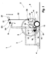
- a wheelchair 1 is equipped with a pushing aid 2.
- the one in the figures shown only schematically by mapping the right side of the wheelchair Wheelchair 1 comprises a frame 3, at the front end on the underside Swivel wheels 4 are articulated.
- In the area of the rear end of the Wheelchairs 1 are two large rear wheels 5, of which in the Figures only the right rear wheel 5 is shown.
- the frame 3 of the Wheelchair 1 comprises two parallel to each other at its rear upper end push handles 6 pointing in the direction of travel, at the ends of each a push handle extension 7 is arranged.
- the pushing aid 2 of the wheelchair 1 consists essentially of one Drive unit 8 comprising an electric motor 9, two accumulators 10, 10 'a gear 11 and two drive wheels arranged parallel to one another 12, of which the left in the direction of travel is shown in the figures is.
- the axis of rotation of the drive wheels 12 is basically parallel to Axis of rotation of the rear wheels 5 arranged.
- the drive unit 8 is over two rubber blocks 13 running parallel to each other in the direction of travel first connecting means 14 connected.
- These first lanyards 14 each comprise a wheelchair side, made up of two individual ones Tabs 15, 16 formed U-shaped receptacle, in the openings introduced for performing a locking bolt 17 are.
- the locking bolt 17 is movable in its longitudinal direction stored and can by a Bowden cable, not shown in the figures be operated.
- the first connecting means 14 act in the in FIG Figure 1 shown mounted position of the pushing aid 2 on the wheelchair 1 together with a connecting tongue 18, through which also the locking bolt 17 reaches through.
- the clear width of the through the tabs 15, 16 formed recording corresponds essentially to the strength the connecting tongue 18, so that in the assembled position of the Pushing aid 2 rigidly on the first connecting means 14 on the wheelchair 1 the wheelchair 1 are attached.
- the connecting tongue 18 is in turn on a mounting plate 19 attached to the frame side.
- the mounting plate 19 comprises a hole pattern, so that the mounting plate 19 at different Wheelchairs can be attached.
- the mounting plate 19 and the connecting tongue 18 arranged thereon constitute the second connecting means represents.
- a push rod 20 is arranged to pivot about the pivot axis D 2 in vertical directions upwards and downwards.
- the push rod 20 is coupled to the pivot axis D 2 via a link 21.
- the upper end of a push rod 22 is also articulated, the lower end of which is in turn articulated to the drive unit 8.
- the axes of rotation of the push rod 22 on the one hand with the handlebar 21 and on the other hand with the drive unit 8 are denoted by D 3 and D 4 .
- the four axes D 1 to D 4 define a link system, in which the drive unit 8 or the swing arm realized thereby and the link 21 represent the wishbones and the push rod 22 a movable longitudinal link.
- FIG. 2 shows a schematic plan view of the arrangement of the push rod 20 with the handlebar 21 and its attachment in the push handle extensions 7.
- the arrangement of the articulated connections D 2 and D 3 can also be seen .
- the drive unit 8 located on a swing arm are the first connecting means 14 in FIG adjacent rubber blocks 13 and the drive unit 8 schematized shown.
- two rubber blocks 13 arranged parallel to one another are provided so that a greater rigidity acting in the direction of travel this articulated connection is achieved (see FIG. 3b).
- the swiveling of the drive unit 8 is of the dimensioning and the material properties of the used rubber blocks 13 dependent.
- FIG. 4 shows an intermediate position while the drive unit 8 is being raised.
- the raised position of the drive unit 8 can be locked.
- Such locking can be realized, for example, in that the pressure rod 22 has a U-shaped configuration in the region of the pivot axis D 2 , so that the push rod 20 can be pivoted open beyond the dead center and is held in this position by a stop.
- the first step is to use pushing aid 2 approached the wheelchair 1, as shown in Figure 5a.
- the drive unit 8 of the pushing aid 2 With further Retracting the drive unit 8 of the pushing aid 2 into the between the space left of the wheelchair 1 is left behind 5 lower tab 16 of the first connecting means 14 on a guide rail 23 placed on the top, so that only by further insertion the drive unit 8, the connecting tongue 18 into the through the tabs 15, 16 formed recording is introduced.
- the locking bolt 17 is actuated, so that this shown in its Figure 1, the tabs 15, 16 and the connecting tongue 18 pervasive position is brought. Subsequently or else the push rod 20 is on the push handle extensions 7 has been arranged.
Landscapes
- Health & Medical Sciences (AREA)
- Life Sciences & Earth Sciences (AREA)
- Animal Behavior & Ethology (AREA)
- General Health & Medical Sciences (AREA)
- Public Health (AREA)
- Veterinary Medicine (AREA)
- Handcart (AREA)
- Time Recorders, Dirve Recorders, Access Control (AREA)
Applications Claiming Priority (2)
| Application Number | Priority Date | Filing Date | Title |
|---|---|---|---|
| DE1999118605 DE19918605C1 (de) | 1999-04-23 | 1999-04-23 | Rollstuhl mit einer Schiebehilfe |
| DE19918605 | 1999-04-23 |
Publications (2)
| Publication Number | Publication Date |
|---|---|
| EP1046384A2 true EP1046384A2 (fr) | 2000-10-25 |
| EP1046384A3 EP1046384A3 (fr) | 2000-11-15 |
Family
ID=7905702
Family Applications (1)
| Application Number | Title | Priority Date | Filing Date |
|---|---|---|---|
| EP00107443A Withdrawn EP1046384A3 (fr) | 1999-04-23 | 2000-04-06 | Fauteuil roulant avec aide de poussée |
Country Status (2)
| Country | Link |
|---|---|
| EP (1) | EP1046384A3 (fr) |
| DE (2) | DE19918605C1 (fr) |
Cited By (2)
| Publication number | Priority date | Publication date | Assignee | Title |
|---|---|---|---|---|
| EP2033609A2 (fr) | 2007-09-07 | 2009-03-11 | Holdingselskabet MKR Finans ApS | Unité de propulsion pour fauteuil roulant |
| EP2008629A3 (fr) * | 2007-06-28 | 2009-09-09 | Dane Industries, Inc. | Transporteur pour fauteuil roulant |
Families Citing this family (9)
| Publication number | Priority date | Publication date | Assignee | Title |
|---|---|---|---|---|
| DE10048532C1 (de) * | 2000-09-30 | 2001-08-09 | Rehatechnik Heymer Gmbh | Rollstuhl |
| DE10141566C1 (de) * | 2001-08-24 | 2002-10-31 | Alber Ulrich Gmbh & Co Kg | Bedienungselement für eine Antriebsvorrichtung |
| DE20114733U1 (de) * | 2001-08-31 | 2001-11-22 | Rothenburg, Bernd, 12167 Berlin | Einrichtung zur Kopplung eines Rolleraggregates an Rollstuhlvehikel zum Zwecke des Anschiebens |
| US7857342B2 (en) | 2005-06-07 | 2010-12-28 | Dane Technologies, Inc. | Hitch assembly |
| DE102006016568B4 (de) * | 2006-04-06 | 2008-12-24 | Ulrich Alber Gmbh | Schiebehilfe für einen Rollstuhl |
| NZ575468A (en) | 2006-09-13 | 2010-12-24 | Peter Raymond March | An improved lifting and transportation device |
| DE102007062406B4 (de) * | 2007-12-20 | 2010-04-15 | Herbert Burdich | Gehhilfe mit Antriebsmodul |
| ES2375297T3 (es) * | 2008-07-08 | 2012-02-28 | Wu's Tech Co., Ltd. | Estructura de silla de ruedas. |
| DE202022103451U1 (de) | 2022-06-21 | 2022-07-13 | Rehatechnik Heymer Gmbh | System umfassend einen Rollstuhl und eine Schiebehilfe |
Citations (1)
| Publication number | Priority date | Publication date | Assignee | Title |
|---|---|---|---|---|
| US592427A (en) | 1897-10-26 | Cut-out for electric-signal boxes |
Family Cites Families (5)
| Publication number | Priority date | Publication date | Assignee | Title |
|---|---|---|---|---|
| CH641667A5 (de) * | 1980-10-16 | 1984-03-15 | Sks Metallbau Ag | Zusatz-elektroantrieb fuer krankenrollstuehle. |
| US4515385A (en) * | 1981-06-08 | 1985-05-07 | Christian Dixon W | Wheelchair and attachment therefor |
| IL77966A (en) * | 1986-02-24 | 1991-03-10 | Propel Partnership 1987 | Wheelchair drive |
| DK204590D0 (da) * | 1990-08-27 | 1990-08-27 | Knud Raun | Koerestol med drivaggregat, samt drivaggregat til koerestole |
| DE19539487A1 (de) * | 1995-10-24 | 1997-04-30 | Alber Ulrich Gmbh | Antriebs- und Bremshilfsvorrichtung für Rollstühle |
-
1999
- 1999-04-23 DE DE1999118605 patent/DE19918605C1/de not_active Expired - Fee Related
-
2000
- 2000-02-25 DE DE20003481U patent/DE20003481U1/de not_active Expired - Lifetime
- 2000-04-06 EP EP00107443A patent/EP1046384A3/fr not_active Withdrawn
Patent Citations (1)
| Publication number | Priority date | Publication date | Assignee | Title |
|---|---|---|---|---|
| US592427A (en) | 1897-10-26 | Cut-out for electric-signal boxes |
Cited By (3)
| Publication number | Priority date | Publication date | Assignee | Title |
|---|---|---|---|---|
| EP2008629A3 (fr) * | 2007-06-28 | 2009-09-09 | Dane Industries, Inc. | Transporteur pour fauteuil roulant |
| EP2033609A2 (fr) | 2007-09-07 | 2009-03-11 | Holdingselskabet MKR Finans ApS | Unité de propulsion pour fauteuil roulant |
| EP2033609A3 (fr) * | 2007-09-07 | 2009-09-09 | Holdingselskabet MKR Finans ApS | Unité de propulsion pour fauteuil roulant |
Also Published As
| Publication number | Publication date |
|---|---|
| EP1046384A3 (fr) | 2000-11-15 |
| DE19918605C1 (de) | 2000-03-16 |
| DE20003481U1 (de) | 2000-06-21 |
Similar Documents
| Publication | Publication Date | Title |
|---|---|---|
| EP2192026B1 (fr) | Machine de traction agricole | |
| DE102018206225A1 (de) | Roller und Verfahren zum Bedienen eines Rollers | |
| DE3912194C2 (de) | Fahrzeug | |
| DE4409324A1 (de) | Sicherheitsfußhebelwerk für ein Kraftfahrzeug | |
| DE3527145C2 (fr) | ||
| DE19918605C1 (de) | Rollstuhl mit einer Schiebehilfe | |
| EP1925754A1 (fr) | Excavatrice combinée route-rail | |
| DE102011122660B4 (de) | Vorsatzgerät für Feldhäcksler mit integriertem Fahrwerk | |
| EP1099575A1 (fr) | Dispositif d'accouplement pour un véhicule automobile | |
| DE3200157C2 (fr) | ||
| DE102008013453B4 (de) | Rollstuhl-Radstandsverstellung durch Rollstuhlnutzer ohne abzunehmen der Räder | |
| DE19958994C1 (de) | Rollstuhl | |
| DE2651936A1 (de) | Strassenfahrzeug, insbesondere transportanhaenger | |
| DE3740028C2 (de) | Straßenfahrzeug | |
| DE4023690A1 (de) | Motorgetriebener, nachgefuehrter golfwagen | |
| EP1355821B1 (fr) | Attelage de bicyclette | |
| DE10224289A1 (de) | Fahrzeug, angetrieben mit Brennkraftmaschine oder Elektromotor | |
| EP2216232B1 (fr) | Ensemble carrosse de moteur et véhicule de traction correspondant | |
| DE102006032845B4 (de) | Zusatzantriebsvorrichtung für manuelle Rollstühle | |
| DE102017123395B4 (de) | Ankopplungsvorrichtung eines Rollstuhles an ein Fahrrad | |
| DE4239528C2 (de) | Kupplungsvorrichtung | |
| DE19959929C1 (de) | Rollstuhl | |
| DE19726311C2 (de) | Reisekoffer | |
| EP4467431A1 (fr) | Véhicule léger, notamment vélo de transport | |
| AT397637B (de) | Fahrzeug, das sowohl für eine fahrt auf strassen als auch für eine fahrt auf schienen eingerichtet ist |
Legal Events
| Date | Code | Title | Description |
|---|---|---|---|
| PUAI | Public reference made under article 153(3) epc to a published international application that has entered the european phase |
Free format text: ORIGINAL CODE: 0009012 |
|
| PUAL | Search report despatched |
Free format text: ORIGINAL CODE: 0009013 |
|
| AK | Designated contracting states |
Kind code of ref document: A2 Designated state(s): AT BE CH CY DE DK ES FI FR GB GR IE IT LI LU MC NL PT SE |
|
| AX | Request for extension of the european patent |
Free format text: AL;LT;LV;MK;RO;SI |
|
| AK | Designated contracting states |
Kind code of ref document: A3 Designated state(s): AT BE CH CY DE DK ES FI FR GB GR IE IT LI LU MC NL PT SE |
|
| AX | Request for extension of the european patent |
Free format text: AL;LT;LV;MK;RO;SI |
|
| 17P | Request for examination filed |
Effective date: 20010209 |
|
| AKX | Designation fees paid |
Free format text: AT BE CH CY DE DK ES FI FR GB GR IE IT LI LU MC NL PT SE |
|
| STAA | Information on the status of an ep patent application or granted ep patent |
Free format text: STATUS: THE APPLICATION HAS BEEN WITHDRAWN |
|
| 17Q | First examination report despatched |
Effective date: 20041207 |
|
| 18W | Application withdrawn |
Effective date: 20050107 |