EP1046403B1 - Blutzirkulationshilfsvorrichtung mit einer kontinuierlichen blutflusspumpe - Google Patents
Blutzirkulationshilfsvorrichtung mit einer kontinuierlichen blutflusspumpe Download PDFInfo
- Publication number
- EP1046403B1 EP1046403B1 EP98961572A EP98961572A EP1046403B1 EP 1046403 B1 EP1046403 B1 EP 1046403B1 EP 98961572 A EP98961572 A EP 98961572A EP 98961572 A EP98961572 A EP 98961572A EP 1046403 B1 EP1046403 B1 EP 1046403B1
- Authority
- EP
- European Patent Office
- Prior art keywords
- blood
- point
- flow rate
- amplitude
- pump
- Prior art date
- Legal status (The legal status is an assumption and is not a legal conclusion. Google has not performed a legal analysis and makes no representation as to the accuracy of the status listed.)
- Expired - Lifetime
Links
- 230000017531 blood circulation Effects 0.000 title claims abstract description 60
- 210000004369 blood Anatomy 0.000 claims abstract description 87
- 239000008280 blood Substances 0.000 claims abstract description 87
- 238000001514 detection method Methods 0.000 claims abstract description 40
- 230000008859 change Effects 0.000 claims description 23
- 230000004087 circulation Effects 0.000 description 26
- 230000001276 controlling effect Effects 0.000 description 17
- 230000002861 ventricular Effects 0.000 description 17
- 230000010349 pulsation Effects 0.000 description 16
- 238000000034 method Methods 0.000 description 15
- 230000000747 cardiac effect Effects 0.000 description 10
- 230000036772 blood pressure Effects 0.000 description 9
- 230000000875 corresponding effect Effects 0.000 description 9
- 238000012544 monitoring process Methods 0.000 description 9
- 230000000541 pulsatile effect Effects 0.000 description 8
- 230000007423 decrease Effects 0.000 description 7
- 238000002474 experimental method Methods 0.000 description 7
- 238000003745 diagnosis Methods 0.000 description 6
- 230000000694 effects Effects 0.000 description 6
- 230000009467 reduction Effects 0.000 description 6
- 230000004075 alteration Effects 0.000 description 5
- 238000010586 diagram Methods 0.000 description 5
- 238000006073 displacement reaction Methods 0.000 description 5
- 208000010496 Heart Arrest Diseases 0.000 description 3
- 230000035487 diastolic blood pressure Effects 0.000 description 3
- 210000005240 left ventricle Anatomy 0.000 description 3
- 238000005259 measurement Methods 0.000 description 3
- 241000282472 Canis lupus familiaris Species 0.000 description 2
- 238000004458 analytical method Methods 0.000 description 2
- 210000001765 aortic valve Anatomy 0.000 description 2
- 230000015572 biosynthetic process Effects 0.000 description 2
- 210000004351 coronary vessel Anatomy 0.000 description 2
- 230000002596 correlated effect Effects 0.000 description 2
- 230000003247 decreasing effect Effects 0.000 description 2
- 238000013095 identification testing Methods 0.000 description 2
- 238000001802 infusion Methods 0.000 description 2
- 239000007788 liquid Substances 0.000 description 2
- 210000000056 organ Anatomy 0.000 description 2
- 230000010355 oscillation Effects 0.000 description 2
- 230000036513 peripheral conductance Effects 0.000 description 2
- 238000005086 pumping Methods 0.000 description 2
- 210000002966 serum Anatomy 0.000 description 2
- 238000012360 testing method Methods 0.000 description 2
- 229920002307 Dextran Polymers 0.000 description 1
- 206010019280 Heart failures Diseases 0.000 description 1
- 208000013875 Heart injury Diseases 0.000 description 1
- 241001465754 Metazoa Species 0.000 description 1
- 208000007536 Thrombosis Diseases 0.000 description 1
- 208000027418 Wounds and injury Diseases 0.000 description 1
- 230000003872 anastomosis Effects 0.000 description 1
- 210000000709 aorta Anatomy 0.000 description 1
- 210000002376 aorta thoracic Anatomy 0.000 description 1
- 230000002763 arrhythmic effect Effects 0.000 description 1
- 210000001367 artery Anatomy 0.000 description 1
- QVGXLLKOCUKJST-UHFFFAOYSA-N atomic oxygen Chemical compound [O] QVGXLLKOCUKJST-UHFFFAOYSA-N 0.000 description 1
- 230000037396 body weight Effects 0.000 description 1
- 230000010351 cardiac pulsation Effects 0.000 description 1
- 238000006243 chemical reaction Methods 0.000 description 1
- 238000004590 computer program Methods 0.000 description 1
- 230000006378 damage Effects 0.000 description 1
- 230000018044 dehydration Effects 0.000 description 1
- 238000006297 dehydration reaction Methods 0.000 description 1
- 230000001419 dependent effect Effects 0.000 description 1
- 238000011161 development Methods 0.000 description 1
- 208000037265 diseases, disorders, signs and symptoms Diseases 0.000 description 1
- 239000000284 extract Substances 0.000 description 1
- 238000002695 general anesthesia Methods 0.000 description 1
- 238000005534 hematocrit Methods 0.000 description 1
- 230000006872 improvement Effects 0.000 description 1
- 238000011534 incubation Methods 0.000 description 1
- 208000014674 injury Diseases 0.000 description 1
- 230000003601 intercostal effect Effects 0.000 description 1
- 210000005248 left atrial appendage Anatomy 0.000 description 1
- 150000002632 lipids Chemical class 0.000 description 1
- 230000007774 longterm Effects 0.000 description 1
- 210000004115 mitral valve Anatomy 0.000 description 1
- 230000008035 nerve activity Effects 0.000 description 1
- 229910052760 oxygen Inorganic materials 0.000 description 1
- 239000001301 oxygen Substances 0.000 description 1
- 230000002093 peripheral effect Effects 0.000 description 1
- 230000035790 physiological processes and functions Effects 0.000 description 1
- 230000036316 preload Effects 0.000 description 1
- 230000008569 process Effects 0.000 description 1
- 102000004169 proteins and genes Human genes 0.000 description 1
- 108090000623 proteins and genes Proteins 0.000 description 1
- 238000000611 regression analysis Methods 0.000 description 1
- 210000005241 right ventricle Anatomy 0.000 description 1
- 230000035939 shock Effects 0.000 description 1
- 230000002889 sympathetic effect Effects 0.000 description 1
- 210000000115 thoracic cavity Anatomy 0.000 description 1
- 238000009423 ventilation Methods 0.000 description 1
Images




Classifications
-
- A—HUMAN NECESSITIES
- A61—MEDICAL OR VETERINARY SCIENCE; HYGIENE
- A61M—DEVICES FOR INTRODUCING MEDIA INTO, OR ONTO, THE BODY; DEVICES FOR TRANSDUCING BODY MEDIA OR FOR TAKING MEDIA FROM THE BODY; DEVICES FOR PRODUCING OR ENDING SLEEP OR STUPOR
- A61M60/00—Blood pumps; Devices for mechanical circulatory actuation; Balloon pumps for circulatory assistance
- A61M60/40—Details relating to driving
- A61M60/403—Details relating to driving for non-positive displacement blood pumps
- A61M60/408—Details relating to driving for non-positive displacement blood pumps the force acting on the blood contacting member being mechanical, e.g. transmitted by a shaft or cable
- A61M60/411—Details relating to driving for non-positive displacement blood pumps the force acting on the blood contacting member being mechanical, e.g. transmitted by a shaft or cable generated by an electromotor
-
- A—HUMAN NECESSITIES
- A61—MEDICAL OR VETERINARY SCIENCE; HYGIENE
- A61M—DEVICES FOR INTRODUCING MEDIA INTO, OR ONTO, THE BODY; DEVICES FOR TRANSDUCING BODY MEDIA OR FOR TAKING MEDIA FROM THE BODY; DEVICES FOR PRODUCING OR ENDING SLEEP OR STUPOR
- A61M60/00—Blood pumps; Devices for mechanical circulatory actuation; Balloon pumps for circulatory assistance
- A61M60/10—Location thereof with respect to the patient's body
- A61M60/104—Extracorporeal pumps, i.e. the blood being pumped outside the patient's body
-
- A—HUMAN NECESSITIES
- A61—MEDICAL OR VETERINARY SCIENCE; HYGIENE
- A61M—DEVICES FOR INTRODUCING MEDIA INTO, OR ONTO, THE BODY; DEVICES FOR TRANSDUCING BODY MEDIA OR FOR TAKING MEDIA FROM THE BODY; DEVICES FOR PRODUCING OR ENDING SLEEP OR STUPOR
- A61M60/00—Blood pumps; Devices for mechanical circulatory actuation; Balloon pumps for circulatory assistance
- A61M60/20—Type thereof
- A61M60/205—Non-positive displacement blood pumps
- A61M60/216—Non-positive displacement blood pumps including a rotating member acting on the blood, e.g. impeller
-
- A—HUMAN NECESSITIES
- A61—MEDICAL OR VETERINARY SCIENCE; HYGIENE
- A61M—DEVICES FOR INTRODUCING MEDIA INTO, OR ONTO, THE BODY; DEVICES FOR TRANSDUCING BODY MEDIA OR FOR TAKING MEDIA FROM THE BODY; DEVICES FOR PRODUCING OR ENDING SLEEP OR STUPOR
- A61M2205/00—General characteristics of the apparatus
- A61M2205/33—Controlling, regulating or measuring
- A61M2205/3331—Pressure; Flow
- A61M2205/3334—Measuring or controlling the flow rate
Definitions
- the present invention relates to a blood circulation assisting device using a continuous flow blood pump for blood feeding assistance.
- Pulsatile blood flow pumps for use in blood circulation assistance include positive-displacement pumps such as a diaphram type and a pusher plate type.
- the ejection of the positive-displacement pump is controlled so as to satisfy the needs of an organism by being driven with a complete-filling complete-ejection mode.
- the positive-displacement pumps face difficulty in the development as an artificial heart because their structure is complicated.
- continuous flow blood pumps have been developed for the purpose of assisting blood circulation in organism. They include not only typical types such as a centrifugal pump, an axial flow pump and a mixed flow pump, but ones which drive out blood by using a rotor, a precessional moving body, a swaying moving body, oscillations or undulations. Since their structure is simple and they can be manufactured at low cost, they show greater promise than the positive-displacement pumps. However, it is said that the continuous flow blood pumps are more difficult to control than the positive-displacement pumps.
- the method employs a mean motor current consumption and a hydraulic performance of the pump in use to estimate the pump flow rate, thereby maintaining a constant flow rate.
- the correlation can be obtained between a pump speed, a generated pressure head (pressure), a pump flow rate and a motor current consumption. Therefore, when the pump speed and the motor current consumption are known, the generated pressure head and flow rate of the pump can be estimated.
- the pump speed and the motor current consumption can be taken and used as internal data of the motor without using any specific sensor. As a result, the pump speed can be controlled with a simple structure so as to maintain the constant flow rate. (Cf., " Control of Centrifugal Blood Pump Based on the Motor Current", Tatsuhiko Iijima, et. al., Artificial Organs Vol. 21, No. 7, 1997, Japanese Society of Artificial Organs .)
- the controlling method cannot perform an appropriate blood circulation assistance in an organism.
- the blood flow rate needed by an organism varies very much according to the individual's condition. For example, size, state of activity and circulated blood volume of the individual have influence on the optimal blood flow rate.
- the usual cardiac output of an infant having a body weight of 10 kg is approximately 1 L/min, while the cardiac output of an adult during exertion may exceed 10 L/min. Therefore, the controlling method of merely maintaining the constant pump flow rate is not suitable for the appropriate blood circulation assistance in an organism.
- the motor current consumption is influenced by a kinematic viscosity of the liquid during feeding
- the liquid when the liquid is blood, for example, its change in character causes a large error in estimating the pump flow rate.
- What influences the kinematic viscosity of blood are factors such as the number of red cell (or hematocrit value), serum lipids value or serum whole protein value. These values fluctuate according to the physiological state of an organism.
- there is no method developed for continuously monitoring the kinematic viscosity or component concentration of blood it is difficult to achieve a method for controlling a blood feeding so as to obtain the desired flow rate free from the influence by the blood characteristic such as the kinematic viscosity
- the blood circulation assisting device according to the present invention is defined in independent claim 1 and dependant claim 2.
- the flow rate amplitude detection means provides an output according to the blood circulation state in an organism, so circulation assistance matching the blood circulation state in the organism can be achieved easily by the control based on the output.
- a continuous flow blood pump When a continuous flow blood pump is under usual operation, it drives out a continuous flow, and its consumption current does not show pulsation. On the other hand, unless the heart of an organism is under cardiac arrest or an arrhythmic state close to the cardiac arrest, it generates a pulsatile flow. Accordingly, when the continuous flow blood pump is used for circulation assistance in an organism, a pump flow that initially is a continuous flow is influenced by a pulsation of native cardiac output, and begins to show pulsation. As a result, current waveform of the motor, which drives the pump, also shows pulsation.
- total assistance refers to the case where cardiac output of an organism is not seen, and the blood pump drives out all the blood. However, this does not necessarily mean cardiac arrest, so the heart of the organism may generate some pressure.
- partial assistance refers to the state where the cardiac output of an organism is apparent, and at the same time the blood pump also drives out blood.
- the index of current amplitude is a value obtained by dividing the amplitude of current fluctuation with simultaneous mean current value. The reason the index of current amplitude is used is as follows.
- the t-p point and t-i point correspond to t-point mentioned above.
- the points at which the assist condition of the pump turns from partial to total assistance are distinguished based on an identification technique.
- the point that is identified by systolic aortic pressure and systolic left ventricular pressure is termed the t-p point
- the point that is identified by the index of current amplitude is termed the t-i point.
- the t-point in this section refers to the t-i point.
- the t-point is a specific point that clearly appears as the motor speed increases.
- sucking occurs intermittently, corresponding to pulsation of the heart in an organism, and causing pulsation in blood flow in the pump.
- the sucking becomes apparent at the pump speed higher than the t-point, that is still higher than the speed when the circulation in the organism and the pump come extremely close to the continuous flow.
- the amplitude of the fluctuation of consumption current waveform becomes the smallest when coming close to a continuous flow, and becomes larger again when the sucking becomes distinct.
- This point is called s-point (originating from a "sucking point") in the present invention.
- the index of current amplitude becomes larger beyond the s-point.
- the t-point is the point at which the circulation assistance by the pump changes from partial to total assistance.
- the pump can generate a pressure head sufficient to drive out the entire venous return volume and maintain flow rate.
- the pressure head is a pressure difference between inlet and outlet tubes of the pump and heavily depends on the blood pressure of the feeding side in an organism. Since this blood pressure is defined by the venous return volume and peripheral vascular resistance in an organism, the t-point also depends mainly on the venous return volume and peripheral vascular resistance.
- the speed increase indicates an increase of the venous return when the blood pressure is unchanged.
- it indicates an increase of the blood pressure when the venous return is unchanged.
- the speed decrease indicates vice versa.
- Near the t-point means the range that provides practically sufficient accuracy to estimate the change of circulation state in an organism. For example, it is the speed within the range of ⁇ 2 to 3 % of the speed at the t-point.
- Controlling the pump speed based on the t-point is an example showing the possibility of the control corresponding to the circulation state in an organism with using the amplitude of flow rate fluctuation such as the amplitude of the motor current consumption fluctuation mentioned here. Therefore, a control base can be selected according to the specific purpose.
- the s-point is the point at which the pulsation of blood flow in the pump becomes apparent due to sucking.
- the amplitude of current value fluctuation is substantially zero at the s-point or near the s-point, reflecting that a continuous flow has been generated in the pump. Therefore, the current amplitude at the s-point can be used for detecting a problem in the blood inflow portion of the blood removing pipe in the pump; such as blood removal failure due to improper location of the blood removing pipe, formation of a thrombosis or other obstructions, or distinctive decrease of blood volume (dehydration or shock), thus controlling blood circulation assistance appropriately.
- the amplitude of current value fluctuation near the s-point provides the control satisfactory enough in an actual use.
- Near the s-point means the range that provides practically sufficient accuracy to estimate the change of circulation state in an organism. For example, it is the speed within the range of ⁇ 2 to 3 % of the speed at the s-point.
- substantially zero described above means the range of current amplitude that can be used for detecting the problems at the s-point or near the s-point and realize an appropriate control of blood circulation assistance.
- the s-point or near the s-point is the point at which distinctive sucking does not occur and the heart of an organism generates the lowest pressure. This means that the maximum effect of stress reduction of the heart can be obtained safely.
- controlling the pump speed so as to always exist at the s-point or near the s-point realizes the safe and maximum effect of stress reduction of the heart.
- controlling the pump speed so as always to be substantially between the t-point and the s-point realizes the safe and effective circulation assistance, which is neither too much nor too little for an organism and provides the maximum effect of stress reduction of the heart.
- the present invention uses a pulsation amplitude as this indicator for control.
- the indicator for control may be a numerical value that is made into an indicator based on a pulsation amplitude of the current value. Specifically, they may be such a value as the one obtained by dividing the amplitude of the current value fluctuation of a pumping motor with a mean current value or the one obtained by dividing the amplitude with a current consumption difference between open operation period and closed operation period at the same pump speed (theoretical maximum amplitude).
- "Open operation period” is the case where a pump is operated with the conduit, which is communicated with the outflow portion of the pump, being open.
- closed operation period is the case where a pump is operated with the conduit being closed.
- the present invention does not require the specific sensor such as the one for monitoring a blood character.
- Mere flow rate measurement can detect blood circulation.
- the flow rate measurement is not conducted directly with a flow rate sensor but indirectly with other measuring means.
- the indirect measuring means for example, motor consumption current of a continuous flow blood pump. Consumption current multiplied by voltage makes electric power, so the electric power may also be used. Since consumption current can be obtained as an internal data of a motor, a sensor is not needed, leading to simplification of the device, improvement of reliability and safety, increase of long-term durability, cost reduction, miniaturization, etc.
- a direct means of measuring flow rate is a flow rate sensor such as an ultrasonic flow meter. Since it is conventionally used as a sensor, the structure of the device is far simpler than in the case where a specific sensor for monitoring blood characteristics is needed.
- the pump used in the present invention may be any continuous flow blood pump and is not limited to a specific pump.
- the pump may be located either externally or internally, and the assisting period may be either short or long.
- a blood removal site and a blood feed site are not limited. Assistance may be either in the right ventricle or left ventricle.
- the present invention may be embodied in various modes in the following that are suitable for actual use, in addition to above basic configurations.
- An output corresponding to the flow rate may be obtained by using means for measuring a current consumption or a power consumption value of the motor for the continuous flow blood pump, whereby the flow rate detection means is configured Alternatively, an output corresponding to the flow rate is obtained by using a flow sensor disposed near the continuous flow blood pump, whereby the flow rate detection means is configured. In this manner, a simple device can be configured without any specific sensor for monitoring blood characteristics.
- the flow rate amplitude detection means may be configured so that it detects a maximum value and a minimum value of the output of the flow rate detection means at predetermined time intervals and outputs the maximum and the minimum value.
- the flow rate amplitude detection means is configured so that it detects a maximum value and a minimum value of the output of the flow rate detection means at predetermined time intervals and outputs a flow rate amplitude that is a difference between the maximum and the minimum values.
- the flow rate amplitude detection means is configured so that it detects a mean value and a fluctuation amplitude of output of the flow rate detection means at predetermined time intervals and outputs an amplitude index that is obtained by dividing the amplitude with the mean output. In this manner, the desired output according to a control method can be obtained.
- the blood circulation assisting device may be configured so that it includes a display means for displaying the output of the flow rate amplitude detection means and a means for manually operating and adjusting a speed of the motor, thereby providing a simple device that easily can perform appropriate blood circulation assistance.
- the blood circulation assisting device further may include a means for controlling a speed of the motor for driving the pump according to the output of the flow rate amplitude detection means so that the flow rate amplitude is within a predetermined range.
- it further includes a means for controlling a speed of the motor for driving the pump according to the output of the flow rate amplitude detection means so that the flow rate amplitude index is within a predetermined range.
- the controlling means may be configured as follows. With the device being attached to an organism, the motor speed of the continuous flow blood pump is changed, so that the t-point at which circulation assistance by the pump changes from partial to total assistance is detected based on an output change of the flow rate amplitude detection means caused by the change of the motor speed.
- the motor speed is controlled so as to be in a predetermined relationship to the motor speed at the detected t-point.
- the motor is controlled so as to have a speed at the t-point or near the t-point. In this manner, an optimal operation is realized according to a clinical condition of an organism.
- the controlling means may be configured as follows. With the device being attached to an organism, the motor speed is changed, so that the s-point, at which a fluctuation of the flow rate amplitude becomes distinctive because a blood inflow port of the blood removing pipe starts sucking on to a wall of the organism, is detected based on an output change of the flow rate amplitude detection means caused by the change of the motor speed. The motor speed is controlled so as to be in a predetermined relationship to the motor speed at the detected s-point.
- the s-point is detected similarly based on the flow rate amplitude index, and the motor speed is controlled so as to be in a predetermined relation to the motor speed at the detected s-point.
- the motor is controlled so as to have a speed corresponding to the speed between near the t-point and near the s-point.
- a blood circulation is assisted so that the flow rate amplitude at the s-point is as small as possible and substantially zero.
- the motor speed is controlled so that when the motor speed is changed within a predetermined range, a correlation between the motor speed and index of current amplitude is negative.
- the blood circulation assisting device of the present invention may be used in a diagnosis apparatus for blood circulation state.
- the motor speed of the continuous flow blood pump is changed, so that the t-point at which circulation assistance by the pump changes from partial to total assistance is detected based on an output change of the flow rate amplitude detection means caused by the change of the motor speed.
- An inflow state at a blood inflow port and/or filling state of a heart are detected based on the flow rate amplitude at the detected t-point or near the t-point.
- the t-point is detected in a similar manner, so that the change of the motor speed at the detected t-point or near the t-point is detected, and a change of circulation state in the organism is detected with the speed change.
- the motor speed at the t-point or near the t-point increases, unchanged blood pressure is judged as an increase of venous return or unchanged venous return is judged as an increase of blood pressure.
- the motor speed at the t-point or near the t-point decreases, unchanged blood pressure is judged as a decrease of venous return or unchanged venous return is judged as a decrease of blood pressure.
- Above configurations provide a diagnosis apparatus that can easily diagnose blood circulation state in an organism with a simple structure.
- the apparatus may be configured by using the above-described blood circulation assisting device, so that the s-point is detected as mentioned above, and an inflow state at the blood inflow port and/or filling state of a heart are detected based on the flow rate amplitude at the detected s-point or near the s-point.
- the s-point is detected in a similar manner, the speed at the detected s-point or near the s-point is detected, and a change of circulation state in the organism is diagnosed with the speed change.
- a diagnosis device for preventing an injury due to sucking from generating.
- a blood circulation assisting method in which the blood circulation assisting device with above configuration is attached to the organism to assist blood circulation can easily realize appropriate circulation assistance for a blood circulation state in the organism.
- a method for diagnosing an organism in which the diagnosis device with the above configuration is attached to the organism to diagnose a blood circulation state easily can diagnose a blood circulation state in the organism.
- Numeral 1 denotes a continuous flow blood pump, which may be of various types such as a centrifugal pump, an axial flow pump, a mixed flow pump and pumps that drive out blood by using a rotor, a precessional moving body, a swaying moving body or oscillations and undulations.
- a blood removing pipe 2 is connected to the inlet port of the pump 1, and a blood feeding pipe 3 is connected to the outlet port.
- a free end of the blood removing pipe 2 is attached to a blood removal site in an organism, and a free end of the blood feeding pipe 3 is attached to a blood feeding site.
- a motor 4 drives the pump 1.
- the motor 4 is connected to a power source 6 via a control unit 5.
- a current measuring unit 7 is connected so as to measure current consumption of the motor 4.
- An output of the current measuring unit 7 is applied to an amplitude detection unit 8.
- the amplitude detection unit 8 detects the amplitude of current value fluctuation from the output of the current measuring unit 7 and outputs the result to the control unit 5.
- the control unit 5 controls the speed of the motor 4 based on the output of the amplitude detection unit 8.
- the current measuring unit 7 extracts current waveform at a sample rate of 120 Hz for 3 seconds, for example, and outputs data processed with A/D conversion.
- the amplitude detection unit 8 calculates maximum and minimum values of the data and difference thereof to detect the amplitude of current fluctuation.
- the current value of the motor 4 detected by the current measuring unit 7 corresponds to a flow rate of the pump 1.
- an index of current amplitude which is an output of the amplitude detection unit 8 corresponds to amplitude of a flow rate.
- the current measuring unit 7 forms flow rate detection means and the amplitude detection unit 8 forms flow rate amplitude detection means.
- the amplitude detection unit 8 outputs an index of current amplitude that is obtained by dividing the amplitude of current fluctuation with simultaneous mean current value, rather than the amplitude of current fluctuation itself.
- the current measuring unit 7 is properly set at the time for measuring the amplitude.
- control unit 5 The following is an example of the control performed by the control unit 5.
- the control unit 5 changes speed of the motor 4 and identifies the t-point or the s-point by using the index of current amplitude, which is an output of the amplitude detection unit 8.
- the motor may be controlled based on the speed corresponding to the identified t-point or s-point. For example, the motor is controlled so as to maintain the speed near the t-point.
- the t-point or s-point is identified based on the characteristics indicated in the graph shown in Fig. 1 .
- the index of current amplitude shows a stable decrease between the t-point and the s-point.
- the motor speed and the index of current amplitude show a negative correlation. Therefore, it is possible to detect whether the speed of the motor 4 is within the speed range corresponding to that between the t-point and the s-point by forcing the speed of the motor 4 to change at constant time intervals in a sufficiently wide speed range, and then detecting whether the correlation above is positive or negative.
- a sufficiently wide speed range means that it is sufficient to eliminate a temporary fluctuation of the index of current amplitude, such as the fluctuation appearing at the speed higher than the s-point shown in Fig. 1 , and proper range may be selected clinically.
- the speed range where the motor speed and the index of current amplitude show negative correlation is detected, and the starting point thereof is identified the t-point.
- the end point of the speed range is detected and identified the s-point.
- the motor speed and the index of current amplitude show negative correlation can be used effectively for the control.
- the speed of the motor 4 is forced to change for a certain period of time, the state of correlation mentioned above is detected, and then the speed of the motor 4 is controlled so as to be within the range of negative correlation.
- the motor 4 is driven again within the other speed range. In this manner, the motor can be controlled easily so as to be within the speed range between the t-point and the s-point, without actually detecting the t-point and the s-point.
- the speed of the motor 4 may be increased or decreased within the predetermined range.
- the detecting timing of the t-point and the s-point or whether or not the motor speed is within the desired range as is described above may be selected suitably according to clinical conditions.
- the current measuring unit 7 is used as means for measuring flow rate by the pump 1 with the configuration in which current value provides a value corresponding to the flow rate.
- the flow rate may be directly measured with using a flow sensor.
- an ultrasonic flow meter can be attached to the blood feeding pipe 3, and the output thereof may be processed by the amplitude detection unit 8.
- the amplitude detection unit 8, which is flow rate amplitude detection means may just output the amplitude of the output fluctuation by the flow sensor, and it is not necessary to index the amplitude as in the case of using the current value of the motor 4 described above.
- t-p point the point that was identified by systolic aortic pressure and systolic left ventricular pressure was termed t-p point
- t-i point the point that was identified by the index of current amplitude
- the index of current amplitude peaked at the t-i point and showed the minimum value at the s-point. Both the t-i point and the s-point were distinctive and easily identified.
- the cardiac output was 0.92 L/min before attaching the pump.
- the graph in Fig. 1 shows pump blood flow rate of 1.1 L/min at the t-i point, which is substantially congruent with venous return volume.
- the pump blood flow rate increased from the t-i point to the s-point, the aortic pressure did not increase. This seems to reflect the ineffective blood flow increase such as reversed flow at aortic valve, rather than the effective blood flow increase to an organism.
- pump blood flow rate did not increase due to distinctive sucking.
- the pump speed is changed actively, and a computer automatically calculates the relationship between the speed and index of current amplitude.
- the changing operation of the speed may be performed constantly, intermittently or in the case where some kind of disorder is detected.
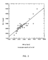
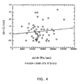
- the present experiment identified the t-point or the s-point by measuring systolic left ventricular pressure, index of current amplitude etc., within the pump speed variation range of 2000-5000 rpm.
- the pump speed variation range it is not always necessary for the pump speed variation range to be large as is described above.
- the pump speed is controlled to be near the t-point or the s-point (including each point), or between the t-point and the s-point including the vicinity of the t-point and the s-point.
- Eight beagle dogs underwent a formation of cardiac insufficiency due to a temporary obstruction of coronary artery and an infusion load test.
- the identification test of the t-point and the s-point was conducted by continuously changing the speed seven times temporarily, which were before coronary obstruction, during obstruction, 30, 60, 90 and 120 minutes after the obstruction, and post-infusion. The results from a total of 52 identification tests of measuring the t-points and the s-points were processed statistically.
- a continuous flow blood pump can be controlled in an optimal state matching a blood circulation state in an organism.
- the device with a simple structure achieves an optimal blood circulation assistance without any specific sensor.
- the present invention realizes the blood circulation assisting device with simple structure and excellent functions.
Landscapes
- Health & Medical Sciences (AREA)
- Heart & Thoracic Surgery (AREA)
- Engineering & Computer Science (AREA)
- Biomedical Technology (AREA)
- Mechanical Engineering (AREA)
- Anesthesiology (AREA)
- Cardiology (AREA)
- Hematology (AREA)
- Life Sciences & Earth Sciences (AREA)
- Animal Behavior & Ethology (AREA)
- General Health & Medical Sciences (AREA)
- Public Health (AREA)
- Veterinary Medicine (AREA)
- External Artificial Organs (AREA)
- Measuring Pulse, Heart Rate, Blood Pressure Or Blood Flow (AREA)
Claims (2)
- Blutkreislauf-Unterstützungsvorrichtung, umfassend:eine Durchfluss-Blutpumpe (1), aus einer Pumpe vom Nicht-Verdrängungstyp zur Bluteinspeisungshilfe,einen Motor (4) zum Antrieb der Durchfluss-Blutpumpe (1),eine Blutentnahmeleitung (2), mit einem Ende, das an einer Blutentnahmestelle in einem Organismus anbringbar ist, wobei das andere Ende mit einem Einströmteil der Durchfluss-Blutpumpe (1) verbunden ist,eine Bluteinspeisungsleitung (3), mit einem Ende, das an einer Bluteinspeisungsstelle in dem Organismus anbringbar ist, wobei das andere Ende mit einem Ausströmteil der Durchfluss-Blutpumpe (1) verbunden ist,eine Durchflussermittlungseinrichtung (7), um indirekt Daten zu erhalten, welche einer Blutdurchflussmenge entsprechen, die durch die Durchfluss-Blutpumpe (1) fließt undeine Kontrolleinrichtung (5) zur Regelung der Motorgeschwindigkeit,wobei Blut über die Blutentnahmeleitung (2) entnehmbar und über die Bluteinspeisungsleitung (3) durch die Duchfluss-Blutpumpe (1) ausgetrieben werden kann, um eine vorbestimmte Durchflussmenge zu erhalten und wobei die Durchflussermittlungseinrichtung (7) so konfiguriert ist, dass eine Ausgabe entsprechend der Durchflussmenge durch Messen eines Stromverbrauchs oder eines Energieverbrauchs des Motors (4) erhalten wird,dadurch gekennzeichnet, dassdie Blutkreislaufunterstützungsvorrichtung des Weiteren eine Durchflussamplituden-Ermittlungseinrichtung (8) umfasst, um aus einer Ausgabe der Durchflussermittlungseinrichtung (7) Daten zu erhalten, welche einer Fluktuationsamplitude der Durchflussmenge entsprechen, die Durchflussamplituden-Ermittlungseinrichtungen (8) eine mittlere Ausgabe und eine Ausgabe-Fluktuationsamplitude der Durchflussermittlungseinrichtung (7) in vorbestimmten Zeitintervallen ermittelt und einen Amplitudenindex ausgibt, welcher durch Dividieren der Fluktuationsamplitude mit der mittleren Ausgabe erhalten wird, unddie Kontrolleinrichtung (5) die Motorgeschwindigkeit entsprechend der Ausgabe der Durchflussamplituden-Ermittlungseinrichtung (8) auf eine Geschwindigkeit bei einem t-Punkt, einem s-punkt oder im Wesentlichen zwischen dem t-Punkt und dem s-Punkt regelt, wobei der t-Punkt und der s-Punkt ein Startpunkt bzw. ein Endpunkt eines Bereiches sind, innerhalb dessen der Amplitudenindex eine negative Korrelation mit einer Geschwindigkeit des Motors zeigt.
- Blutkreislaufunterstützungsvorrichtung gemäß Anspruch 1, worin die Kontrolleinrichtung (5) den t-Punkt oder s-Punkt identifizieren kann, indem der Motor (4) gezwungen wird, temporär seine Geschwindigkeit zu ändern, damit der Amplitudenindex variiert und die Korrelation zwischen dem Amplitudenindex und der Geschwindigkeit des Motors (4) auf Basis der Änderung des Amplitudenindex ermittelt wird.
Applications Claiming Priority (3)
| Application Number | Priority Date | Filing Date | Title |
|---|---|---|---|
| JP36752397 | 1997-12-27 | ||
| JP36752397 | 1997-12-27 | ||
| PCT/JP1998/005928 WO1999033502A1 (en) | 1997-12-27 | 1998-12-24 | Blood circulation auxiliary device using continuous blood flow pump and diagnosis device for blood circulation state in organism |
Publications (3)
| Publication Number | Publication Date |
|---|---|
| EP1046403A1 EP1046403A1 (de) | 2000-10-25 |
| EP1046403A4 EP1046403A4 (de) | 2001-01-17 |
| EP1046403B1 true EP1046403B1 (de) | 2010-12-15 |
Family
ID=18489527
Family Applications (1)
| Application Number | Title | Priority Date | Filing Date |
|---|---|---|---|
| EP98961572A Expired - Lifetime EP1046403B1 (de) | 1997-12-27 | 1998-12-24 | Blutzirkulationshilfsvorrichtung mit einer kontinuierlichen blutflusspumpe |
Country Status (6)
| Country | Link |
|---|---|
| US (1) | US6572530B1 (de) |
| EP (1) | EP1046403B1 (de) |
| JP (1) | JP3534419B2 (de) |
| CN (1) | CN1168507C (de) |
| DE (1) | DE69842053D1 (de) |
| WO (1) | WO1999033502A1 (de) |
Families Citing this family (45)
| Publication number | Priority date | Publication date | Assignee | Title |
|---|---|---|---|---|
| US7022100B1 (en) | 1999-09-03 | 2006-04-04 | A-Med Systems, Inc. | Guidable intravascular blood pump and related methods |
| CZ305727B6 (cs) * | 2000-03-27 | 2016-02-24 | The Cleveland Clinic Foundation | Pomocný přístroj pro pacienty s onemocněním srdce a způsob řízení průtoku krve krevní pumpou |
| JP4674978B2 (ja) * | 2001-02-01 | 2011-04-20 | Cyberdyne株式会社 | 心機能評価装置 |
| MXPA03007068A (es) * | 2001-02-07 | 2003-11-18 | Nephros Inc | Metodo y aparato para un modulo de administracion de hemodiafiltracion. |
| DE10123139B4 (de) * | 2001-04-30 | 2005-08-11 | Berlin Heart Ag | Verfahren zur Regelung einer Unterstützungspumpe für Fluidfördersysteme mit pulsatilem Druck |
| JP2005514094A (ja) * | 2002-01-08 | 2005-05-19 | マイクロメッド・テクノロジー・インコーポレイテッド | 心室破壊を検知するための方法およびシステム |
| US6991595B2 (en) * | 2002-04-19 | 2006-01-31 | Thoratec Corporation | Adaptive speed control for blood pump |
| JP4589798B2 (ja) * | 2005-04-26 | 2010-12-01 | 東レ・メディカル株式会社 | 脱血圧測定システム |
| JP4769937B2 (ja) * | 2005-08-10 | 2011-09-07 | 国立大学法人 東京医科歯科大学 | 遠心ポンプの流量及び揚程測定装置、及び、拍動する循環系の循環状態評価装置 |
| US20070142923A1 (en) | 2005-11-04 | 2007-06-21 | Ayre Peter J | Control systems for rotary blood pumps |
| US7963905B2 (en) | 2006-10-11 | 2011-06-21 | Thoratec Corporation | Control system for a blood pump |
| DE102007007198A1 (de) * | 2007-02-09 | 2008-08-14 | Maquet Cardiopulmonary Ag | Verfahren und Vorrichtung zur Überwachung und Optimierung eines durch eine Pumpe bewirkten Blutkreislaufs |
| JP5266464B2 (ja) * | 2007-05-10 | 2013-08-21 | ライニッシュ−ヴェストフェリッシェ・テクニッシェ・ホッホシューレ・アーヘン | 心機能変化評価装置 |
| EP2020246A1 (de) | 2007-08-03 | 2009-02-04 | Berlin Heart GmbH | Steuerung einer Rotationsblutpumpe mit wählbaren therapeutischen Optionen |
| US8475138B2 (en) * | 2007-08-27 | 2013-07-02 | Quest Medical, Inc. | Self-adaptive piston blood pump |
| JP5438332B2 (ja) | 2009-02-05 | 2014-03-12 | 昭和電線ケーブルシステム株式会社 | 高電圧電子機器用ケーブル |
| US8562507B2 (en) | 2009-02-27 | 2013-10-22 | Thoratec Corporation | Prevention of aortic valve fusion |
| US8449444B2 (en) | 2009-02-27 | 2013-05-28 | Thoratec Corporation | Blood flow meter |
| CA2802217A1 (en) | 2010-06-22 | 2011-12-29 | Thoratec Corporation | Fluid delivery system and method for monitoring fluid delivery system |
| TW201217010A (en) * | 2010-06-22 | 2012-05-01 | Thoratec Corp | Apparatus and method for modifying pressure-flow characteristics of a pump |
| CA2811604A1 (en) | 2010-09-24 | 2012-03-29 | Thoratec Corporation | Control of circulatory assist systems |
| EP3020426B1 (de) | 2010-09-24 | 2017-12-27 | Tc1 Llc | Erzeugung eines künstlichen pulses |
| JP2014500538A (ja) | 2010-10-12 | 2014-01-09 | タニス,ケヴィン ジェイ. | 医療機器 |
| US8613696B2 (en) * | 2011-08-15 | 2013-12-24 | Thoratec Corporation | Non-invasive diagnostics for ventricle assist device |
| DE102012100306B4 (de) * | 2012-01-13 | 2022-06-09 | Prominent Gmbh | Verfahren zur Adaption einer Dosierpumpe an die Viskosität des zu dosierenden Mediums |
| JP6345113B2 (ja) * | 2012-03-27 | 2018-06-20 | 株式会社サンメディカル技術研究所 | 補助人工心臓システム |
| WO2013145134A1 (ja) | 2012-03-27 | 2013-10-03 | 株式会社サンメディカル技術研究所 | 補助人工心臓ポンプ |
| EP4670759A3 (de) | 2012-08-31 | 2026-02-25 | Sanofi-Aventis Deutschland GmbH | Arzneimittelabgabevorrichtung |
| CN104768589B (zh) | 2012-09-05 | 2017-04-19 | 哈特威尔公司 | 集成流传感器的vad |
| US9737649B2 (en) | 2013-03-14 | 2017-08-22 | Smith & Nephew, Inc. | Systems and methods for applying reduced pressure therapy |
| AU2014236701B2 (en) | 2013-03-14 | 2018-07-19 | Smith & Nephew Inc. | Systems and methods for applying reduced pressure therapy |
| CA2920850C (en) | 2013-08-13 | 2022-08-30 | Smith & Nephew, Inc. | Systems and methods for applying reduced pressure therapy |
| US12133789B2 (en) | 2014-07-31 | 2024-11-05 | Smith & Nephew, Inc. | Reduced pressure therapy apparatus construction and control |
| EP3659638B1 (de) | 2014-07-31 | 2026-01-07 | Smith & Nephew, Inc. | Systeme und verfahren zur anwendung einer therapie mit reduziertem druck |
| US10874246B2 (en) * | 2014-10-06 | 2020-12-29 | Coffee Solutions, Llc | Beverage brewing systems and methods for using the same |
| CA2972691C (en) | 2014-12-30 | 2023-02-21 | Smith & Nephew, Inc. | Systems and methods for applying reduced pressure therapy |
| EP3240586B1 (de) | 2014-12-30 | 2024-08-28 | Smith & Nephew, Inc | System zur anwendung von therapien mit reduziertem druck |
| EP3135325A1 (de) * | 2015-08-24 | 2017-03-01 | Berlin Heart GmbH | Regeleinrichtung und verfahren für eine herzpumpe |
| US10632240B2 (en) * | 2015-10-23 | 2020-04-28 | Heartware, Inc. | Physiologically responsive blood pump for ischemia detection and treatment |
| AU2017218439B2 (en) | 2016-02-12 | 2022-07-28 | Smith & Nephew, Inc. | Systems and methods for detecting operational conditions of reduced pressure therapy |
| EP4059530B1 (de) | 2016-05-13 | 2025-07-23 | Smith & Nephew, Inc. | Automatische wundenverbindungsdetektion in unterdruckwundtherapiesystemen |
| EP3515526A1 (de) * | 2016-09-23 | 2019-07-31 | Heartware, Inc. | Feldorientierte steuerung zur kontrolle eines blutpumpenmotors |
| WO2020068333A1 (en) | 2018-09-25 | 2020-04-02 | Tc1 Llc | Adaptive speed control algorithms and controllers for optimizing flow in ventricular assist devices |
| KR20250016225A (ko) * | 2022-05-31 | 2025-02-03 | 소시에떼 데 프로듀이 네슬레 소시에떼아노님 | 유체 유량 |
| JP2026509570A (ja) * | 2023-03-30 | 2026-03-19 | ボストン サイエンティフィック サイムド,インコーポレイテッド | 大動脈弁閉鎖不全症の検出を含む経皮循環補助システムおよびデバイス |
Family Cites Families (5)
| Publication number | Priority date | Publication date | Assignee | Title |
|---|---|---|---|---|
| US5078741A (en) | 1986-10-12 | 1992-01-07 | Life Extenders Corporation | Magnetically suspended and rotated rotor |
| JPH08238310A (ja) * | 1995-03-06 | 1996-09-17 | Terumo Corp | 遠心ポンプ駆動制御装置及びそれを用いた体外循環血液回路 |
| JPH0956812A (ja) | 1995-08-23 | 1997-03-04 | Ntn Corp | 血液ポンプの制御方法 |
| US6129660A (en) | 1995-08-23 | 2000-10-10 | Ntn Corporation | Method of controlling blood pump |
| US6293901B1 (en) * | 1997-11-26 | 2001-09-25 | Vascor, Inc. | Magnetically suspended fluid pump and control system |
-
1998
- 1998-12-24 EP EP98961572A patent/EP1046403B1/de not_active Expired - Lifetime
- 1998-12-24 DE DE69842053T patent/DE69842053D1/de not_active Expired - Lifetime
- 1998-12-24 US US09/582,465 patent/US6572530B1/en not_active Expired - Fee Related
- 1998-12-24 CN CNB988138085A patent/CN1168507C/zh not_active Expired - Fee Related
- 1998-12-24 JP JP53480799A patent/JP3534419B2/ja not_active Expired - Fee Related
- 1998-12-24 WO PCT/JP1998/005928 patent/WO1999033502A1/ja not_active Ceased
Non-Patent Citations (1)
| Title |
|---|
| TATSUHIKO IIJIMA: "Control of Centrifugal Blood Pump Based on the Motor Current", ARTIFICIAL ORGANS, vol. 21, no. 7, 1997, pages 655 - 660, XP000995354 * |
Also Published As
| Publication number | Publication date |
|---|---|
| US6572530B1 (en) | 2003-06-03 |
| JP3534419B2 (ja) | 2004-06-07 |
| EP1046403A4 (de) | 2001-01-17 |
| CN1168507C (zh) | 2004-09-29 |
| WO1999033502A1 (en) | 1999-07-08 |
| CN1290183A (zh) | 2001-04-04 |
| DE69842053D1 (de) | 2011-01-27 |
| EP1046403A1 (de) | 2000-10-25 |
Similar Documents
| Publication | Publication Date | Title |
|---|---|---|
| US6572530B1 (en) | Blood circulation auxiliary device using continuous blood flow pump and diagnosis device for blood circulation state in organism | |
| JPWO1999033502A1 (ja) | 連続流血液ポンプを用いた血流循環補助装置および生体の血流循環状態の診断装置 | |
| US20230404421A1 (en) | Pressure Sensing Ventricular Assist Devices and Methods of Use | |
| AU2005247478B2 (en) | Sensorless flow estimation for implanted ventricle assist device | |
| JP7242636B2 (ja) | 血液ポンプ | |
| EP2145638B1 (de) | Vorrichtung zur bewertung von herzfunktionsänderungen | |
| JP5500348B2 (ja) | ポンプにより生じる血液循環を監視しかつ最適化する方法及び装置 | |
| US7988728B2 (en) | Physiological demand responsive control system | |
| EP2381975B1 (de) | Physiologische steuerung eines durchgehenden flusses eines vollständig künstlichen herzens | |
| US6878272B2 (en) | Dialyzing apparatus | |
| CN104822400A (zh) | 控制心室辅助设备(vad)的速度的方法和心室辅助设备 | |
| US6808627B2 (en) | Dialyzing apparatus | |
| JP3864944B2 (ja) | 連続流血液ポンプを用いた血流循環補助装置および生体の血流循環状態の診断装置 | |
| US6878273B2 (en) | Dialyzing apparatus | |
| US20040133061A1 (en) | Methods for detecting an abnormal condition of a blood pump system | |
| Sunagawa et al. | The contribution to hemodynamics even at very low pump speeds in the HVAD | |
| Taguchi et al. | A miniaturized centrifugal pump for assist circulation | |
| CN121731647A (zh) | 导管泵的位置监控装置、方法和心室辅助装置 | |
| AU2003265729B2 (en) | Physiological demand responsive control system | |
| Ayre et al. | Identifying physiologically significant pumping states in implantable rotary blood pumps using non-invasive system observers | |
| Kunst et al. | Dynamic Pumping Characteristics of the Hemopump® |
Legal Events
| Date | Code | Title | Description |
|---|---|---|---|
| PUAI | Public reference made under article 153(3) epc to a published international application that has entered the european phase |
Free format text: ORIGINAL CODE: 0009012 |
|
| 17P | Request for examination filed |
Effective date: 20000713 |
|
| AK | Designated contracting states |
Kind code of ref document: A1 Designated state(s): DE FR GB IT SE |
|
| A4 | Supplementary search report drawn up and despatched |
Effective date: 20001130 |
|
| AK | Designated contracting states |
Kind code of ref document: A4 Designated state(s): DE FR GB IT SE |
|
| 17Q | First examination report despatched |
Effective date: 20010504 |
|
| APBN | Date of receipt of notice of appeal recorded |
Free format text: ORIGINAL CODE: EPIDOSNNOA2E |
|
| APBR | Date of receipt of statement of grounds of appeal recorded |
Free format text: ORIGINAL CODE: EPIDOSNNOA3E |
|
| APAA | Appeal reference recorded |
Free format text: ORIGINAL CODE: EPIDOS REFN |
|
| APAF | Appeal reference modified |
Free format text: ORIGINAL CODE: EPIDOSCREFNE |
|
| APBT | Appeal procedure closed |
Free format text: ORIGINAL CODE: EPIDOSNNOA9E |
|
| GRAP | Despatch of communication of intention to grant a patent |
Free format text: ORIGINAL CODE: EPIDOSNIGR1 |
|
| RTI1 | Title (correction) |
Free format text: BLOOD CIRCULATION AUXILIARY DEVICE USING CONTINUOUS BLOOD FLOW PUMP |
|
| GRAJ | Information related to disapproval of communication of intention to grant by the applicant or resumption of examination proceedings by the epo deleted |
Free format text: ORIGINAL CODE: EPIDOSDIGR1 |
|
| GRAP | Despatch of communication of intention to grant a patent |
Free format text: ORIGINAL CODE: EPIDOSNIGR1 |
|
| GRAJ | Information related to disapproval of communication of intention to grant by the applicant or resumption of examination proceedings by the epo deleted |
Free format text: ORIGINAL CODE: EPIDOSDIGR1 |
|
| GRAP | Despatch of communication of intention to grant a patent |
Free format text: ORIGINAL CODE: EPIDOSNIGR1 |
|
| GRAS | Grant fee paid |
Free format text: ORIGINAL CODE: EPIDOSNIGR3 |
|
| GRAA | (expected) grant |
Free format text: ORIGINAL CODE: 0009210 |
|
| AK | Designated contracting states |
Kind code of ref document: B1 Designated state(s): DE FR GB IT SE |
|
| REG | Reference to a national code |
Ref country code: GB Ref legal event code: FG4D |
|
| REF | Corresponds to: |
Ref document number: 69842053 Country of ref document: DE Date of ref document: 20110127 Kind code of ref document: P |
|
| REG | Reference to a national code |
Ref country code: SE Ref legal event code: TRGR |
|
| PGFP | Annual fee paid to national office [announced via postgrant information from national office to epo] |
Ref country code: GB Payment date: 20101221 Year of fee payment: 13 |
|
| PLBE | No opposition filed within time limit |
Free format text: ORIGINAL CODE: 0009261 |
|
| STAA | Information on the status of an ep patent application or granted ep patent |
Free format text: STATUS: NO OPPOSITION FILED WITHIN TIME LIMIT |
|
| 26N | No opposition filed |
Effective date: 20110916 |
|
| REG | Reference to a national code |
Ref country code: DE Ref legal event code: R097 Ref document number: 69842053 Country of ref document: DE Effective date: 20110916 |
|
| PGFP | Annual fee paid to national office [announced via postgrant information from national office to epo] |
Ref country code: SE Payment date: 20111213 Year of fee payment: 14 Ref country code: FR Payment date: 20111219 Year of fee payment: 14 |
|
| PGFP | Annual fee paid to national office [announced via postgrant information from national office to epo] |
Ref country code: IT Payment date: 20111228 Year of fee payment: 14 |
|
| PGFP | Annual fee paid to national office [announced via postgrant information from national office to epo] |
Ref country code: DE Payment date: 20121219 Year of fee payment: 15 |
|
| PG25 | Lapsed in a contracting state [announced via postgrant information from national office to epo] |
Ref country code: SE Free format text: LAPSE BECAUSE OF NON-PAYMENT OF DUE FEES Effective date: 20121225 |
|
| GBPC | Gb: european patent ceased through non-payment of renewal fee |
Effective date: 20121224 |
|
| REG | Reference to a national code |
Ref country code: FR Ref legal event code: ST Effective date: 20130830 |
|
| PG25 | Lapsed in a contracting state [announced via postgrant information from national office to epo] |
Ref country code: GB Free format text: LAPSE BECAUSE OF NON-PAYMENT OF DUE FEES Effective date: 20121224 Ref country code: FR Free format text: LAPSE BECAUSE OF NON-PAYMENT OF DUE FEES Effective date: 20130102 |
|
| PG25 | Lapsed in a contracting state [announced via postgrant information from national office to epo] |
Ref country code: IT Free format text: LAPSE BECAUSE OF NON-PAYMENT OF DUE FEES Effective date: 20121224 |
|
| REG | Reference to a national code |
Ref country code: DE Ref legal event code: R119 Ref document number: 69842053 Country of ref document: DE |
|
| REG | Reference to a national code |
Ref country code: DE Ref legal event code: R119 Ref document number: 69842053 Country of ref document: DE Effective date: 20140701 |
|
| PG25 | Lapsed in a contracting state [announced via postgrant information from national office to epo] |
Ref country code: DE Free format text: LAPSE BECAUSE OF NON-PAYMENT OF DUE FEES Effective date: 20140701 |