EP1046416A2 - Verfahren zum Verhindern von Polymerisation in Dünnschichtverdampfern - Google Patents
Verfahren zum Verhindern von Polymerisation in Dünnschichtverdampfern Download PDFInfo
- Publication number
- EP1046416A2 EP1046416A2 EP00302853A EP00302853A EP1046416A2 EP 1046416 A2 EP1046416 A2 EP 1046416A2 EP 00302853 A EP00302853 A EP 00302853A EP 00302853 A EP00302853 A EP 00302853A EP 1046416 A2 EP1046416 A2 EP 1046416A2
- Authority
- EP
- European Patent Office
- Prior art keywords
- thin
- film type
- liquid
- evaporating device
- type evaporating
- Prior art date
- Legal status (The legal status is an assumption and is not a legal conclusion. Google has not performed a legal analysis and makes no representation as to the accuracy of the status listed.)
- Granted
Links
- 238000001704 evaporation Methods 0.000 title claims abstract description 222
- 239000010409 thin film Substances 0.000 title claims abstract description 154
- 238000000034 method Methods 0.000 title claims abstract description 55
- 238000006116 polymerization reaction Methods 0.000 title description 50
- 239000007788 liquid Substances 0.000 claims abstract description 248
- 239000000126 substance Substances 0.000 claims abstract description 95
- 239000007789 gas Substances 0.000 claims abstract description 66
- MYMOFIZGZYHOMD-UHFFFAOYSA-N Dioxygen Chemical compound O=O MYMOFIZGZYHOMD-UHFFFAOYSA-N 0.000 claims abstract description 56
- 229910001882 dioxygen Inorganic materials 0.000 claims abstract description 56
- 238000010438 heat treatment Methods 0.000 claims abstract description 56
- 239000002994 raw material Substances 0.000 claims abstract description 52
- 238000009736 wetting Methods 0.000 claims abstract description 33
- 238000003756 stirring Methods 0.000 claims abstract description 19
- 238000002156 mixing Methods 0.000 claims abstract description 6
- 230000008093 supporting effect Effects 0.000 claims description 15
- 230000008020 evaporation Effects 0.000 claims description 13
- CERQOIWHTDAKMF-UHFFFAOYSA-N Methacrylic acid Chemical group CC(=C)C(O)=O CERQOIWHTDAKMF-UHFFFAOYSA-N 0.000 claims description 11
- 238000011084 recovery Methods 0.000 claims description 11
- 238000007789 sealing Methods 0.000 claims description 7
- 230000003746 surface roughness Effects 0.000 claims description 7
- 150000002148 esters Chemical class 0.000 claims description 5
- 239000002699 waste material Substances 0.000 claims description 4
- 230000000379 polymerizing effect Effects 0.000 claims description 3
- 238000003466 welding Methods 0.000 claims description 2
- SMZOUWXMTYCWNB-UHFFFAOYSA-N 2-(2-methoxy-5-methylphenyl)ethanamine Chemical compound COC1=CC=C(C)C=C1CCN SMZOUWXMTYCWNB-UHFFFAOYSA-N 0.000 description 26
- NIXOWILDQLNWCW-UHFFFAOYSA-N 2-Propenoic acid Natural products OC(=O)C=C NIXOWILDQLNWCW-UHFFFAOYSA-N 0.000 description 26
- 238000009835 boiling Methods 0.000 description 17
- 238000004821 distillation Methods 0.000 description 16
- 229920000642 polymer Polymers 0.000 description 15
- 230000008569 process Effects 0.000 description 11
- 238000003860 storage Methods 0.000 description 11
- 238000000746 purification Methods 0.000 description 9
- 239000003112 inhibitor Substances 0.000 description 8
- 239000000047 product Substances 0.000 description 8
- 239000012535 impurity Substances 0.000 description 7
- 239000000463 material Substances 0.000 description 7
- 238000012546 transfer Methods 0.000 description 7
- XEEYBQQBJWHFJM-UHFFFAOYSA-N Iron Chemical group [Fe] XEEYBQQBJWHFJM-UHFFFAOYSA-N 0.000 description 6
- 229910052751 metal Inorganic materials 0.000 description 6
- 239000002184 metal Substances 0.000 description 6
- 230000036961 partial effect Effects 0.000 description 6
- -1 alkyl aminoalkyl ester Chemical class 0.000 description 5
- 230000015572 biosynthetic process Effects 0.000 description 5
- 238000001035 drying Methods 0.000 description 5
- 230000000694 effects Effects 0.000 description 5
- 238000005498 polishing Methods 0.000 description 5
- 125000004122 cyclic group Chemical group 0.000 description 4
- 239000000539 dimer Substances 0.000 description 4
- 238000007599 discharging Methods 0.000 description 4
- 239000010408 film Substances 0.000 description 4
- 230000014759 maintenance of location Effects 0.000 description 4
- 238000004519 manufacturing process Methods 0.000 description 4
- VLTRZXGMWDSKGL-UHFFFAOYSA-N perchloric acid Chemical compound OCl(=O)(=O)=O VLTRZXGMWDSKGL-UHFFFAOYSA-N 0.000 description 4
- 238000005979 thermal decomposition reaction Methods 0.000 description 4
- QTBSBXVTEAMEQO-UHFFFAOYSA-N Acetic acid Chemical compound CC(O)=O QTBSBXVTEAMEQO-UHFFFAOYSA-N 0.000 description 3
- WFDIJRYMOXRFFG-UHFFFAOYSA-N Acetic anhydride Chemical compound CC(=O)OC(C)=O WFDIJRYMOXRFFG-UHFFFAOYSA-N 0.000 description 3
- 229910000831 Steel Inorganic materials 0.000 description 3
- 230000008901 benefit Effects 0.000 description 3
- 239000003795 chemical substances by application Substances 0.000 description 3
- 238000010586 diagram Methods 0.000 description 3
- 230000001939 inductive effect Effects 0.000 description 3
- 230000002401 inhibitory effect Effects 0.000 description 3
- 229910052742 iron Inorganic materials 0.000 description 3
- 239000000203 mixture Substances 0.000 description 3
- 239000000178 monomer Substances 0.000 description 3
- 239000002904 solvent Substances 0.000 description 3
- 239000010959 steel Substances 0.000 description 3
- WJFKNYWRSNBZNX-UHFFFAOYSA-N 10H-phenothiazine Chemical compound C1=CC=C2NC3=CC=CC=C3SC2=C1 WJFKNYWRSNBZNX-UHFFFAOYSA-N 0.000 description 2
- GOXQRTZXKQZDDN-UHFFFAOYSA-N 2-Ethylhexyl acrylate Chemical compound CCCCC(CC)COC(=O)C=C GOXQRTZXKQZDDN-UHFFFAOYSA-N 0.000 description 2
- CYUZOYPRAQASLN-UHFFFAOYSA-N 3-prop-2-enoyloxypropanoic acid Chemical compound OC(=O)CCOC(=O)C=C CYUZOYPRAQASLN-UHFFFAOYSA-N 0.000 description 2
- NIXOWILDQLNWCW-UHFFFAOYSA-M Acrylate Chemical compound [O-]C(=O)C=C NIXOWILDQLNWCW-UHFFFAOYSA-M 0.000 description 2
- QIGBRXMKCJKVMJ-UHFFFAOYSA-N Hydroquinone Chemical compound OC1=CC=C(O)C=C1 QIGBRXMKCJKVMJ-UHFFFAOYSA-N 0.000 description 2
- NBIIXXVUZAFLBC-UHFFFAOYSA-N Phosphoric acid Chemical compound OP(O)(O)=O NBIIXXVUZAFLBC-UHFFFAOYSA-N 0.000 description 2
- OFOBLEOULBTSOW-UHFFFAOYSA-N Propanedioic acid Natural products OC(=O)CC(O)=O OFOBLEOULBTSOW-UHFFFAOYSA-N 0.000 description 2
- PPBRXRYQALVLMV-UHFFFAOYSA-N Styrene Chemical compound C=CC1=CC=CC=C1 PPBRXRYQALVLMV-UHFFFAOYSA-N 0.000 description 2
- QAOWNCQODCNURD-UHFFFAOYSA-N Sulfuric acid Chemical compound OS(O)(=O)=O QAOWNCQODCNURD-UHFFFAOYSA-N 0.000 description 2
- WGLPBDUCMAPZCE-UHFFFAOYSA-N Trioxochromium Chemical compound O=[Cr](=O)=O WGLPBDUCMAPZCE-UHFFFAOYSA-N 0.000 description 2
- 230000009471 action Effects 0.000 description 2
- 230000003197 catalytic effect Effects 0.000 description 2
- 229910000423 chromium oxide Inorganic materials 0.000 description 2
- 238000010276 construction Methods 0.000 description 2
- 230000007423 decrease Effects 0.000 description 2
- 230000003247 decreasing effect Effects 0.000 description 2
- 125000004494 ethyl ester group Chemical group 0.000 description 2
- 239000000945 filler Substances 0.000 description 2
- VZCYOOQTPOCHFL-UPHRSURJSA-N maleic acid Chemical compound OC(=O)\C=C/C(O)=O VZCYOOQTPOCHFL-UPHRSURJSA-N 0.000 description 2
- 239000011976 maleic acid Substances 0.000 description 2
- 150000004702 methyl esters Chemical class 0.000 description 2
- 239000003595 mist Substances 0.000 description 2
- 230000003647 oxidation Effects 0.000 description 2
- 238000007254 oxidation reaction Methods 0.000 description 2
- 229950000688 phenothiazine Drugs 0.000 description 2
- 230000002829 reductive effect Effects 0.000 description 2
- 230000000630 rising effect Effects 0.000 description 2
- DCKVNWZUADLDEH-UHFFFAOYSA-N sec-butyl acetate Chemical compound CCC(C)OC(C)=O DCKVNWZUADLDEH-UHFFFAOYSA-N 0.000 description 2
- 239000007921 spray Substances 0.000 description 2
- VZCYOOQTPOCHFL-UHFFFAOYSA-N trans-butenedioic acid Natural products OC(=O)C=CC(O)=O VZCYOOQTPOCHFL-UHFFFAOYSA-N 0.000 description 2
- NPSJHQMIVNJLNN-UHFFFAOYSA-N 2-ethylhexyl 4-nitrobenzoate Chemical compound CCCCC(CC)COC(=O)C1=CC=C([N+]([O-])=O)C=C1 NPSJHQMIVNJLNN-UHFFFAOYSA-N 0.000 description 1
- 239000004808 2-ethylhexylester Substances 0.000 description 1
- NLHHRLWOUZZQLW-UHFFFAOYSA-N Acrylonitrile Chemical compound C=CC#N NLHHRLWOUZZQLW-UHFFFAOYSA-N 0.000 description 1
- STNJBCKSHOAVAJ-UHFFFAOYSA-N Methacrolein Chemical compound CC(=C)C=O STNJBCKSHOAVAJ-UHFFFAOYSA-N 0.000 description 1
- MXRIRQGCELJRSN-UHFFFAOYSA-N O.O.O.[Al] Chemical compound O.O.O.[Al] MXRIRQGCELJRSN-UHFFFAOYSA-N 0.000 description 1
- QOSMNYMQXIVWKY-UHFFFAOYSA-N Propyl levulinate Chemical compound CCCOC(=O)CCC(C)=O QOSMNYMQXIVWKY-UHFFFAOYSA-N 0.000 description 1
- 238000005299 abrasion Methods 0.000 description 1
- 230000002411 adverse Effects 0.000 description 1
- PNEYBMLMFCGWSK-UHFFFAOYSA-N aluminium oxide Inorganic materials [O-2].[O-2].[O-2].[Al+3].[Al+3] PNEYBMLMFCGWSK-UHFFFAOYSA-N 0.000 description 1
- 229910000147 aluminium phosphate Inorganic materials 0.000 description 1
- 238000013459 approach Methods 0.000 description 1
- QVGXLLKOCUKJST-UHFFFAOYSA-N atomic oxygen Chemical compound [O] QVGXLLKOCUKJST-UHFFFAOYSA-N 0.000 description 1
- 230000005587 bubbling Effects 0.000 description 1
- CQEYYJKEWSMYFG-UHFFFAOYSA-N butyl acrylate Chemical compound CCCCOC(=O)C=C CQEYYJKEWSMYFG-UHFFFAOYSA-N 0.000 description 1
- 239000006227 byproduct Substances 0.000 description 1
- 238000006243 chemical reaction Methods 0.000 description 1
- 238000004891 communication Methods 0.000 description 1
- 238000009833 condensation Methods 0.000 description 1
- 230000005494 condensation Effects 0.000 description 1
- GCFAUZGWPDYAJN-UHFFFAOYSA-N cyclohexyl 3-phenylprop-2-enoate Chemical group C=1C=CC=CC=1C=CC(=O)OC1CCCCC1 GCFAUZGWPDYAJN-UHFFFAOYSA-N 0.000 description 1
- 238000009826 distribution Methods 0.000 description 1
- 239000003792 electrolyte Substances 0.000 description 1
- 238000002474 experimental method Methods 0.000 description 1
- 239000004744 fabric Substances 0.000 description 1
- 230000002349 favourable effect Effects 0.000 description 1
- 238000009499 grossing Methods 0.000 description 1
- 239000011346 highly viscous material Substances 0.000 description 1
- 125000002768 hydroxyalkyl group Chemical group 0.000 description 1
- 230000001976 improved effect Effects 0.000 description 1
- 230000009545 invasion Effects 0.000 description 1
- 230000002045 lasting effect Effects 0.000 description 1
- 239000010985 leather Substances 0.000 description 1
- 230000033001 locomotion Effects 0.000 description 1
- 239000010687 lubricating oil Substances 0.000 description 1
- 238000003754 machining Methods 0.000 description 1
- FPYJFEHAWHCUMM-UHFFFAOYSA-N maleic anhydride Chemical compound O=C1OC(=O)C=C1 FPYJFEHAWHCUMM-UHFFFAOYSA-N 0.000 description 1
- 230000007246 mechanism Effects 0.000 description 1
- 150000002734 metacrylic acid derivatives Chemical class 0.000 description 1
- 238000012986 modification Methods 0.000 description 1
- 230000004048 modification Effects 0.000 description 1
- 239000003921 oil Substances 0.000 description 1
- 239000001301 oxygen Substances 0.000 description 1
- 229910052760 oxygen Inorganic materials 0.000 description 1
- YXJYBPXSEKMEEJ-UHFFFAOYSA-N phosphoric acid;sulfuric acid Chemical compound OP(O)(O)=O.OS(O)(=O)=O YXJYBPXSEKMEEJ-UHFFFAOYSA-N 0.000 description 1
- 238000007517 polishing process Methods 0.000 description 1
- QQONPFPTGQHPMA-UHFFFAOYSA-N propylene Natural products CC=C QQONPFPTGQHPMA-UHFFFAOYSA-N 0.000 description 1
- 125000004805 propylene group Chemical group [H]C([H])([H])C([H])([*:1])C([H])([H])[*:2] 0.000 description 1
- 238000009877 rendering Methods 0.000 description 1
- 230000000754 repressing effect Effects 0.000 description 1
- 238000000926 separation method Methods 0.000 description 1
- HBMJWWWQQXIZIP-UHFFFAOYSA-N silicon carbide Chemical compound [Si+]#[C-] HBMJWWWQQXIZIP-UHFFFAOYSA-N 0.000 description 1
- 229910010271 silicon carbide Inorganic materials 0.000 description 1
- 238000007711 solidification Methods 0.000 description 1
- 230000008023 solidification Effects 0.000 description 1
- 238000005507 spraying Methods 0.000 description 1
- 238000003892 spreading Methods 0.000 description 1
- 230000007480 spreading Effects 0.000 description 1
- 229910001220 stainless steel Inorganic materials 0.000 description 1
- 239000010935 stainless steel Substances 0.000 description 1
- 239000004575 stone Substances 0.000 description 1
- 238000004381 surface treatment Methods 0.000 description 1
- 238000012719 thermal polymerization Methods 0.000 description 1
Images

Classifications
-
- B—PERFORMING OPERATIONS; TRANSPORTING
- B01—PHYSICAL OR CHEMICAL PROCESSES OR APPARATUS IN GENERAL
- B01D—SEPARATION
- B01D3/00—Distillation or related exchange processes in which liquids are contacted with gaseous media, e.g. stripping
- B01D3/34—Distillation or related exchange processes in which liquids are contacted with gaseous media, e.g. stripping with one or more auxiliary substances
- B01D3/343—Distillation or related exchange processes in which liquids are contacted with gaseous media, e.g. stripping with one or more auxiliary substances the substance being a gas
-
- B—PERFORMING OPERATIONS; TRANSPORTING
- B01—PHYSICAL OR CHEMICAL PROCESSES OR APPARATUS IN GENERAL
- B01D—SEPARATION
- B01D1/00—Evaporating
- B01D1/22—Evaporating by bringing a thin layer of the liquid into contact with a heated surface
- B01D1/222—In rotating vessels; vessels with movable parts
- B01D1/223—In rotating vessels; vessels with movable parts containing a rotor
- B01D1/225—In rotating vessels; vessels with movable parts containing a rotor with blades or scrapers
-
- Y—GENERAL TAGGING OF NEW TECHNOLOGICAL DEVELOPMENTS; GENERAL TAGGING OF CROSS-SECTIONAL TECHNOLOGIES SPANNING OVER SEVERAL SECTIONS OF THE IPC; TECHNICAL SUBJECTS COVERED BY FORMER USPC CROSS-REFERENCE ART COLLECTIONS [XRACs] AND DIGESTS
- Y10—TECHNICAL SUBJECTS COVERED BY FORMER USPC
- Y10S—TECHNICAL SUBJECTS COVERED BY FORMER USPC CROSS-REFERENCE ART COLLECTIONS [XRACs] AND DIGESTS
- Y10S203/00—Distillation: processes, separatory
- Y10S203/22—Accessories
Definitions
- This invention relates to a method for preventing polymerization of an easily polymerizable substance in a thin-film type evaporating device.
- the contrivances devoted to the recovery of a product aimed at from the solution entraining high-boiling substances includes a thin-film type evaporating device.
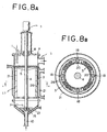
- the method for purifying an easily polymerizable substance will be described below with reference to Fig. 8A and Fig. 8B which illustrate one mode of the conventional vertical thin-film type evaporating device.
- the device mentioned above is provided with a rotary shaft (4) which is disposed on a mechanical seal mounting plate (7) through a mechanical seal part (8) as illustrated in Fig. 8A.
- the rotary shaft (4) penetrates the interior of the devices and reaches a bearing part (15) in the lower part of the device.
- This rotary shaft (4) has a liquid distributor plate (5) connected thereto and is rotated in concert with the operation of the stirring rotary shaft (4).
- Fig. 8B represents a cross section taken through the line a-a in Fig. 8A.
- a wiper (18) fixed with a supporting metal (20) and a rotor (17) for retaining a mist separator (26) are set in position through the distribution panel (5) as illustrated in Fig. 8B.
- the low-boiling substance is gasified, transferred to the upper part of the device via a mist separator (26), and discharged through a vapor outlet (2). Meanwhile, the high-boiling substance is allowed to descend to the interior of the device and discharged through an extracted liquid outlet (10).
- the feed material is moved from the liquid distributor plate (5) of the thin-film type evaporating device to the evaporating heating surface (3) and spread it out with a wiper (18) to form a very thin uniform liquid film. Since the liquid under treatment consequently has a short retention time and evaporates at a low temperature, the device is capable of evaporating a thermally unstable substance. Further, since the device is capable of forming a powerful thin film, it is applicable to a substance which produces a highly viscous residue after concentration and suitable for the distillation of an easily polymerizable substance.
- JP-B-06-53,711 discloses a method for purification which comprises forming a thin film 0.2 - 2 mm in thickness and evaporating the ester through the thin film with an average retention time in the range of 2 - 40 seconds.
- the official gazette of JP-A-11-12,222 also discloses a method for recovering acrylic acid from an acrylic acid solution containing a high-boiling substance of high viscosity by the use of a recovering column which is provided with a thin-film type evaporating device.
- Acrylic acid or methacrylic acid is liable to polymerize at a high temperature.
- the polymerization not only decreases the quantity of purified acrylic acid or methacrylic acid to be obtained as a product but also entails serious problems such as solidification of a polymer in the evaporating device, for example. This polymerization tends to occur in the portion of the thin-film type evaporating device in which the viscosity is particularly high.
- the distillation of acrylic acid is carried out in vacuum of a high degree at the lowest permissible temperature such as not higher than 100 °C for the purpose of preventing the polymerization, with a polymerization inhibitor such as phenothiazine or hydroquinone added to the distillation system. Since the boiling point of such a polymerization inhibitor is invariably higher than the boiling point of acrylic acid, consequently, the acrylic acid gas fails to include the polymerization inhibitor and the polymerization is not easily inhibited fully satisfactorily.
- the thin-film type evaporating device has a structural problem. Specifically, while the feed raw material is supplied to the evaporating heating surface (3) by the centrifugal force of the liquid distributor plate (5) annexed to the stirring rotary shaft (4) and subjected thereon to thermal distillation, the rotary shaft (4) is constantly kept in rotation during the operation of the device. This rotary shaft (4) penetrates the interior of the thin-film type evaporating device and connects with the rotary shaft driving part (9) disposed in the upper part of the device. The device is provided therein, for the sake of watertightness, with a mechanical seal (8) adapted for the rotary shaft.
- the mechanical seal (8) is one contrivance for preventing leakage of the vapor of distillation and, at the same time, keeping the motion of the rotary shaft (4) from obstruction, the vapor of distillation of an easily polymerizable substance is liable to adhere to the rotating part of the rotary shaft, forms a deposit of the polymer of the substance thereon, and consequently obstructs the rotation of the rotary shaft.
- the polymerization which is induced by the rotation of the rotary shaft (4) occurs also on the bearing part (15) in the device. Especially, at the extracted liquid outlet (10), the polymerization is liable to occur because the viscosity of the liquid in process is at a higher level than the feed raw material.
- the extracted liquid outlet (10) tends to suffer adhesion thereto of the condensate liquid of high viscosity and entail stagnation of the extracted liquid in the lower part thereof.
- the polymer obstructs the rotation of the stirring rotary shaft (4) and forms the cause for stopping the operation of distillation itself and the cause for decreasing the quantity of a product.
- the thin-film type evaporating device requires the interior thereof to be washed periodically and consequently puts an obstruction in the way of its lasting stable operation.
- the thin-film type evaporating device can be used as connected to a distillation column or a recovering column.
- the use of this device in this manner may possibly arise in a case of using the device as a re-boiler for reboiling the liquid extracted from a recovering column and, at the same time, supplying the vapor formed of a distillate component to the recovering column with the object of recovering an easily polymerizable substance aimed at through the top of the recovering column and, at the same time, circulating the liquid extracted through the bottom of the recovering column back to the thin-film type evaporating device.
- the wiper (18) When the liquid extracted from the recovering column is used as the feed raw material to the thin-film type evaporating device, the wiper (18) will possibly seize on the evaporating heating surface (3) and induce the liquid under treatment to polymerize owing to an increase in the viscosity thereof. If this polymerization occurs, acquisition of a distillate component or condensate liquid having relevant components in fixed concentrations will become difficult and manufacture of a stable product will be obstructed.
- the present inventors have discovered that polymerization arising in a thin-film type evaporating device can be effectively prevented by cyclically using a liquid extracted from the thin-film type evaporating device simultaneously with supplying a molecular oxygen-containing gas and adjusting the quantity of liquid per unit length of the evaporating heating surface of the device in the specific range.
- This invention has been established by the studies as a result. To be specific, this invention has the object of providing the following items (1) and (2).
- This invention concerns a method for preventing an easily polymerizable substance from being polymerized in a thin-film type evaporating device by supplying a solution of said easily polymerizable substance to the evaporating heating surface of said device by the centrifugal force of a stirring rotary shaft, characterized by mixing the vapor of distilled vapor of the substance with a molecular oxygen-containing gas and supplying the extracted liquid obtained from the bottom of the device or a solution having lower viscosity than said extracted liquid to a feed raw material inlet thereby adjusting the quantity of the wetting liquid or the solution per unit length of the evaporating heating surface in the range of 0.02 - 2 m 3 /mHr.
- a wide range of polymerizing monomers answer the description "easily polymerizable substance" used in this invention.
- the polymerizing monomer acrylic acid, methacrylic acid, maleic anhydride, styrene, acrylonitrile, and esters thereof, and derivatives thereof may be cited. They may further contain high-boiling substances, solvents, and mixtures of easily polymerizable substances with by-products occurring during the formation thereof.
- acrylic acid and esters methyl ester, ethyl ester, butyl ester, and 2-ethylhexyl ester
- methacrylic acid and esters methyl ester, ethyl ester, propyl ester, isopropyl ester, tertiary butyl ester, and cyclohexyl ester
- methacrylic acid, dimethylaminoethyl (meth)acrylate, and hydroxyalkyl (meth)acrylate may be cited.
- they may contain solvents and other impurities.
- the acrylic acid solution which contains an acrylic acid dimer, maleic acid, and other impurities may be cited as easily polymerizable substances in addition to acrylic acid in the bottoms obtained from the high-boiling impurity separating column.
- methacrylic acid and methacrylates for example, the mixture of methacrolein, acrylic acid, and acetic acid which is by-produced during the reaction of catalytic gas phase oxidation of methacrylic acid may be cited as an easily polymerizable substance in addition to methacrylic acid.
- This invention is characterized by supplying the extracted liquid from the liquid receiving part to the feed raw material inlet in such a manner that the quantity of a wetting liquid per unit length of the evaporating heating surface is in the range of 0.02 - 2 m 3 /Hr.
- the expression "quantity of wetting liquid per unit length of the evaporating heating surface" as used in this invention means the numerical value obtained by dividing the quantity of the wetting liquid extracted from the thin-film type evaporating device by the unit length of the wetted side as represented by the following equation.
- Quantity of wetting liquid per unit length of the evaporating heating surface [Quantity of liquid extracted from thin-film type evaporating device (m 3 /mHr)/ [ ⁇ ⁇ Inside diameter of evaporating heating surface of thin-film type evaporating device (m)]
- the feed raw material is gradually evaporated in accordance as it advances on an evaporating heating surface (3) in the device toward an extracted liquid outlet (10).
- the thickness of the film of the raw material on the evaporating heating surface (3) therefore, is different in the neighborhood of the raw material inlet (1) and in the neighborhood of the outlet (10) on the evaporating heating surface.
- the raw material tends to stagnate or polymerize unless the neighborhood of the outlet of the evaporating heating surface (3) incurring rise of viscosity secures the wetting liquid in a fixed quantity.
- the quantity of the wetting liquid at varying points of the evaporating heating surface of the thin-film type evaporating device is varied by the length of the evaporating heating surface, the heating temperature, the quantity of the raw material to be fed, the boiling point and the concentration of the easily polymerizable substance, etc.
- the present inventors have discovered that when the easily polymerizable substance mentioned above is used as the raw material feeding liquid, the polymerization of the easily polymerizable substance during the distillation thereof in the thin-film type evaporating device can be inhibited by supplying at least part of the extracted liquid to the raw material inlet (1) thereby securing the aforementioned quantity of the wetting liquid on the evaporating heating surface (3) throughout the entire length of the evaporating heating surface (3) and, at the same time, supplying a molecular oxygen-containing gas.
- a solution obtained somewhere else may be used. Even when the extracted liquid can be used, the solution obtained somewhere else may be used for the purpose of addition to the raw material to be fed.
- the treated liquid may be used as the extracted liquid.
- this liquid can be adapted for the recirculation and consequently enabled to enhance the yield of purification by thermally decomposing the dimer and converting it into an easily polymerizable substance aimed at.
- the present invention adopts the quantity of the liquid (m 3 /Hr) extracted from the thin-film type evaporating device as the criterion for judgment with the object of securing a fixed quantity of the wetting liquid also on the evaporating heating surface in the neighborhood of the extracted liquid outlet (10) in the thin-film type evaporating device.
- the evaporating heating surface (3) of the thin-film type evaporating device brings dryness on the extracted liquid outlet side thereof and constitutes itself a cause for inducing polymerization, depending on the magnitude of the amount of evaporation.
- the speed of evaporation and the quantity of evaporation are varied and the thickness of the film is varied by the difference in the content of the easily polymerizable substance in the raw material to be supplied and the difference in the heating temperature and the vapor pressure.
- the quantity of the wetting liquid can be easily adjusted and the polymerization can be prevented by adjusting the quantity of the extracted liquid to be circulated within the range mentioned above.
- the quantity of the wetting liquid on the evaporating heating surface (3) of the thin-film type evaporating device is required to be in the range of 0.02 - 2 m 3 /mHr. If the quantity of the wetting liquid exceeds 2 m 3 /mHr, the liquid will emit a splash, induce polymerization in the pipe, and cause clogging of the pipe. Conversely, if the quantity of the wetting liquid is less than 0.02 m 3 /mHr, the interior of the thin-film type evaporating device will be liable to dry on the surface and induce polymerization.
- the thin-film type evaporating device to be effectively used in this invention allows both the vertical and the horizontal type in structure.
- the device is not discriminated on account of the difference between the vertical type and the horizontal type.
- the range is preferred to be 0.3 - 1.5 m 3 /mHr.
- the horizontal type it is preferred to be 0.02 - 1 m 3 /mHr because the liquid is liable to emit a splash.
- the quantity of the wetting liquid varies even with the kind of the easily polymerizable substance.
- the quantity of the wetting liquid is preferred to be in the range of 0.2 - 2 m 3 /mHr. This specific range is effective in preventing polymerization because the evaporating heating surface is enabled to form a uniform liquid film in a relatively short period of time and prevented from easily drying.
- the quantity of the wetting liquid proper for this invention even in the thin-film type evaporating device having a fixed surface area and supplying the raw material in a fixed quantity, the quantity of the wetting liquid is variable.
- the quantity of the extracted liquid it is usual to adjust the quantity of the extracted liquid after the thin-film type evaporating device to be used has been set.
- This invention in respect that the quantity of the wetting liquid varies with the inside diameter of the evaporating heating surface of the thin-film type evaporating device, enables a thin-film type evaporating device capable of handling the wetting liquid in a quantity specified above to be selected in conformity with the process and consequently prevents polymerization which possibly occurs in the device.
- the thin-film type evaporating device can use steam, oil, etc. though not exclusively.
- the temperature of this heat transfer medium is preferably not higher than 200°C, and more preferably not higher than 180°C. If the temperature of the heat transfer medium is high, though this high temperature will prove favorable from the viewpoint of the quantity of the wetting liquid as by increasing the difference in temperature between the heat transfer medium and the raw material to be supplied and decreasing the evaporating heating surface and the inside diameter of the evaporating device, it will be at a disadvantage in possibly causing the raw material to succumb to polymerization owing to the increase in the temperature of the evaporating heating surface.
- the supply of the easily polymerizable substance to the stirring thin-film type evaporating device is not started until the external cylinder of the device is heated with a heat transfer medium.
- the speed of thermal decomposition or thermal polymerization of a substance is doubled for each rise of temperature by 10°C and that it is in direct proportion to the length of the heating time.
- the temperature inside the external cylinder of the stirring thin-film type evaporating device therefore, is preferred from the viewpoint of preventing polymerization to fall in the lower portion of the range of temperature specified for quick distillation of the easily polymerizable substance to be supplied. In the range mentioned above, this temperature is higher preferably by 5 - 80°C, more preferably by 20 - 50°C, than the boiling point of the easily polymerizable substance under the pressure of distillation.
- This invention is characterized by performing the aforementioned adjustment of the quantity of the wetting liquid simultaneously with the supply of the molecular oxygen-containing gas into the thin-film type evaporating device.
- the polymerization of an easily polymerizable substance is inhibited by adding a varying polymerization inhibitor such as phenothiazine to the substance during the course of the process.
- the polymerization inhibitor cannot exist in the gas phase resulting from the evaporation of the easily polymerizable substance because it is a high-boiling substance.
- the raw material supplying liquid contains a polymerizable substance, therefore, the polymerization thereof cannot be inhibited fully satisfactorily.
- the molecular oxygen-containing gas which possesses an effect of inhibiting polymerization is supplied with the object of inhibiting the polymerization.
- the molecular oxygen-containing gas can be used as a polymerization inhibitor in a form added to the polymerization inhibitor mentioned above or in an independent form.
- air can be used besides oxygen gas.
- the quantity of the molecular oxygen-containing gas to be supplied is in the range of 0.01 - 5 vol. %, preferably 0.02 - 3 vol. %, based on the quantity of the vapor of the easily polymerized substance (as reduced to the standard conditions) generated in the thin-film type evaporating device.
- the expression "quantity of the vapor resulting from evaporation” as used herein means the total quantity of the monomer vapor of the easily polymerizable substance supplied to the thin-film type evaporating device.
- the method for supplying the molecular oxygen-containing gas may comprise either directly mixing the gas with the easily polymerizable substance, i.e. the raw material to be fed, as by means of bubbling or indirectly mixing the gas as dissolved in a solvent with the easily polymerizable substance.
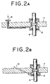
- the molecular oxygen-containing gas is preferred to be supplied into the thin-film type evaporating device through a molecular oxygen-containing gas supplying pipe (14) or a molecular oxygen-containing gas inlet (13) as illustrated in Fig. 2.
- the site for the supply of this sort is preferred to fall in the periphery part of a mechanical seal (8) of the stirring rotary shaft (4) in the device.
- the mechanical seal (8) is one kind of contrivance for proofing the stirring rotary shaft (4) against leakage. Since it prevents the leakage by establishing contact between the ring rotating in concert with the shaft and the stationary ring and causing the rings to slide against each other, it produces a nearly perfect airtight watertight closure. Since the interior of the thin-film type evaporating device constantly remains in a heated state and tends to induce adhesion of the distillate component and polymerization thereof, the eventual adhesion of the polymer interferes with smooth rotation of the rotary shaft. By supplying the molecular oxygen-containing gas via the periphery part of the mechanical seal (8), therefore, it is made possible to inhibit the polymerization liable to occur in the portion of the mechanical seal (8).
- the molecular oxygen-containing gas is supplied through the molecular oxygen-containing gas supplying pipe (14) which is disposed in the mechanical seal fixing plate (7) as illustrated in Fig. 1, therefore, the gas so supplied prevents the polymerization tending to occur in the periphery part of the mechanical seal (8), though the periphery part mentioned above constitutes itself the site for the presence of the vapor gas of the heated easily polymerizable substance and tends to induce polymerization.
- Fig. 2A illustrates one mode of providing the pipe (14) in the mechanical seal fixing plate (7) and Fig. 2B illustrates one mode of disposing the supplying inlet (13).
- the mode of Fig. 2A is furnished with the molecular oxygen-containing gas supplying pipe (14) piercing the mechanical seal fixing plate (7) and reaching the periphery part of the mechanical seal (8).
- the mode of Fig. 2B is not furnished with such a pipe but is provided with the supplying inlet (13) piercing the mechanical seal fixing plate (7) and serving the purpose of supplying the molecular oxygen-containing gas to the periphery part of the mechanical seal (8).
- the molecular oxygen-containing gas from an external source is supplied to the neighborhood of the mechanical seal (8) in the device and the gas so supplied is enabled to prevent polymerization from occurring in the mechanical seal part.
- the number of pipe (14) and supplying inlet (13) does not need to be limited to one but may be two or more as occasion demands.
- the device may be provided with the supply inlet (13) and the pipe (14) simultaneously.
- the pipe (1) is at an advantage in allowing the device to be manufactured easily and the supplying inlet (13) is at an advantage in inhibiting adhesion of the polymer resulting from the polymerization of the easily polymerizable substance because the pipes laid in the mechanical seal fixing plate (7) have no undulating part.
- the piping member may use an ordinary material which is generally used in the thin-film type evaporating device.
- the destination of the supply of the molecular oxygen-containing gas does not need to be limited to the periphery part of the mechanical seal (8) mentioned above.
- the known thin-film type evaporating device may be cited which effects the supply of the easily polymerizable substance to itself for the purpose of evaporation therein by means of the centrifugal force of the stirring rotary shaft.
- This thin-film type evaporating device is provided somewhere in the evaporating part (6) thereof with the molecular oxygen-containing gas supplying inlet (13) or the molecular oxygen-containing gas supplying pipe (14). Further, as illustrated in Fig.
- this invention designates the portion of the interior of the thin-film type evaporating device possessing the evaporating heating surface (3) as the evaporating part (6), designates the portion forming the terminal part of the evaporating part (6) and extending to the discharge outlet (10) for the extracted liquid as the liquid receiving part (12), and includes the liquid receiving part (12) in part of the evaporating part (6).
- the thin-film type evaporating device which is possessed of the liquid receiving part (12) as part of the evaporating part (6) is capable of supplying the molecular oxygen-containing gas to the liquid receiving part (12).
- the liquid receiving part (12) which has the molecular oxygen-containing gas supplying pipe pierce the liquid receiving part (12) and reach the interior thereof as illustrated in Fig. 3B may be cited.
- the liquid receiving part which is not provided with such a pipe but is provided with the molecular oxygen-containing gas supplying inlet (13) the liquid receiving part (12) which has the supplying inlet (12) for supply of a molecular oxygen-containing gas penetrate through the liquid receiving part (12) as illustrated in Fig. 3A may be cited.
- the supply of the molecular oxygen-containing gas by the molecular oxygen-containing gas supplying pipe (13) to the central part of the liquid receiving part (12) permits the gas to be easily mixed with the distillate component.
- the supplying inlet (13) or the pipe (14) may exist anywhere in the liquid receiving part (12) and is not discriminated on account of location or even quantity.
- the liquid receiving part (12) is possibly provided on the outside thereof with a heating part with the object of heating the extracted liquid.
- the supplying inlet (13) or the pipe (14) be disposed anywhere other than the heating part.
- the quantity of the pipe (13) does not need to be limited to one but may be two or more.
- the gas supplying inlet (13) and the gas pipe (14), when necessary, may be simultaneously provided.
- the pipe (13) is preferred to reach in proximity of the central of the liquid receiving part (12).
- the device which is provided in the periphery part of the mechanical seal (8) with the molecular oxygen-containing gas supplying pipe (14) or the supplying inlet (13) may be additionally provided in the liquid receiving part (12) with the supplying pipe (14) or the supplying inlet (13).
- the piping member may use a material generally used in the thin-film type evaporating device.
- the extracted liquid discharge outlet (10) may be supplied with either the extracted liquid or a solution having lower viscosity than the extracted liquid.
- this viscosity itself lowers the flow speed of the extracted liquid, suffers the extracted liquid to stagnate easily in the outlet, and renders difficult the discharge of the extracted liquid from the thin-film type evaporating device.
- the solution produced by subjecting the extracted liquid to a specific treatment may be used as the extracted liquid.
- a solution from some other source which has viscosity equal to or higher than the viscosity of the extracted liquid may be used when necessary.
- the evaporating part (6) includes as part thereof the liquid receiving part (12) which is directed from the lower terminal part of the evaporating heating surface (3) toward the extracted liquid discharge outlet (10).
- the supply of the extracted liquid to the discharge outlet (10) in the thin-film type evaporating device is accomplished by circulating the extracted liquid from the extracted liquid supplying inlet (10) of the liquid receiving part (12), optionally through the external pipe (11) connected to the supplying inlet (10), to the liquid receiving part (12).
- This pipe (11) is convenient in respect that it is capable of continuously supplying the extracted liquid to a specific place.
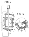
- the pipe (11) mentioned above assumes a structure of circulating through the extracted liquid discharging outlet (10) and the liquid receiving part (12) as illustrated in Fig. 1.
- the method for supplying the solution mentioned above does not need to be limited to the use of the pipe (11) mentioned above but may resort to the spray of the solution in the direction of the outlet (10).
- the device which is possessed of the molecular oxygen-containing gas supplying pipe (14) and the molecular oxygen-containing gas supplying inlet (13) mentioned above and is further provided in the liquid receiving part (12) thereof with the pipe (11) for supplying the extracted liquid or the solution having lower viscosity than the extracted liquid to the extracted liquid discharging outlet (10) and the extracted liquid supplying inlet (not shown) as illustrated in Fig. 1 may be cited.
- the solution supplying pipe (11) may be laid through anywhere in the liquid receiving part (12). The quantity of the pipe is irrelevant.
- the piping member may use a material generally used for the thin-film type evaporating device.
- the thin-film type evaporating device to be used in this invention does not necessarily require the stirring rotary shaft (4) built therein to be provided in the lower terminal part thereof with a bearing part.
- the vertical thin-film type evaporating device of a large size requires itself to be provided in the lower part thereof with a bearing part (15) as illustrated in Fig. 1 or requires an addition to the diameter of the shaft. Since the increase of the diameter of the shaft boosts the cost, the provision of the bearing (15) in the lower part is frequently resorted to.
- the bearing part (15) in the lower part often gives rise to a polymer.
- the extracted liquid or the solution having lower viscosity than the extracted liquid is supplied to the bearing part (15) through the bearing part extracted liquid supplying pipe (27) which is laid from outside the device toward the rotary shaft (4) as illustrated in Fig. 4.
- the gap between the stirring rotary shaft (4) and the bearing part (15) is liable to dry because it is held in a heated state.
- the thrust bearing in which the direction of the load to be borne coincides with the axial direction is liable to dry and induce polymerization of an easily polymerizable substance because it manifests a large load bearing force and suffers only small invasion of the extracted liquid.
- the rotational speed of the stirring rotary shaft (4) is consequently lowered.
- This invention therefore, prevents the bearing part (15) from inducing such adverse phenomena as clogging and polymerization by supplying the extracted liquid or the solution of low viscosity to the bearing part (15).
- the method for circulating the extracted liquid through such a bearing part (15) may comprise disposing the bearing part extracted liquid supplying pipe (27) as directed toward the bearing part (15) in the evaporating part and using this pipe for supply of the solution. By spraying the solution in the direction of the bearing part (15), it may be made possible to prevent the surface from drying and preclude the occurrence of the drying and polymerization.
- the bearing part extracted liquid supplying pipe (27) is not provided but the bearing part (15) is provided in advance with the pipe for supplying lubricating oil thereto, for example, the solution may be supplied through this pipe.
- the thin-film type evaporating device is enabled to exalt the effect thereof further by imparting surface roughness, Ry, specified in JIS (Japanese Industrial Standard) B 0601 (-1994), of not more than 12.5, preferably not more than 3.2, to part or whole of the surface of the thin-film type evaporating device which is exposed to an easily polymerizable substance.
- Ry surface roughness
- JIS Japanese Industrial Standard
- B 0601 Japanese Industrial Standard
- the buffing is a method of polishing which is mainly adopted for obtaining a smooth surface or a glossy surface and is known in such types as coarse buffing with a stationary abradant, medium buffing with a semisolid or free abradant, and finishing buffing.
- the buffing may be effected by using such flexible materials as leather and cloth and oily agents, non-oily agents, and spray grade agents containing tripolysilicate stone, chromium oxide, silicon carbide, fused alumina, calcined alumina, and chromium oxide as an abradant.
- the electrolytic polishing is a method for smoothing a metallic surface by the action of dissolving.
- the material for the contact surface is iron or steel
- perchloric acid solutions, sulfuric acid solutions, phosphoric acid solutions, and sulfuric acid-phosphoric acid solutions may be used for the electrolytic abrasion. Since iron and steel have their textures greatly vary with not only the difference in composition but also the difference in the degree of heat treatment and machining, the abradants mentioned above may be properly selected to suit the surface of contact to be involved.
- the quantity of acetic anhydride generally added to the perchloric acid type electrolyte, the electrolyzing temperature, the current density, the voltage, the electrolyzing time, etc., therefore, may be properly selected to suit the material of iron and steel.
- the mechanical polishing may be followed by an electrolytic polishing.
- the contact surface of the easily polymerizable substance ought to be construed as embracing the extracted liquid as an easily polymerizable substance. It is permissible to use the extracted liquid cyclically as the feed raw material.
- the extracted liquid outlet (10) is counted among such surfaces for contact with the easily polymerizable substance as described above.
- the welded part is preferred to be chamfered.
- an unevenness is present on the surface exposed to an easily polymerizable substance, it forms the cause for stagnation of the easily polymerizable substance and consequent adhesion of a polymer as described above.
- a corner part is formed in the part for connecting the outlet (10) to the liquid receiving part (12), the polymer is liable to adhere to the corner part. Further, the corner part obstructs the discharge of the extracted liquid.
- the chamfered welded part is preferred to be given a surface roughness, Ry specified in JIS B 0601 (-1994), of not more than 12.5, particularly not more than 3.2.
- the thin-film type evaporating device to be used in the present invention does not need to discriminate the construction thereof between the horizontal type and the vertical type.
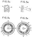
- the vertical thin-film type evaporating device is preferred to have the wiper (18) illustrated in Fig. 5B fixed to a rotor (17) through a variable vane supporting rod (19).
- the wiper (18) is generally fixed to the periphery part of the rotor (17) connected to beams projected radially from the stirring rotary shaft (4) and this wiper (18) serves the purpose of forming a thin film on the evaporating heating surface (3).
- the surface pressure of the wiper (18) is preferred to be adjusted by means of the movable vane supporting rod (19).
- variable vane supporting rod (19) The reason for using the variable vane supporting rod (19) is as follows. Specifically, for the adjustment of the wiper pressure, the method which relies on the centrifugal force and the method which relies on the pressure of the variable vane are available. In the case of the method which effects the adjustment by the centrifugal force through the medium of a wiper supporting metal (20) illustrated in Fig. 5A, there are times when the polymer adheres to the wiper (18). The wiper (18) functions to prevent the liquid under treatment from spattering and, at the same times, scrape and push down highly viscous liquid adhering to the surface.
- Fig. 5C which is cross sections taken through the line b-b in Fig. 1 compare the case of effecting the adjustment by the centrifugal force through the wiper supporting metal (20) of the wiper (18) and the case of effecting the adjustment by the variable vane supporting rod (19) respectively in terms of the state of attachment of wiper.
- this invention prefers the so-called cone angle, i.e. the angle between the generating lines of the cone, to be in the range of 40 - 70°, particularly in the range of 50 - 70°. If this angle exceeds 70°, the excess will be at a disadvantage in rendering the discharge of the highly viscous substance from the thin-film type evaporating device difficult. If the angle is less than 40°, the shortage will be at a disadvantage in requiring elongation of the lower axial part.
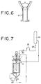
- Fig. 6 depicts a cone angle (a). This conical part is equivalent to the liquid receiving part (12) mentioned above.
- This invention is characterized by circulating the extracted liquid mentioned above to the raw material supplying inlet (1) thereby adjusting the quantity of the wetting liquid in the range of 0.02 - 2 m 3 /mHr. It, therefore, is characterized also by the constant presence of a solution in the part forming the cone mentioned above.
- This solution gains in viscosity in accordance as the evaporating heating surface shifts and the speed of discharge of the solution is lowered particularly in the neighborhood of the cone in consequence of the rise of the viscosity. Further, on the evaporating heating surface (3), the thin film of concentrated liquid is pushed, spread, and discharged in the direction of the outlet by the advancing force of the continuously supplied liquid and the centrifugal action of the liquid distributing plate (5).
- the extracted liquid is liable to stagnate in consequence of the rise of viscosity because such centrifugal force is absent.
- the method of this invention in the vertical thin-film type evaporating device which forms at the lower end thereof a cone converging from the lower terminal part of the device toward the extracted liquid outlet, prefers the angle formed between the generating line of the cone, to be in the range of 40 - 70°.
- the device which is possessed of such an angle cone is allowed to be provided with such supplying pipes as the molecular oxygen-containing gas supplying inlet and the discharge outlet for the liquid receiving part simultaneously.
- the downward gradient of the evaporating heating surface mentioned above is required to be not less than 1/200, preferably to be in the range of 1/200 - 1/10, and particularly preferably to be in the range of 1/100 - 1/10.
- the rise of the condensate liquid in concentration occurs in the same manner as in the vertical thin-wall type evaporating device as mentioned above. The impartation of the gradient mentioned above, therefore, results in preventing the easily polymerizable substance from stagnating in the interior of the evaporating device.
- the method of this invention is characterized by cyclically using at least part of the extracted liquid in the thin-film type evaporating device or supplying a solution having lower viscosity than the extracted liquid to the raw material supplying inlet (1).
- the extracted liquid may be temporarily stored in a storage tank (29) as illustrated in Fig. 7 and this storage tank may be utilized for the cyclic use mentioned above. It is further allowable to subject the extracted liquid in the storage tank (29) to a specific treatment such as thermal decomposition and thereafter put the treated liquid to cyclic use. Even when the extracted liquid is unusable in its unmodified form, the storage tank (29) is capable of adapting the liquid fit for cyclic use by giving it the treatment mentioned above.
- the effective utilization of the raw material can be materialized by using the storage tank (29) as a vessel for thermal decomposition and consequently decomposing the dimer and converting it into acrylic acid as a finished product.
- the temperature condition of the vessel for thermal decomposition may be properly selected to suit the characteristic properties of the easily polymerizable substance and the high-boiling substance contained therein.
- the solution which has been used therein is destined to form the extracted liquid from the outlet (10) mentioned above.
- the solution supplied as described above is to be included in the extracted liquid.
- This invention permits the liquid extracted from the recovering column disposed in the upper part of the thin-film type evaporating device to be used as the raw material for feeding.
- the use of the thin-film type evaporating device as the re-boiler for the extracted liquid from the acrylic acid recovering column corresponds itself to the case.
- the thin-film type evaporating device allows only a brief retention time, it is important that the device be fed with the raw material supplying liquid constantly in a fixed amount. If the raw material cannot be supplied in the fixed amount, the operation will be deprived of stability and the device will encounter such troubles as formation of polymer.
- This invention puts the liquid extracted from the liquid receiving part (12) to cyclic use also with the object of ensuring stable supply of the raw material. When the liquid extracted from the recovering column (22) is used as the raw material for feeding as mentioned above, there arises the possibility that the supply of the raw material in a fixed amount will not be accomplished.
- This failure may be logically explained by a supposition that a gas leaks into a line (23) starting from the recovering column (22) and returning to the thin-film type evaporating device and the ascent of this gas compels the liquid extracted from the recovering column to flow back.
- This invention contemplates easily and stably supplying the raw material by sealing the pipe with the liquid extracted from the recovering column as illustrated in Fig. 7 or by supplying the liquid extracted from the recovering column under pressure to the thin-film type evaporating device.
- the sealing part (23) using the liquid extracted from the recovering column (22) is disposed in part of the pipe which interconnects the extracted liquid outlet of the recovering column (22) and the thin-film type evaporating device.
- Such a liquid sealing part can be attained by disposing a projecting part arising from below the bottom part of the recovering column and reaching above the raw material supplying part of the thin-film type evaporating device in one part of the pipe interconnecting the extracted liquid outlet of the recovering column (22) and the thin-film type evaporating device and disposing in the projecting part a liquid reservoir to be filled with the liquid extracted from the recovering column (22).
- a projecting part arising from below the bottom part of the recovering column and reaching above the raw material supplying part of the thin-film type evaporating device in one part of the pipe interconnecting the extracted liquid outlet of the recovering column (22) and the thin-film type evaporating device and disposing in the projecting part a liquid reservoir to be filled with the liquid extracted from the recovering column (22).
- the supply of the liquid extracted from the recovering column under pressure to the thin-film type evaporating device as mentioned above may be fulfilled by furnishing the recovering column with a liquid level indicator capable of fixing the position (25, for example) of the liquid level of the bottoms in the recovery column at a fixed position in the recovering column (22) and, at the same time, disposing a pressure device in a part of the pipe interconnecting the outlet for the bottoms and the thin-film type evaporating device, and forcing the liquid extracted from the recovering column (22) under pressure to the thin-film type evaporating device.
- This invention particularly prefers the supply of the raw material to the thin-film type evaporating device to be implemented by forcing the extracted liquid under pressure. The reason for this preference is that the supply effected in this mode also allows a decrease in the retention time of the easily polymerizable substance within the recovering column.
- the recovering column (22) which is connected to the thin-film evaporating device does not need to set any limit on such factors as the theoretical number of steps, the diameter of the recovering column, the choice as to the use of a filler, and the kind of the filler, if used at all.
- the liquid extracted from the recovering column is only required to contain an easily polymerizable substance.
- a vertical thin-film type evaporating device was used which measured 1500 mm in inside diameter, used an evaporating heating surface with a surface roughness, Ry, of 3.2 and a wiper fixed by the pressure of a movable vane, and incorporated therein a cone having an angle of 50°, with a molecular oxygen supplying inlet provided in the periphery part of a mechanical seal and the welded part for the extracted liquid outlet chamfered.
- a solution containing 80 wt. % of 2-ethylhexyl acrylate and 1 wt. % of acrylic acid was through in the thin-film type evaporating device at a rate of 1.8 m 3 /Hr.
- the liquid extracted from the thin-film type evaporating device was introduced into storage tank and part of the liquid extracted from the storage tank was circulated to the thin-film type evaporating device.
- the molecular oxygen-containing gas was supplied to the thin-film type evaporating device at a rate of 2.6 Nm 3 /Hr.
- the temperature of the heating face was adjusted in the range of 110 - 130°C and the pressure was at 10 Torrs.
- the quantity of the liquid circulated from the storage tank to the thin-film type evaporating device was set at 3.8 m 3 /Hr so as to fix the quantity of the wetting liquid per unit length relative to the quantity of the liquid extracted from the bottoms of the thin-film type evaporating device at 0.9 m 3 /mHr.
- the quantity of the liquid extracted from the lower part of the thin-film type evaporating device was 4.1 m 3 /Hr, the portion 0.3 m 3 /Hr of which was discarded as waste liquid.
- An operation of the thin-film type evaporating device was performed by following the procedure of Example 1 while omitting the circulation of the liquid from the storage tank to the thin-film type evaporating device and changing the quantity of the wetting liquid per unit length relative to the quantity of the liquid extracted from the lower part of the thin-film type evaporating device to 0.01 m 3 /mHr.
- a recovering column was disposed in the upper part of a thin-film type evaporating device and the liquid extracted from the recovering column was further used as the raw material for feeding.
- a projecting part was formed in a pipe rising from below the bottom part of the recovering column and reaching above the raw material supplying part of the thin-film type evaporating device to provide a liquid seal.
- a distillation column measuring 1300 mm in inside diameter and incorporating therein 10 stepped sieve trays of stainless steel (SUS 316). Through the top of the column kept under pressure of 30 Torrs and at a temperature of 58°C, the raw material was supplied.
- the vertical thin-film type evaporating device used herein measured 1500 mm in inside diameter, used an evaporating heating surface with a surface roughness, Ry, of 3.2 and a wiper fixed by the pressure of a movable vane, and incorporated therein a cone having an angle of 50°, with a molecular oxygen supplying inlet provided in the periphery part of a mechanical seal and the welded part for the extracted liquid outlet chamfered
- the quantity of the liquid circulated from the storage tank to the thin-film type evaporating device was set at 3.4 m 3 /Hr so as to fix the quantity of the wetting liquid per unit length relative to the quantity of the liquid extracted from the bottoms of the thin-film type evaporating device at 0.8 m 3 /mHr.
- the quantity of the liquid extracted from the lower part of the thin-film type evaporating device was 4.0 m 3 /Hr, the portion 0.6 m 3 /Hr of which was discarded as waste liquid
- Example 2 An operation was performed by following the procedure of Example 2 while omitting the disposition of a projecting part in a pipe rising from below the bottom part of the recovering column and reaching above the raw material supplying part of the thin-film type evaporating device thereby avoiding the provision of a liquid seal, the raw material could not be supplied in a fixed quantity and the thin-film type evaporating device suffered formation of polymer therein. Thus, the operation had to be discontinued in two months.
Landscapes
- Chemical & Material Sciences (AREA)
- Chemical Kinetics & Catalysis (AREA)
- Vaporization, Distillation, Condensation, Sublimation, And Cold Traps (AREA)
- Organic Low-Molecular-Weight Compounds And Preparation Thereof (AREA)
Applications Claiming Priority (2)
| Application Number | Priority Date | Filing Date | Title |
|---|---|---|---|
| JP11699199 | 1999-04-23 | ||
| JP11699199A JP4143218B2 (ja) | 1999-04-23 | 1999-04-23 | 薄膜式蒸発装置における重合防止方法および薄膜式蒸発装置 |
Publications (3)
| Publication Number | Publication Date |
|---|---|
| EP1046416A2 true EP1046416A2 (de) | 2000-10-25 |
| EP1046416A3 EP1046416A3 (de) | 2001-01-03 |
| EP1046416B1 EP1046416B1 (de) | 2006-09-20 |
Family
ID=14700781
Family Applications (1)
| Application Number | Title | Priority Date | Filing Date |
|---|---|---|---|
| EP00302853A Expired - Lifetime EP1046416B1 (de) | 1999-04-23 | 2000-04-04 | Verfahren zum Verhindern von Polymerisation in Dünnschichtverdampfern |
Country Status (6)
| Country | Link |
|---|---|
| US (1) | US6627047B1 (de) |
| EP (1) | EP1046416B1 (de) |
| JP (1) | JP4143218B2 (de) |
| CN (1) | CN1246060C (de) |
| BR (1) | BR0001748B1 (de) |
| MY (1) | MY120606A (de) |
Cited By (5)
| Publication number | Priority date | Publication date | Assignee | Title |
|---|---|---|---|---|
| WO2003045890A1 (fr) * | 2001-10-30 | 2003-06-05 | Mitsubishi Chemical Corporation | Procede de purification d'acide (meth)acrylique |
| WO2004050596A1 (de) * | 2002-11-29 | 2004-06-17 | Basf Aktiengesellschaft | Verfahren zur rektifikativen auftrennung von (meth)acrylmonomere enthaltenden flüssigkeiten in einer rektifikationskolonne |
| CN108325232A (zh) * | 2018-05-09 | 2018-07-27 | 安庆市鑫富化工有限责任公司 | 一种防止物料聚合新型再沸器 |
| CN112402996A (zh) * | 2020-10-21 | 2021-02-26 | 戴晓锋 | 一种化妆品用乳香提取物的提取浓缩装置 |
| DE102023107156A1 (de) | 2023-03-22 | 2024-09-26 | Röhm Gmbh | Verfahren zur verbesserten Aufarbeitung von Monomer-haltigen Abgasen |
Families Citing this family (20)
| Publication number | Priority date | Publication date | Assignee | Title |
|---|---|---|---|---|
| CN100402493C (zh) * | 2003-03-31 | 2008-07-16 | 科学与工业研究委员会 | 回收纯丙烯腈的方法 |
| FR2878257B1 (fr) | 2004-11-24 | 2007-01-12 | Usinor Sa | Procede de fabrication de toles d'acier austenitique, fer-carbone-manganese a tres hautes caracteristiques de resistance et d'allongement, et excellente homogeneite |
| US8157969B2 (en) * | 2006-06-01 | 2012-04-17 | Rohm And Haas Company | Method and apparatus for minimizing accumulation of polymer on process equipment, especially safety devices |
| JP4995645B2 (ja) * | 2007-06-11 | 2012-08-08 | 株式会社日本触媒 | 易重合性化合物含有液の蒸留方法 |
| US8858758B2 (en) * | 2010-07-21 | 2014-10-14 | Aquaback Technologies, Inc. | Distiller |
| WO2012173153A1 (ja) * | 2011-06-15 | 2012-12-20 | 旭硝子株式会社 | 含フッ素共重合体の製造方法 |
| DE102013222343A1 (de) * | 2013-11-04 | 2015-05-07 | Matthias Enzenhofer | Vorrichtung und Verfahren für den Kontakt einer Gasphase mit einem flüssigen Medium |
| JP6244259B2 (ja) * | 2014-05-07 | 2017-12-06 | 新日鉄住金化学株式会社 | 高純度ビスフェノールfの製造方法 |
| CN105879415A (zh) * | 2014-12-23 | 2016-08-24 | 江南大学 | 一种薄层化多折面蒸发器的制造方法 |
| US11173416B2 (en) * | 2019-03-29 | 2021-11-16 | Julian Alexander Bublies | Short-path evaporator |
| CN110711395B (zh) * | 2019-09-20 | 2021-06-22 | 陈哲 | 一种中央循环管式蒸发器 |
| JP7392980B2 (ja) * | 2019-12-20 | 2023-12-06 | 竹本油脂株式会社 | 水硬性組成物用添加剤の製造方法 |
| CN112774229A (zh) * | 2021-02-21 | 2021-05-11 | 徐浩 | 一种用于高浓度玉米浆蒸发浓缩的生产方法 |
| JP7805188B2 (ja) * | 2022-02-02 | 2026-01-23 | 株式会社トクヤマ | クロロシラン類の回収方法 |
| US20250263387A1 (en) * | 2022-03-25 | 2025-08-21 | Mitsubishi Gas Chemical Company, Inc. | Method for purifying (meth)acrylic acid monomer and/or (meth)acrylic acid ester monomer |
| TW202415434A (zh) | 2022-07-25 | 2024-04-16 | 日商神鋼環境舒立淨股份有限公司 | 液體濃縮方法及薄膜蒸發裝置 |
| WO2024084649A1 (ja) * | 2022-10-20 | 2024-04-25 | 日本ポリプロ株式会社 | 重合反応装置及びプロピレン系重合体の製造方法 |
| CN115676950B (zh) * | 2022-11-16 | 2025-07-01 | 安徽华塑股份有限公司 | 一种电石干法乙炔渣浆水回用工艺 |
| CN116889738A (zh) * | 2023-08-02 | 2023-10-17 | 邦丽达(福建)新材料股份有限公司 | 一种旋风精馏塔、丙烯酸脱重组分系统和提纯工艺 |
| CN120204748B (zh) * | 2025-05-28 | 2025-08-05 | 江西道仕化学有限公司 | 一种异丙基异氰酸酯生产制备用精馏装置 |
Family Cites Families (21)
| Publication number | Priority date | Publication date | Assignee | Title |
|---|---|---|---|---|
| NL176744B (nl) * | 1952-04-24 | Helopharm Petrik Co Kg | Werkwijze voor de bereiding van tegen orthostatische dysregulatie werkzame preparaten. | |
| GB1307582A (en) * | 1969-06-10 | 1973-02-21 | Rohm & Haas | Inhibition of polymerization of acrylic acids |
| CH509558A (de) * | 1969-06-11 | 1971-06-30 | Luwa Ag | Flüssigkeitsabscheider für Dünnschichtapparate |
| JPS53711B2 (de) * | 1973-01-16 | 1978-01-11 | ||
| DE2449780C3 (de) * | 1974-10-19 | 1987-01-22 | Basf Ag, 6700 Ludwigshafen | Verfahren zum Abtrennen schwer- oder nichtflüchtiger Nebenprodukte der Propylen- und/oder Acroleinoxidation von den für die Absorbtion der Acrylsäure aus den Reaktionsgasen verwendeten Lösungsmitteln |
| US4065346A (en) * | 1975-11-26 | 1977-12-27 | Ivan Frolovich Evkin | Roter thin-film evaporator |
| GB1588960A (en) * | 1976-12-10 | 1981-05-07 | Balfour & Co Ltd H | Evaporators particularly wiped film evaporators |
| FR2510420A1 (fr) * | 1979-11-23 | 1983-02-04 | Fives Cail Babcock | Evaporateur a flot descendant |
| FR2501348A1 (fr) * | 1981-03-09 | 1982-09-10 | Stein Industrie | Procede de vaporisation d'un liquide pur |
| IT1148117B (it) * | 1982-03-05 | 1986-11-26 | Medosan Ind Biochimi | Attivita'antiflogistica,analgesica,antipiretica,mucolitica e seda tiva della tosse dell'1 metil-5-p-tolilpirrol-2-acetato di 2'metossi-fenile |
| DE3338488A1 (de) * | 1982-10-29 | 1984-05-03 | Basf Ag, 6700 Ludwigshafen | Verfahren zur gewinnung von temperaturempfindlichen produkten durch thermisch schonende destillation mittels eines mit einer destillationskolonne verbundenen duennschichtverdampfers und eine anordnung zur durchfuehrung des verfahrens |
| US4674651A (en) * | 1985-11-15 | 1987-06-23 | Scidmore Fred A | Pill dispenser |
| JPH0653711B2 (ja) | 1986-02-24 | 1994-07-20 | 三井東圧化学株式会社 | アクリル酸またはメタクリル酸のアルキルアミノアルキルエステルの精製方法 |
| US5250151A (en) * | 1990-10-11 | 1993-10-05 | Joaquin Huercanos | Method of evaporating liquids |
| BR9508592A (pt) * | 1994-08-18 | 1997-12-23 | Ici Plc | Processo para preparar ésteres acrílicos refinados |
| US5632797A (en) * | 1994-12-30 | 1997-05-27 | Corning Incorporated | Method of providing vaporized halide-free, silicon-containing compounds |
| DE19501326A1 (de) * | 1995-01-18 | 1996-07-25 | Basf Ag | Verfahren der rektifikativen Abtrennung von (Meth)acrylsäure aus einem (Meth)acrylsäure als Hauptbestandteil und niedere Aldehyde als Nebenbestandteile enthaltenden Gemisch in einer aus Abtriebsteil und Verstärkerteil bestehenden Rektifiaktionskolonne |
| DE19539295A1 (de) * | 1995-10-23 | 1997-04-24 | Basf Ag | Verfahren zur kontinuierlichen destillativen Auftrennung von flüssigen Gemischen, die als Hauptbestandteil (Meth)acrylsäure enthalten |
| DE19711925B9 (de) | 1996-04-01 | 2008-04-17 | Mitsubishi Chemical Corp. | Verfahren zur Reinigung von N-Vinylformamid |
| DE19634614A1 (de) * | 1996-08-27 | 1998-03-05 | Basf Ag | Verfahren zur destillativen Abtrennung von Rein-(Meth)acrylsäure aus Gemischen, die im wesentlichen frei sind von Komponenten, deren Siedepunkt niedriger als der der (Meth)acrylsäure ist |
| JPH1112222A (ja) * | 1997-06-25 | 1999-01-19 | Nippon Shokubai Co Ltd | アクリル酸の回収方法 |
-
1999
- 1999-04-23 JP JP11699199A patent/JP4143218B2/ja not_active Expired - Lifetime
-
2000
- 2000-04-03 MY MYPI20001372A patent/MY120606A/en unknown
- 2000-04-04 EP EP00302853A patent/EP1046416B1/de not_active Expired - Lifetime
- 2000-04-21 US US09/556,754 patent/US6627047B1/en not_active Expired - Lifetime
- 2000-04-23 CN CN00118165.3A patent/CN1246060C/zh not_active Expired - Lifetime
- 2000-04-24 BR BRPI0001748-5A patent/BR0001748B1/pt not_active IP Right Cessation
Cited By (9)
| Publication number | Priority date | Publication date | Assignee | Title |
|---|---|---|---|---|
| WO2003045890A1 (fr) * | 2001-10-30 | 2003-06-05 | Mitsubishi Chemical Corporation | Procede de purification d'acide (meth)acrylique |
| US7265241B2 (en) | 2001-10-30 | 2007-09-04 | Mitsubishi Chemical Corporation | Method for purifying (meth)acrylic acid |
| US7414150B2 (en) | 2001-10-30 | 2008-08-19 | Mitsubishi Chemical Corporation | Method for purifying (meth)acrylic acid |
| WO2004050596A1 (de) * | 2002-11-29 | 2004-06-17 | Basf Aktiengesellschaft | Verfahren zur rektifikativen auftrennung von (meth)acrylmonomere enthaltenden flüssigkeiten in einer rektifikationskolonne |
| US7300555B2 (en) | 2002-11-29 | 2007-11-27 | Basf Aktiengesellschaft | Method for the rectifying separation of liquids containing (meth)acrylic monomers in a rectification column |
| CN108325232A (zh) * | 2018-05-09 | 2018-07-27 | 安庆市鑫富化工有限责任公司 | 一种防止物料聚合新型再沸器 |
| CN108325232B (zh) * | 2018-05-09 | 2023-12-22 | 安庆市鑫富化工有限责任公司 | 一种防止物料聚合新型再沸器 |
| CN112402996A (zh) * | 2020-10-21 | 2021-02-26 | 戴晓锋 | 一种化妆品用乳香提取物的提取浓缩装置 |
| DE102023107156A1 (de) | 2023-03-22 | 2024-09-26 | Röhm Gmbh | Verfahren zur verbesserten Aufarbeitung von Monomer-haltigen Abgasen |
Also Published As
| Publication number | Publication date |
|---|---|
| EP1046416B1 (de) | 2006-09-20 |
| BR0001748B1 (pt) | 2010-04-06 |
| MY120606A (en) | 2005-11-30 |
| JP2000300901A (ja) | 2000-10-31 |
| BR0001748A (pt) | 2001-01-23 |
| US6627047B1 (en) | 2003-09-30 |
| EP1046416A3 (de) | 2001-01-03 |
| CN1246060C (zh) | 2006-03-22 |
| CN1273136A (zh) | 2000-11-15 |
| JP4143218B2 (ja) | 2008-09-03 |
Similar Documents
| Publication | Publication Date | Title |
|---|---|---|
| US6627047B1 (en) | Method for preventing polymerization in thin-film type evaporating device | |
| KR100423210B1 (ko) | 쉽게 중합 가능한 화합물의 중합 억제 방법 | |
| US7393436B2 (en) | Thermal separating process for removing at least one stream containing enriched (meth) acrylic monomers | |
| CN1262810C (zh) | 管壳式换热器以及在管壳式换热器内抑制聚合反应的方法 | |
| US7282118B2 (en) | Method for production of easily polymerizable substance and purification apparatus | |
| US20150158011A1 (en) | Thermal separation process | |
| JP5627609B2 (ja) | 目的化合物を母液中の目的化合物の結晶懸濁液から精製分離するための方法 | |
| US4369097A (en) | Method and apparatus of distillation for readily polymerizable liquid | |
| JP2000254403A (ja) | 蒸気分散装置を有する精製装置 | |
| US7253314B2 (en) | Method for refining easily polymerizable matter-containing substance and apparatus therefor | |
| US4323431A (en) | Purification of compounds having high melting point | |
| US5419814A (en) | Thin layer liquid film type evaporator | |
| US6443170B1 (en) | Cleaning apparatus for removing residues | |
| GB2176209A (en) | Condensing zinc vapour | |
| JP4068839B2 (ja) | 易重合性物質の貯蔵タンク | |
| WO2005046860A1 (ja) | 易重合性化合物用の容器 | |
| JP2006175378A (ja) | 発泡性溶液の蒸発装置及び蒸発方法 | |
| US3923839A (en) | Method of treating the residues from the distillation of phthalic anhydride | |
| JP2004009006A (ja) | 加熱装置 |
Legal Events
| Date | Code | Title | Description |
|---|---|---|---|
| PUAI | Public reference made under article 153(3) epc to a published international application that has entered the european phase |
Free format text: ORIGINAL CODE: 0009012 |
|
| AK | Designated contracting states |
Kind code of ref document: A2 Designated state(s): BE |
|
| AX | Request for extension of the european patent |
Free format text: AL;LT;LV;MK;RO;SI |
|
| PUAL | Search report despatched |
Free format text: ORIGINAL CODE: 0009013 |
|
| AK | Designated contracting states |
Kind code of ref document: A3 Designated state(s): AT BE CH CY DE DK ES FI FR GB GR IE IT LI LU MC NL PT SE |
|
| AX | Request for extension of the european patent |
Free format text: AL;LT;LV;MK;RO;SI |
|
| RIC1 | Information provided on ipc code assigned before grant |
Free format text: 7B 01D 1/22 A, 7B 01D 1/06 B, 7B 01D 3/14 B |
|
| 17P | Request for examination filed |
Effective date: 20010530 |
|
| AKX | Designation fees paid |
Free format text: BE |
|
| REG | Reference to a national code |
Ref country code: DE Ref legal event code: 8566 |
|
| 17Q | First examination report despatched |
Effective date: 20030804 |
|
| GRAP | Despatch of communication of intention to grant a patent |
Free format text: ORIGINAL CODE: EPIDOSNIGR1 |
|
| GRAS | Grant fee paid |
Free format text: ORIGINAL CODE: EPIDOSNIGR3 |
|
| GRAA | (expected) grant |
Free format text: ORIGINAL CODE: 0009210 |
|
| AK | Designated contracting states |
Kind code of ref document: B1 Designated state(s): BE |
|
| PLBE | No opposition filed within time limit |
Free format text: ORIGINAL CODE: 0009261 |
|
| STAA | Information on the status of an ep patent application or granted ep patent |
Free format text: STATUS: NO OPPOSITION FILED WITHIN TIME LIMIT |
|
| 26N | No opposition filed |
Effective date: 20070621 |
|
| PGFP | Annual fee paid to national office [announced via postgrant information from national office to epo] |
Ref country code: BE Payment date: 20160314 Year of fee payment: 17 |
|
| REG | Reference to a national code |
Ref country code: BE Ref legal event code: MM Effective date: 20170430 |
|
| PG25 | Lapsed in a contracting state [announced via postgrant information from national office to epo] |
Ref country code: BE Free format text: LAPSE BECAUSE OF NON-PAYMENT OF DUE FEES Effective date: 20170430 |