EP1046564A2 - Bremssystem für einen Zug - Google Patents
Bremssystem für einen Zug Download PDFInfo
- Publication number
- EP1046564A2 EP1046564A2 EP00108362A EP00108362A EP1046564A2 EP 1046564 A2 EP1046564 A2 EP 1046564A2 EP 00108362 A EP00108362 A EP 00108362A EP 00108362 A EP00108362 A EP 00108362A EP 1046564 A2 EP1046564 A2 EP 1046564A2
- Authority
- EP
- European Patent Office
- Prior art keywords
- train
- braking
- vehicle
- bus
- parts
- Prior art date
- Legal status (The legal status is an assumption and is not a legal conclusion. Google has not performed a legal analysis and makes no representation as to the accuracy of the status listed.)
- Granted
Links
- 238000004891 communication Methods 0.000 claims abstract description 11
- 238000000926 separation method Methods 0.000 claims description 25
- 230000001960 triggered effect Effects 0.000 claims description 7
- 230000003137 locomotive effect Effects 0.000 description 9
- 239000011159 matrix material Substances 0.000 description 4
- 238000012360 testing method Methods 0.000 description 4
- 206010012411 Derailment Diseases 0.000 description 3
- 238000012545 processing Methods 0.000 description 3
- 230000008878 coupling Effects 0.000 description 2
- 238000010168 coupling process Methods 0.000 description 2
- 238000005859 coupling reaction Methods 0.000 description 2
- 238000010586 diagram Methods 0.000 description 2
- 230000001133 acceleration Effects 0.000 description 1
- 230000000903 blocking effect Effects 0.000 description 1
- 238000013461 design Methods 0.000 description 1
- 230000003628 erosive effect Effects 0.000 description 1
- 238000011156 evaluation Methods 0.000 description 1
- 238000012549 training Methods 0.000 description 1
- 238000009423 ventilation Methods 0.000 description 1
Images

Classifications
-
- B—PERFORMING OPERATIONS; TRANSPORTING
- B60—VEHICLES IN GENERAL
- B60T—VEHICLE BRAKE CONTROL SYSTEMS OR PARTS THEREOF; BRAKE CONTROL SYSTEMS OR PARTS THEREOF, IN GENERAL; ARRANGEMENT OF BRAKING ELEMENTS ON VEHICLES IN GENERAL; PORTABLE DEVICES FOR PREVENTING UNWANTED MOVEMENT OF VEHICLES; VEHICLE MODIFICATIONS TO FACILITATE COOLING OF BRAKES
- B60T13/00—Transmitting braking action from initiating means to ultimate brake actuator with power assistance or drive; Brake systems incorporating such transmitting means, e.g. air-pressure brake systems
- B60T13/10—Transmitting braking action from initiating means to ultimate brake actuator with power assistance or drive; Brake systems incorporating such transmitting means, e.g. air-pressure brake systems with fluid assistance, drive, or release
- B60T13/66—Electrical control in fluid-pressure brake systems
- B60T13/665—Electrical control in fluid-pressure brake systems the systems being specially adapted for transferring two or more command signals, e.g. railway systems
-
- B—PERFORMING OPERATIONS; TRANSPORTING
- B60—VEHICLES IN GENERAL
- B60T—VEHICLE BRAKE CONTROL SYSTEMS OR PARTS THEREOF; BRAKE CONTROL SYSTEMS OR PARTS THEREOF, IN GENERAL; ARRANGEMENT OF BRAKING ELEMENTS ON VEHICLES IN GENERAL; PORTABLE DEVICES FOR PREVENTING UNWANTED MOVEMENT OF VEHICLES; VEHICLE MODIFICATIONS TO FACILITATE COOLING OF BRAKES
- B60T17/00—Component parts, details, or accessories of power brake systems not covered by groups B60T8/00, B60T13/00 or B60T15/00, or presenting other characteristic features
- B60T17/18—Safety devices; Monitoring
- B60T17/22—Devices for monitoring or checking brake systems; Signal devices
- B60T17/228—Devices for monitoring or checking brake systems; Signal devices for railway vehicles
Definitions
- the invention relates to a braking system for a train with those mentioned in the preamble of claim 1 Characteristics.
- Braking systems for trains are known.
- Air brake systems known where via a main air duct running through the entire train arranged on the individual vehicles of the train pneumatic brake devices can be controlled are.
- the braking devices are loosened Condition or in braking condition. If you want to slow down a train driver can use a so-called Driver brake valve the pressure level in the Lower the main air line so that the brakes apply.
- Driver brake valve the pressure level in the Lower the main air line so that the brakes apply.
- an unwanted train separation for example by failure of a mechanical coupling between Vehicles of the train become the main air duct interrupted (torn off) so that an immediately occurring Pressure drop in the main air line for application of the pneumatic braking devices.
- braking systems are known in which the entire length of the train an electrical control line is switched via the pneumatic braking devices triggering solenoid valves can be controlled. When a voltage is applied across the electrical Control line, the braking devices are released. At a voltage drop, either intentionally over a Train driver or unintentionally with a train separation, solve the solenoid valves from the braking devices, so that emergency braking (rapid braking) is also initiated becomes. Here the same high mechanical Signs of wear.
- Actuators System components are a master or assigned to a master bus via a gateway is coupled to the train bus.
- Such setpoint generating System components are for example in Locomotives, control cars or the like arranged.
- System components converting the manipulated value can each via a slave bus and a gateway or via a vehicle control unit is coupled to the train bus his.
- the system components that implement the manipulated value usually every vehicle (exception measuring vehicle or the like) of the train.
- Actuators System components are, for example, drive controls, Brake controls or the like for active Leading the train.
- System components converting the manipulated variable are, for example, drives, brakes or the like, which correspond to those above the value generator System components respond to given commands.
- System components For clear control over the data communication system to ensure one Vehicle of the train - usually a locomotive or control car - assigned a master function. All other vehicles on the train receive one Slave function.
- the invention has for its object a braking system to create the generic type with in a simple manner a safe and wear-resistant as possible Braking in case of unwanted train separation is feasible.
- this object is achieved by a braking system solved with the features mentioned in claim 1.
- a braking system solved with the features mentioned in claim 1.
- Take over function for the braking system advantageously achieved that - only in the event of unwanted Train separation - every single part of the train former train at least for the braking function has activated control-generating system components.
- Such a design of the braking system particularly advantageously possible to brake the individual train parts by dynamically acting service brake devices perform.
- auxiliary master functions By the presence at least one setpoint-generating system component for the braking system in each of the train parts so-called auxiliary master functions are possible, so that a control of the service brake devices becomes possible.
- Full braking service braking
- Rapid braking force braking
- the compressed air braking devices excessive wear between the friction partners of the brake system.
- a first (front) Train part of the former train is braking hard, during the at least one further train part experiences rapid braking. This will be advantageous avoided that rear traction parts on front traction parts accumulate, since this with a higher braking acceleration be charged.
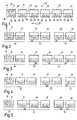
- FIG. 1 schematically shows a train 10.
- the train 10 comprises a locomotive 12 and five cars (hereinafter Vehicles) 14, 16, 18, 20 and 22. After others; Embodiments not shown can the configuration of the train 10 of course be chosen differently. For example fewer or more vehicles or more than one locomotive be put together in train 10.
- the vehicles of the train 10 are not shown in detail mechanical couplings connected together.
- a continuous air line can also be provided be about the pneumatic braking devices are controllable in a manner yet to be explained.
- Vehicles 12, 14, 16, 18, 20, 22 of train 10 are connected to each other via a train bus 24.
- the Train bus 24 can be, for example, a CAN bus, a radio bus or the like.
- the vehicles 12, 14, 16, 18, 20 each have an in-vehicle vehicle bus system 26, each via a gateway 28 is coupled to the train bus 24.
- the vehicle 22 owns a vehicle control unit 23 connected to the train bus 24 is coupled. Multiple vehicles can also be used a vehicle control unit 23 instead of the vehicle bus system 26 have.
- Vehicle control unit 23 To the vehicle bus systems 26 or that Vehicle control unit 23 are system components that convert control values 30 connected.
- the system components 30 can, for example, drive devices, Braking devices or the like. these are in any case, components that are received as a result Execute commands. Components can also do this be the information about operating conditions deliver. For the explanation of the exemplary embodiments it is assumed that the system components 30 is braking devices.
- the locomotive 12 has another vehicle bus system 32 through a gateway 34 to the train bus 24 is coupled.
- system components 36 generating primary control values are connected.
- the system components 36 are able to from specifications of a driver or one electronic control system commands to run the Turn to give 10.
- the System components 36 around facilities for giving Brake commands for the train 10 is.
- the train's data communication system 10 (train baptism) carried out. This takes care of that Vehicle bus system 32 a master function for the Train bus 24, while the vehicle bus systems 26 and or the vehicle control units 23 each take on a slave function. The exchange of the data or signals takes place via the gateways 34 or 28 or the vehicle control unit 23. For the function of the data communication system it is important that 10 only one vehicle bus system 32 has a master function active takes over. In the event of a brake command via the system components 36 appropriate brake commands generated and over the Train bus 24 the individual system component converting the manipulated variable 30 transmitted. These then lead braking through.
- This braking can, for example consist in that about individual, not shown Valves a defined ventilation of Brake cylinders of the pneumatic brake devices can be done in the respective vehicles. Further can also use eddy current brakes, for example can be controlled. An assumed direction of travel the train is accepted according to arrow 38.
- FIGS of the train 10 Different configurations are shown in FIGS of the train 10 shown that an assumed unwanted train separation could occur. Of course, other configurations are possible.
- the same parts as in Figure 1 are each with provided the same reference numerals and not again explained.
- the train part 40 from the motor vehicle 12 and the Carriage 14, the train part 42 from vehicles 16 and 18 and the train part 44 from the vehicles 20 and 22.
- the train part 40 consists of the locomotive 12 and the vehicle 14, the train part 42 from the Vehicle 16 and the train part 44 from vehicles 18, 20 and 22.
- FIG. 1 the train part 40 from the motor vehicle 12 and the Carriage 14
- the train part 42 from vehicles 16 and 18 and the train part 44 from the vehicles 20 and 22.
- the train part 40 consists of the locomotive 12 and the vehicle 14, the train part 42 from the Vehicle 16 and the train part 44 from vehicles 18, 20 and 22.
- the tension part 40 consists of the motor vehicle 12 and the vehicles 14 and 16, the train part 42 from the vehicles 18 and 20 and the Train part 44 consists of the vehicle 22.
- the train part 40 from the motor vehicle 12, the train part 42 from vehicles 14, 16 and 18 and the train part 44 from vehicles 20 and 22.
- FIG. 6 there is one Train division adopted by a slightly different one Initial configuration of the train 10 goes out.
- the locomotive 12 is arranged within the train network, so that the pulling part 40 from the vehicles 14, 16 and 18, the train part 42 from the locomotive 12 ' and the train part 44 consists of the vehicles 20 and 22.
- train part 40 In the train parts (train part 40 according to Figures 2 to 5, respectively Pull part 42 according to Figure 6) Braking by the master function within the Turn 10 vehicle bus system 32, so about the setpoint-generating system components 36.
- train parts In the train parts (train parts 42 and 44 according to FIG. 2 to 5, or train parts 40 and 44 according to the figure 6) Braking is performed by the slave vehicle bus systems 26 or the vehicle control unit 23, that in the direction of travel 38 at the top of each resulting train parts 42 and 44 (in Fig 6 tension member 40) is arranged.
- the train 10 is the determination of the vehicle order in the train set 10 a routine to be processed. This Vehicle sequence is available for all vehicle bus systems and Vehicle control units or those arranged thereon System components available as information.
- auxiliary master is assigned to the Vehicle bus system 26 or vehicle control system 23 of the vehicle in front of the individual train parts. This ensures that exactly one master function within the respective train parts - now auxiliary master function - via the data communication system, which is only available in parts to actively influence the Braking can take place.
- auxiliary masters control and regulate all to the respective train part 40, 42 or 44 associated system value-converting system components 30 that affect the braking devices.
- the brake control takes place in such a way that the preceding one Gebteil 40 full braking (service braking) experiences while the subsequent train parts 42, 44 experience an emergency stop.
- the rear train parts to stand faster and can therefore do not run onto the front part of the train.
- the gateways 28 and the vehicle control unit 23 have not shown in detail electronic components, such as microprocessors, Storage elements or the like, by means of which one intelligent signal processing or processing can be carried out. Part of signal processing is the query of information 46, 48, 50, 52 and 54.
- Information 46 includes that of the respective gateways 28 - as a result of the train separation - No signals from the master vehicle bus system 32 more to be received.
- Information 48 includes that from the last vehicle of train 10, here vehicle 22, no signal is received.
- This signal from the last vehicle on the train 10 serves as a so-called train final control and is per se via train bus 24 according to the polling cycle always available.
- the information 50 includes that an electrical led by the train 10 Power supply no longer provides on-board voltage.
- information 52 includes that no communication via train bus 24, that is Data exchange takes place.
- This information 46, 48, 50 and 52 logically become a switching matrix 56 fed so that at the output of the switching matrix 56 Signal 58 is present if a corresponding evaluation of information 46, 48, 50 or 52 is present.
- the Output signal 58 is fed to an AND gate 60.
- the information 54 At another input of the AND gate 60 is the information 54, which contains that the respective Vehicle is not a single locomotive 12.
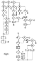
- FIG 8 shows a flowchart showing the query routine the switching matrix 56 in the gateways 28 and the vehicle control unit 23 illustrates.
- This Query routine is at predefinable time intervals continuously repeated and leads to the finding whether there is a train separation and in the event that There is a train separation which components of the respective Glasmaschine the auxiliary master function for the Brake control have to take over.
- In the schedule are the answers to the questions with 0 for "no" and 1 labeled "yes".
- query 62 is made as to whether the respective Component itself already the master function in the train 10 holds. If “yes”, the removal 64 takes place by means of the arrangement of the master within the train 10 is checked. The query 64 includes whether the number of the current master greater than 1 and less than the total number of vehicles on the train 10 is. If “no” follows query 66 with the question is whether the last vehicle of the train 10 respectively whose turn signal is heard. If query 66 is answered with "yes”, the Decision 4 ⁇ made, which implies that a Separation of the train 10 is not present. Will the query 66 answered with "no”, the removal follows 68, whether the running vehicle 2 is heard.
- Query 62 shows that gateway 28 or the vehicle control unit 23 does not itself have the master function question 80 whether the Master of train 10 is heard. If “yes”, the Query 82 whether the last vehicle or the train closing signal of train 10 is heard. At “No” the result is 1 ⁇ and the service braking 72 is carried out until braking 5 ⁇ . If query 82 is answered with “yes”, this will be Result 4 ⁇ determined, that is, there is none Train separation before.
- query 84 whether the last vehicle respectively heard the train closing signal of train 10 becomes. If “no” follows query 86, which includes whether an immediately preceding vehicle inside the train 10 is heard. The decision is made with "yes” 3 ⁇ , that is, the current gateway 28 respectively Vehicle control unit 23 does not take over Auxiliary master function in the respective train part. Will the Answered query 26 with “no”, the query follows 88, which includes whether the current vehicle following vehicle is heard. This question answered with "yes”, decision 2 ⁇ follows includes that the current gateway 28 or the vehicle control unit 23 the auxiliary master function takes over and a quick braking of the respective Train part until braking 5 ⁇ takes over.
- query 88 is answered with "no"
- it is done a self-test 90 the result of which gives 92 whether it is a single vehicle or not.
- the rapid braking 94 is triggered, which leads to braking 5 ⁇ .
- the query 96 takes place as to whether the respective Gateway 28 or vehicle control unit 23 a Receives energy supply. If the question is answered with “yes”, follows decision 4 ⁇ , that is, it there is no train separation. If the query 36 with Answered "no”, rapid braking 94 takes place for braking 5 ⁇ .
- Query 84 returns that the last vehicle or The connection signal is heard, the Cancel 98 whether the gateway 38 or that Vehicle control unit 23 itself in the last vehicle of the Turn 10 is. If “no" follows query 100, which determines whether an immediately preceding vehicle is heard. If query 100 results in “no”, the Action 2 ⁇ triggered, that is, the gateway 28 respectively the vehicle control unit 23 takes over Auxiliary master function and triggers the rapid braking for braking 5 ⁇ off. If query 100 is answered with "yes” answered, action 3 ⁇ is triggered, i.e. this gateway 28 or vehicle control unit 23 does not become an auxiliary master in the respective train part.
- Query 98 returns that the vehicle is the last vehicle of the train, the removal 102 follows, which includes whether the immediately preceding vehicle the train 10 is heard. If “yes” follows Action 3 ⁇ , that is, the respective gateway 28 or Vehicle control unit 23 does not become an auxiliary master. If the query 102 results in “no”, a occurs Self-test 104 with the result 106, which includes whether the respective vehicle is a single vehicle. At “yes”, rapid braking 94 takes place until braking 5 ⁇ . If “no”, the query 108 is made as to whether the respective vehicle receives an energy supply. At “yes” is the decision 4 ⁇ , that is, it lies no train separation before. If “no” is the quick braking 94 triggered until braking 5 ⁇ .
- query 110 follows, which includes whether the immediately following vehicle according to the vehicle in the master role is heard. If “no”, query 112 follows whether an immediately preceding vehicle is heard. If “no”, a self-test 114 is carried out with the result 116 that the one containing the active master Vehicle is a single vehicle. If “yes” follows Rapid braking 94 until braking 5 ⁇ . If “no” the service braking 72 takes place with a corresponding Message 118 to the driver and subsequent Braking 5 ⁇ .
- query 120 follows. whether the immediately preceding vehicle belongs becomes. If “no”, decision 1 ⁇ and the Action 70 is triggered, that is, the active master assumes the auxiliary master function in the resulting Switzerlandteil and leads the service braking 72 to Braking 5 ⁇ off. Queries 112 and 120 are linked via an OR gate 122, that is, the query 112 or the removal 120 is positive, so that then follows query 124, which includes whether that Train termination signal is present. If "yes”, the Decision 4 ⁇ , that is, there is no train separation in front. If “no”, the removal 126 follows whether a Train part is missing. If “no” is applied, the service braking 72 to deceleration 5 ⁇ and if "yes", quick braking 94 up to deceleration 5 ⁇ .
Landscapes
- Engineering & Computer Science (AREA)
- Transportation (AREA)
- Mechanical Engineering (AREA)
- Electric Propulsion And Braking For Vehicles (AREA)
- Braking Systems And Boosters (AREA)
- Braking Arrangements (AREA)
Abstract
Description
- Figur 1
- eine schematische Konfiguration eines Zuges;
- Figuren 2 bis 6
- schematisch verschiedene ungewollte Trennungszustände eines Zuges;
- Figur 7
- ein Blockschaltbild für eine Hilfsmaster-Vergabe einer Slave-Systemkomponente und
- Figur 8
- ein Ablaufschema zur Hilfsmaster-Vergabe.
Claims (6)
- Bremssystem für einen Zug mit wenigstens zwei Fahrzeugen, wobei alle Fahrzeuge des Zuges über ein Datenkommunikationssystem miteinander verbunden sind, das Datenkommunikationssystem einen Zugbus umfaßt, wenigstens ein Fahrzeug aktiv stellwerterzeugende Systemkomponenten (Master) aufweist, die an den Zugbus angekoppelt sind, und jedes Fahrzeug stellwertumsetzende Systemkomponenten (Slave) aufweist, die an den Zugbus gekoppelt sind, dadurch gekennzeichnet, daß bei einer ungewollten Trennung des Zuges (10) in wenigstens zwei Zugteile (40, 42, 44), innerhalb der Zugteile (40, 42, 44), die nicht die aktiven stellwerterzeugenden Systemkomponenten (36) aufweisen, jeweils in Fahrtrichtung (38) des Zuges (10) vorne angeordnete Systemkomponenten (23, 28, 30) jedes Zugteiles (40, 42, 44) hilfsweise die stellwerterzeugende Funktion (Hilfs-Master) für das Bremssystem der Zugteile (40, 42, 44) übernehmen.
- Bremssystem nach Anspruch 1, dadurch gekennzeichnet, daß durch die Systemkomponenten (23, 28, 30) eine Bremsung der Zugteile (40, 42, 44) auslösbar ist.
- Bremssystem nach Anspruch 2, dadurch gekennzeichnet, daß ein in Fahrtrichtung (38) vorderster Zugteil (40) eine Betriebsbremsung (Vollbremsung) erfährt.
- Bremssystem nach einem der vorhergehenden Ansprüche, dadurch gekennzeichnet, daß in Fahrtrichtung (38) hintere Zugteile (42, 44) eine Schnellbremsung (Zwangsbremsung) erfahren.
- Bremssystem nach einem der vorhergehenden Ansprüche, dadurch gekennzeichnet, daß in Gateways (28) beziehungsweise Fahrzeugsteuergeräten (23), über die die stellwertumsetzenden Systemkomponenten (30) an den Zugbus (24) gekoppelt sind, ständig eine Routine abgearbeitet wird, die die ungewollte Zugtrennung erkennt und die Hilfs-Master-Vergabe festlegt.
- Bremssystem nach Anspruch 5, dadurch gekennzeichnet, daß durch die Gateways (28) beziehungsweise Fahrzeugsteuergeräte (23) abgefragt wird, ob Signale eines aktiven Master-Fahrzeugbussystems (32) empfangen werden, ob vom letzten Fahrzeug (22) ein Zugschlußsignal empfangen wird, ob eine elektrische Energieversorgung des Zuges (10) besteht und ob über den Zugbus (24) ein Daten- und Informationsaustausch stattfindet und bei einer dieser vorliegenden Informationen ein Signal (51) generiert wird, dieses Signal (51) mit einer Information (54) verknüpft wird, ob das Gateway (28) oder das Fahrzeugsteuergerät (23) in einem Fahrzeug (12, 14, 16, 18, 20, 22) angeordnet ist, das keine stellwerterzeugenden Systemkomponenten (36) aufweist.
Applications Claiming Priority (2)
| Application Number | Priority Date | Filing Date | Title |
|---|---|---|---|
| DE19918407A DE19918407C2 (de) | 1999-04-22 | 1999-04-22 | Bremssystem für einen Zug |
| DE19918407 | 1999-04-22 |
Publications (3)
| Publication Number | Publication Date |
|---|---|
| EP1046564A2 true EP1046564A2 (de) | 2000-10-25 |
| EP1046564A3 EP1046564A3 (de) | 2002-06-26 |
| EP1046564B1 EP1046564B1 (de) | 2003-11-19 |
Family
ID=7905575
Family Applications (1)
| Application Number | Title | Priority Date | Filing Date |
|---|---|---|---|
| EP00108362A Expired - Lifetime EP1046564B1 (de) | 1999-04-22 | 2000-04-17 | Bremssystem für einen Zug |
Country Status (3)
| Country | Link |
|---|---|
| EP (1) | EP1046564B1 (de) |
| AT (1) | ATE254552T1 (de) |
| DE (2) | DE19918407C2 (de) |
Cited By (1)
| Publication number | Priority date | Publication date | Assignee | Title |
|---|---|---|---|---|
| EP3628563B1 (de) | 2017-11-17 | 2022-02-09 | CRRC Tangshan Co., Ltd. | Schienenzugbremssteuersystem und zug |
Family Cites Families (3)
| Publication number | Priority date | Publication date | Assignee | Title |
|---|---|---|---|---|
| JPH0671270B2 (ja) * | 1982-01-26 | 1994-09-07 | 株式会社日立製作所 | データ伝送ネットワーク |
| US5957985A (en) * | 1996-12-16 | 1999-09-28 | Microsoft Corporation | Fault-resilient automobile control system |
| US5813635A (en) * | 1997-02-13 | 1998-09-29 | Westinghouse Air Brake Company | Train separation detection |
-
1999
- 1999-04-22 DE DE19918407A patent/DE19918407C2/de not_active Expired - Fee Related
-
2000
- 2000-04-17 DE DE50004470T patent/DE50004470D1/de not_active Expired - Fee Related
- 2000-04-17 AT AT00108362T patent/ATE254552T1/de not_active IP Right Cessation
- 2000-04-17 EP EP00108362A patent/EP1046564B1/de not_active Expired - Lifetime
Non-Patent Citations (1)
| Title |
|---|
| None |
Cited By (1)
| Publication number | Priority date | Publication date | Assignee | Title |
|---|---|---|---|---|
| EP3628563B1 (de) | 2017-11-17 | 2022-02-09 | CRRC Tangshan Co., Ltd. | Schienenzugbremssteuersystem und zug |
Also Published As
| Publication number | Publication date |
|---|---|
| DE19918407C2 (de) | 2003-02-06 |
| ATE254552T1 (de) | 2003-12-15 |
| EP1046564A3 (de) | 2002-06-26 |
| EP1046564B1 (de) | 2003-11-19 |
| DE19918407A1 (de) | 2000-11-02 |
| DE50004470D1 (de) | 2003-12-24 |
Similar Documents
| Publication | Publication Date | Title |
|---|---|---|
| EP3507149B1 (de) | Verfahren zum elektronischen steuern einer bremsanlage in einem automatisiert steuerbaren nutzfahrzeug-gespann sowie elektronisch steuerbare bremsanlage in einem automatisiert steuerbaren nutzfahrzeug-gespann | |
| EP1123234B1 (de) | Bremssystem für ein schienenfahrzeug | |
| EP0780276B1 (de) | Bremsanlage für ein Kraftfahrzeug | |
| EP2229302B2 (de) | Bremsanlage für ein fahrzeug sowie bremspedaleinrichtung für eine derartige bremsanlage | |
| DE102011113073C5 (de) | Verbesserte Bremsung für ein Schienenfahrzeug | |
| DE102009051019A1 (de) | Notbremseinrichtung eines Schienenfahrzeugs | |
| CH646655A5 (de) | Einrichtung zur steuerung pneumatischer bremsen von schienenfahrzeugen. | |
| EP2060459B1 (de) | Bremsanlage für ein Schienenfahrzeug und Verfahren zum Abbremsen des Schienenfahrzeugs und Bremssteuerung für eine derartige Bremsanlage | |
| WO2009013172A1 (de) | Verfahren zum statischen überprüfen eines bremssystems eines fahrzeugs | |
| EP3186129B1 (de) | Verfahren zum betreiben eines fahrzeugs | |
| EP0873927A2 (de) | Bremssystem für eine Lokomotive | |
| EP3046817B1 (de) | Schienenfahrzeugverband | |
| EP4069558B1 (de) | Verfahren zur verzögerungsregelung eines fahrzeuges sowie bremssystem hierfür | |
| EP4077075B1 (de) | Systemarchitektur eines elektronischen bremssystems | |
| EP3419872B1 (de) | Verfahren und vorrichtung zur steuerung oder regelung einer bremsanlage | |
| EP1046564B1 (de) | Bremssystem für einen Zug | |
| EP0829405B1 (de) | Verfahren zum Betrieb eines Bremssystems für Schienenfahrzeuge | |
| DE3803639C2 (de) | Vorrichtung zur Regelung der Bremsintensität an Schienenfahrzeugen | |
| WO2024041990A1 (de) | Verfahren zur betätigung von elektronisch gesteuerten bremsen eines nutzfahrzeugs | |
| DE102022203767A1 (de) | Bremssystem und Bremsverfahren für Schienenfahrzeuge | |
| DE102022203763A1 (de) | Bremssystem und Bremsverfahren für Schienenfahrzeuge | |
| EP3512745B1 (de) | Bremssteuerungsvorrichtung und verfahren zur steuerung einer bremsvorrichtung eines schienenfahrzeugs | |
| EP4240623B1 (de) | Leittechnische einrichtung | |
| DE102024111771B3 (de) | Elektropneumatische bremseinrichtung | |
| DE2849008C2 (de) | Verfahren zur Abbremsung von kontinuierlich beeinflußten Schienenfahrzeugen bei Übertragungsausfall |
Legal Events
| Date | Code | Title | Description |
|---|---|---|---|
| PUAI | Public reference made under article 153(3) epc to a published international application that has entered the european phase |
Free format text: ORIGINAL CODE: 0009012 |
|
| AK | Designated contracting states |
Kind code of ref document: A2 Designated state(s): AT BE CH CY DE DK ES FI FR GB GR IE IT LI LU MC NL PT SE |
|
| AX | Request for extension of the european patent |
Free format text: AL;LT;LV;MK;RO;SI |
|
| PUAL | Search report despatched |
Free format text: ORIGINAL CODE: 0009013 |
|
| AK | Designated contracting states |
Kind code of ref document: A3 Designated state(s): AT BE CH CY DE DK ES FI FR GB GR IE IT LI LU MC NL PT SE |
|
| AX | Request for extension of the european patent |
Free format text: AL;LT;LV;MK;RO;SI |
|
| RIC1 | Information provided on ipc code assigned before grant |
Free format text: 7B 60T 13/66 A, 7B 60T 17/22 B, 7B 60L 15/32 B, 7H 04L 12/40 B |
|
| 17P | Request for examination filed |
Effective date: 20021023 |
|
| RAP1 | Party data changed (applicant data changed or rights of an application transferred) |
Owner name: DB CARGO AG |
|
| 17Q | First examination report despatched |
Effective date: 20030108 |
|
| AKX | Designation fees paid |
Designated state(s): AT BE CH CY DE DK ES FI FR GB GR IE IT LI LU MC NL PT SE |
|
| GRAH | Despatch of communication of intention to grant a patent |
Free format text: ORIGINAL CODE: EPIDOS IGRA |
|
| GRAS | Grant fee paid |
Free format text: ORIGINAL CODE: EPIDOSNIGR3 |
|
| GRAA | (expected) grant |
Free format text: ORIGINAL CODE: 0009210 |
|
| AK | Designated contracting states |
Kind code of ref document: B1 Designated state(s): AT BE CH CY DE DK ES FI FR GB GR IE IT LI LU MC NL PT SE |
|
| PG25 | Lapsed in a contracting state [announced via postgrant information from national office to epo] |
Ref country code: NL Free format text: LAPSE BECAUSE OF FAILURE TO SUBMIT A TRANSLATION OF THE DESCRIPTION OR TO PAY THE FEE WITHIN THE PRESCRIBED TIME-LIMIT Effective date: 20031119 Ref country code: FI Free format text: LAPSE BECAUSE OF FAILURE TO SUBMIT A TRANSLATION OF THE DESCRIPTION OR TO PAY THE FEE WITHIN THE PRESCRIBED TIME-LIMIT Effective date: 20031119 Ref country code: IE Free format text: LAPSE BECAUSE OF FAILURE TO SUBMIT A TRANSLATION OF THE DESCRIPTION OR TO PAY THE FEE WITHIN THE PRESCRIBED TIME-LIMIT Effective date: 20031119 Ref country code: CY Free format text: LAPSE BECAUSE OF FAILURE TO SUBMIT A TRANSLATION OF THE DESCRIPTION OR TO PAY THE FEE WITHIN THE PRESCRIBED TIME-LIMIT Effective date: 20031119 |
|
| REG | Reference to a national code |
Ref country code: GB Ref legal event code: FG4D Free format text: NOT ENGLISH |
|
| REG | Reference to a national code |
Ref country code: SE Ref legal event code: TRGR |
|
| REG | Reference to a national code |
Ref country code: CH Ref legal event code: NV Representative=s name: RIEDERER HASLER & PARTNER PATENTANWAELTE AG Ref country code: CH Ref legal event code: EP |
|
| REF | Corresponds to: |
Ref document number: 50004470 Country of ref document: DE Date of ref document: 20031224 Kind code of ref document: P |
|
| GBT | Gb: translation of ep patent filed (gb section 77(6)(a)/1977) |
Effective date: 20031216 |
|
| REG | Reference to a national code |
Ref country code: IE Ref legal event code: FG4D Free format text: GERMAN |
|
| PG25 | Lapsed in a contracting state [announced via postgrant information from national office to epo] |
Ref country code: GR Free format text: LAPSE BECAUSE OF FAILURE TO SUBMIT A TRANSLATION OF THE DESCRIPTION OR TO PAY THE FEE WITHIN THE PRESCRIBED TIME-LIMIT Effective date: 20040219 Ref country code: DK Free format text: LAPSE BECAUSE OF FAILURE TO SUBMIT A TRANSLATION OF THE DESCRIPTION OR TO PAY THE FEE WITHIN THE PRESCRIBED TIME-LIMIT Effective date: 20040219 |
|
| PG25 | Lapsed in a contracting state [announced via postgrant information from national office to epo] |
Ref country code: ES Free format text: LAPSE BECAUSE OF FAILURE TO SUBMIT A TRANSLATION OF THE DESCRIPTION OR TO PAY THE FEE WITHIN THE PRESCRIBED TIME-LIMIT Effective date: 20040302 |
|
| PG25 | Lapsed in a contracting state [announced via postgrant information from national office to epo] |
Ref country code: LU Free format text: LAPSE BECAUSE OF NON-PAYMENT OF DUE FEES Effective date: 20040417 |
|
| PG25 | Lapsed in a contracting state [announced via postgrant information from national office to epo] |
Ref country code: MC Free format text: LAPSE BECAUSE OF NON-PAYMENT OF DUE FEES Effective date: 20040430 Ref country code: BE Free format text: LAPSE BECAUSE OF NON-PAYMENT OF DUE FEES Effective date: 20040430 |
|
| NLV1 | Nl: lapsed or annulled due to failure to fulfill the requirements of art. 29p and 29m of the patents act | ||
| ET | Fr: translation filed | ||
| REG | Reference to a national code |
Ref country code: IE Ref legal event code: FD4D |
|
| PLBE | No opposition filed within time limit |
Free format text: ORIGINAL CODE: 0009261 |
|
| STAA | Information on the status of an ep patent application or granted ep patent |
Free format text: STATUS: NO OPPOSITION FILED WITHIN TIME LIMIT |
|
| BERE | Be: lapsed |
Owner name: *DB CARGO A.G. Effective date: 20040430 |
|
| 26N | No opposition filed |
Effective date: 20040820 |
|
| PGFP | Annual fee paid to national office [announced via postgrant information from national office to epo] |
Ref country code: FR Payment date: 20060420 Year of fee payment: 7 |
|
| PGFP | Annual fee paid to national office [announced via postgrant information from national office to epo] |
Ref country code: AT Payment date: 20060424 Year of fee payment: 7 Ref country code: SE Payment date: 20060424 Year of fee payment: 7 |
|
| PGFP | Annual fee paid to national office [announced via postgrant information from national office to epo] |
Ref country code: CH Payment date: 20060425 Year of fee payment: 7 |
|
| PGFP | Annual fee paid to national office [announced via postgrant information from national office to epo] |
Ref country code: GB Payment date: 20060426 Year of fee payment: 7 |
|
| PGFP | Annual fee paid to national office [announced via postgrant information from national office to epo] |
Ref country code: IT Payment date: 20060430 Year of fee payment: 7 |
|
| REG | Reference to a national code |
Ref country code: CH Ref legal event code: PL |
|
| GBPC | Gb: european patent ceased through non-payment of renewal fee |
Effective date: 20070417 |
|
| PG25 | Lapsed in a contracting state [announced via postgrant information from national office to epo] |
Ref country code: PT Free format text: LAPSE BECAUSE OF NON-PAYMENT OF DUE FEES Effective date: 20040419 |
|
| PG25 | Lapsed in a contracting state [announced via postgrant information from national office to epo] |
Ref country code: LI Free format text: LAPSE BECAUSE OF NON-PAYMENT OF DUE FEES Effective date: 20070430 Ref country code: AT Free format text: LAPSE BECAUSE OF NON-PAYMENT OF DUE FEES Effective date: 20070417 Ref country code: CH Free format text: LAPSE BECAUSE OF NON-PAYMENT OF DUE FEES Effective date: 20070430 |
|
| PG25 | Lapsed in a contracting state [announced via postgrant information from national office to epo] |
Ref country code: GB Free format text: LAPSE BECAUSE OF NON-PAYMENT OF DUE FEES Effective date: 20070417 |
|
| PG25 | Lapsed in a contracting state [announced via postgrant information from national office to epo] |
Ref country code: SE Free format text: LAPSE BECAUSE OF NON-PAYMENT OF DUE FEES Effective date: 20070418 |
|
| PG25 | Lapsed in a contracting state [announced via postgrant information from national office to epo] |
Ref country code: FR Free format text: LAPSE BECAUSE OF NON-PAYMENT OF DUE FEES Effective date: 20070430 |
|
| PGFP | Annual fee paid to national office [announced via postgrant information from national office to epo] |
Ref country code: DE Payment date: 20080430 Year of fee payment: 9 |
|
| PG25 | Lapsed in a contracting state [announced via postgrant information from national office to epo] |
Ref country code: IT Free format text: LAPSE BECAUSE OF NON-PAYMENT OF DUE FEES Effective date: 20070417 |
|
| PG25 | Lapsed in a contracting state [announced via postgrant information from national office to epo] |
Ref country code: DE Free format text: LAPSE BECAUSE OF NON-PAYMENT OF DUE FEES Effective date: 20091103 |