EP1046570A2 - Dispositif de commande hydraulique pour commander la direction de véhicules automobiles - Google Patents
Dispositif de commande hydraulique pour commander la direction de véhicules automobiles Download PDFInfo
- Publication number
- EP1046570A2 EP1046570A2 EP00105906A EP00105906A EP1046570A2 EP 1046570 A2 EP1046570 A2 EP 1046570A2 EP 00105906 A EP00105906 A EP 00105906A EP 00105906 A EP00105906 A EP 00105906A EP 1046570 A2 EP1046570 A2 EP 1046570A2
- Authority
- EP
- European Patent Office
- Prior art keywords
- hydraulic
- cylinder
- separation chamber
- cylinder spaces
- steering
- Prior art date
- Legal status (The legal status is an assumption and is not a legal conclusion. Google has not performed a legal analysis and makes no representation as to the accuracy of the status listed.)
- Ceased
Links
- 238000000926 separation method Methods 0.000 claims abstract description 24
- 238000007789 sealing Methods 0.000 claims description 9
- 239000010720 hydraulic oil Substances 0.000 claims description 3
- 230000000694 effects Effects 0.000 abstract description 2
- 230000001771 impaired effect Effects 0.000 description 2
- 230000008878 coupling Effects 0.000 description 1
- 238000010168 coupling process Methods 0.000 description 1
- 238000005859 coupling reaction Methods 0.000 description 1
- 230000007257 malfunction Effects 0.000 description 1
- 230000001960 triggered effect Effects 0.000 description 1
Images

Classifications
-
- B—PERFORMING OPERATIONS; TRANSPORTING
- B62—LAND VEHICLES FOR TRAVELLING OTHERWISE THAN ON RAILS
- B62D—MOTOR VEHICLES; TRAILERS
- B62D5/00—Power-assisted or power-driven steering
- B62D5/001—Mechanical components or aspects of steer-by-wire systems, not otherwise provided for in this maingroup
- B62D5/003—Backup systems, e.g. for manual steering
-
- B—PERFORMING OPERATIONS; TRANSPORTING
- B62—LAND VEHICLES FOR TRAVELLING OTHERWISE THAN ON RAILS
- B62D—MOTOR VEHICLES; TRAILERS
- B62D5/00—Power-assisted or power-driven steering
- B62D5/06—Power-assisted or power-driven steering fluid, i.e. using a pressurised fluid for most or all the force required for steering a vehicle
- B62D5/10—Power-assisted or power-driven steering fluid, i.e. using a pressurised fluid for most or all the force required for steering a vehicle characterised by type of power unit
- B62D5/12—Piston and cylinder
-
- F—MECHANICAL ENGINEERING; LIGHTING; HEATING; WEAPONS; BLASTING
- F15—FLUID-PRESSURE ACTUATORS; HYDRAULICS OR PNEUMATICS IN GENERAL
- F15B—SYSTEMS ACTING BY MEANS OF FLUIDS IN GENERAL; FLUID-PRESSURE ACTUATORS, e.g. SERVOMOTORS; DETAILS OF FLUID-PRESSURE SYSTEMS, NOT OTHERWISE PROVIDED FOR
- F15B18/00—Parallel arrangements of independent servomotor systems
Definitions
- the invention relates to a hydraulic actuator for actuating the steering of Motor vehicles according to the preamble of claim 1.
- Hydraulic steering systems for motor vehicles are known in which a steering lock made on the steering wheel is converted into a corresponding deflection of the steerable vehicle wheels via a hydraulic control element. There is no mechanical positive coupling between the steering wheel and the steerable vehicle wheels. Such steering systems are also under the term Steer by Wire ".
- a hydraulic steering system in which the steerable Vehicle wheels are operated by a hydraulic actuator, which as Double cylinder unit with two coaxially arranged and by a common Piston rod is positively coupled piston.
- the two pistons are in Cylinder rooms arranged directly one behind the other, which are hydraulically operated via control valves can be controlled according to the respective steering angle of the steering wheel.
- the invention has for its object a hydraulic actuator for actuating the Steering of motor vehicles to create a double cylinder unit with two Has cylinder spaces, the hydraulic seal to each other high Security requirements.
- the solution to this problem is obtained by the features specified in claim 1.
- the point of separation between the two cylinder rooms is as one opposite the cylinder rooms sealed separation chamber formed so that no between the two cylinder spaces common sealing element, but each separate sealing elements Ensure sealing to the separation chamber. Becomes a part of a cylinder room Leaking sealing element, this has no influence on the function of the other Cylinder chamber and the piston lying there, so that the hydraulic actuator through its redundant design for actuating the steering remains fully functional. A leak occurring at a sealing element can also be easily avoided appropriate leak or pressure sensors are determined and displayed.
- the separation chamber is preferably at ambient pressure or another low pressure level and can be connected to the tank via a drain line Hydraulic devices are connected. If there is a leak between Separation chambers and one of the two adjacent cylinder rooms can do this from the Hydraulic oil entering the separation chamber in the cylinder chamber has a leak warning device activate. However, a leak indicator can also be via pressure sensors due to the on one Cylinder space occurring pressure loss are triggered.
- the separation chamber is preferred to the adjacent two cylinder spaces sealed by means of shaft seals, which seals the piston rod enclose.
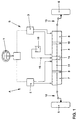
- the hydraulic actuator 4 is designed as a double cylinder unit, both of which Cylinder rooms 7, 8 each hold a piston 9, 10.
- the pistons 9, 10 are on one common, continuous piston rod 11 arranged in a manner known per se acts on actuators 12, 13 on the steerable vehicle wheels 5, 6.
- the Separation chamber 14 is in the area by means of sealing elements not shown here the piston rod 11 carried out opposite the adjacent cylinder spaces 7, 8 sealed and is located on one of the cylinder rooms 7, 8 independent Pressure level.
- the separation chamber 14 can be at ambient pressure, for example.
- the hydraulic steering system is related to its safety-related facilities constructed redundantly, so that if one of the two hydraulic circuits A or B fails a safe steering function is guaranteed.
- the separation chamber 14 causes in the event of a leak between the separation chamber 14 and one of the two adjacent ones Cylinder rooms 7 or 8 do not function in any way in the other cylinder room is impaired and thus the function of the steering system is not impaired.
- the actuator 4 is shown in detail.
- the separation chamber 14 is by means of two Shaft seals 17, 18 sealed against the cylinder spaces 7, 8.
- the drain pipe 15 of FIG. 1 is not shown here, but it can be connected to the separation chamber 14 leading line channel 19 are connected.
- the two cylinder rooms 7, 8 can via hydraulic connections 20 to 23 to the hydraulic devices 2, 3 (FIG. 1) of the two Hydraulic circuits A, B are connected.
- Leak warning device can be found on the separation chamber 14 or can be connected to the drain line 15 (FIG. 1).
- An occurring Leakage can also be determined by means of pressure sensors Pressure deviation between the two cylinder spaces 7, 8 can be determined and at one an unacceptable pressure deviation, an error signal or a leak warning indicator trigger.
Landscapes
- Engineering & Computer Science (AREA)
- Mechanical Engineering (AREA)
- Chemical & Material Sciences (AREA)
- Combustion & Propulsion (AREA)
- Transportation (AREA)
- Physics & Mathematics (AREA)
- Fluid Mechanics (AREA)
- General Engineering & Computer Science (AREA)
- Power Steering Mechanism (AREA)
Applications Claiming Priority (2)
| Application Number | Priority Date | Filing Date | Title |
|---|---|---|---|
| DE1999118354 DE19918354A1 (de) | 1999-04-22 | 1999-04-22 | Hydraulisches Stellteil zur Betätigung der Lenkung von Kraftfahrzeugen |
| DE19918354 | 1999-04-22 |
Publications (2)
| Publication Number | Publication Date |
|---|---|
| EP1046570A2 true EP1046570A2 (fr) | 2000-10-25 |
| EP1046570A3 EP1046570A3 (fr) | 2002-12-11 |
Family
ID=7905545
Family Applications (1)
| Application Number | Title | Priority Date | Filing Date |
|---|---|---|---|
| EP00105906A Ceased EP1046570A3 (fr) | 1999-04-22 | 2000-03-22 | Dispositif de commande hydraulique pour commander la direction de véhicules automobiles |
Country Status (2)
| Country | Link |
|---|---|
| EP (1) | EP1046570A3 (fr) |
| DE (1) | DE19918354A1 (fr) |
Cited By (5)
| Publication number | Priority date | Publication date | Assignee | Title |
|---|---|---|---|---|
| WO2003053765A1 (fr) * | 2001-12-11 | 2003-07-03 | Thyssenkrupp Presta Steertec Gmbh | Dispositif d'orientation par cables a deux circuits a coulisseaux communs |
| EP1431163A3 (fr) * | 2002-12-17 | 2004-12-15 | Still Gmbh | Dispositif à actionnement hydraulique |
| WO2009156062A1 (fr) * | 2008-06-23 | 2009-12-30 | Mt Aerospace Ag | Réservoir destiné à recevoir, stocker et fournir des liquides et des matières visqueuses, en particulier de l'eau potable ou du carburant, et utilisation de celui-ci |
| GB2464728A (en) * | 2008-10-27 | 2010-04-28 | Agco Gmbh | Hydraulic steering device with redundancy |
| NL1037276C2 (nl) * | 2009-09-11 | 2011-03-14 | Advanced Public Transp Systems B V | Stuurinrichting voor een via tenminste een eerste as automatisch gestuurd en tijdens bedrijf langs een vooraf gedefinieerd traject verplaatsbaar voertuig, alsmede een voertuig voorzien van een dergelijke stuurinrichting. |
Families Citing this family (1)
| Publication number | Priority date | Publication date | Assignee | Title |
|---|---|---|---|---|
| SE543750C2 (en) | 2019-11-22 | 2021-07-13 | Scania Cv Ab | A method for detecting leakage in a hydraulic steering system, a control device, a vehicle, a computer program and a computer-readable medium |
Family Cites Families (4)
| Publication number | Priority date | Publication date | Assignee | Title |
|---|---|---|---|---|
| US4410193A (en) * | 1979-11-14 | 1983-10-18 | Howard D U | Remotely adjustable compensator for centering steering systems |
| DE4133188A1 (de) * | 1990-10-08 | 1992-04-09 | Zahnradfabrik Friedrichshafen | Dichtungsanordnung |
| DE19627893C1 (de) * | 1996-07-11 | 1997-11-13 | Daimler Benz Ag | Hydraulisch betätigte Lenkung für Kraftfahrzeuge |
| DE19918225A1 (de) * | 1999-04-22 | 2000-11-02 | Daimler Chrysler Ag | Randwinkelsteller |
-
1999
- 1999-04-22 DE DE1999118354 patent/DE19918354A1/de not_active Withdrawn
-
2000
- 2000-03-22 EP EP00105906A patent/EP1046570A3/fr not_active Ceased
Cited By (8)
| Publication number | Priority date | Publication date | Assignee | Title |
|---|---|---|---|---|
| WO2003053765A1 (fr) * | 2001-12-11 | 2003-07-03 | Thyssenkrupp Presta Steertec Gmbh | Dispositif d'orientation par cables a deux circuits a coulisseaux communs |
| US7331419B2 (en) | 2001-12-11 | 2008-02-19 | Thyssenkrupp Presta Steertec Gmbh | Dual-circuit steer-by-wire steering system comprising a common cradle |
| EP1431163A3 (fr) * | 2002-12-17 | 2004-12-15 | Still Gmbh | Dispositif à actionnement hydraulique |
| US6968685B2 (en) | 2002-12-17 | 2005-11-29 | Still Gmbh | Hydraulic drive |
| WO2009156062A1 (fr) * | 2008-06-23 | 2009-12-30 | Mt Aerospace Ag | Réservoir destiné à recevoir, stocker et fournir des liquides et des matières visqueuses, en particulier de l'eau potable ou du carburant, et utilisation de celui-ci |
| GB2464728A (en) * | 2008-10-27 | 2010-04-28 | Agco Gmbh | Hydraulic steering device with redundancy |
| NL1037276C2 (nl) * | 2009-09-11 | 2011-03-14 | Advanced Public Transp Systems B V | Stuurinrichting voor een via tenminste een eerste as automatisch gestuurd en tijdens bedrijf langs een vooraf gedefinieerd traject verplaatsbaar voertuig, alsmede een voertuig voorzien van een dergelijke stuurinrichting. |
| WO2011031150A1 (fr) * | 2009-09-11 | 2011-03-17 | Advanced Public Transport Systems B.V. | Dispositif de direction pour un véhicule pouvant être déplacé, en fonctionnement, sur une trajectoire prédéfinie et dirigé automatiquement par au moins un premier essieu, et véhicule pourvu de ce dispositif |
Also Published As
| Publication number | Publication date |
|---|---|
| EP1046570A3 (fr) | 2002-12-11 |
| DE19918354A1 (de) | 2000-10-26 |
Similar Documents
| Publication | Publication Date | Title |
|---|---|---|
| DE19627893C1 (de) | Hydraulisch betätigte Lenkung für Kraftfahrzeuge | |
| DE3330387C2 (fr) | ||
| EP3371018B1 (fr) | Soupape de limitation de pression | |
| EP2691674B1 (fr) | Dispositif pneumatique d'assistance de force de changement de rapport | |
| DE102016014485A1 (de) | Hauptbremszylinderanordnung mit Positionsgeberelement und Dichtungsanordnung | |
| DE2507997A1 (de) | Bremskraftregler fuer eine zweikreisbremsanlage | |
| DE102018214006A1 (de) | Hydrauliksystem sowie Kraftfahrzeuggetriebe | |
| EP1046570A2 (fr) | Dispositif de commande hydraulique pour commander la direction de véhicules automobiles | |
| DE2642993A1 (de) | Kombinierter hydraulik- und vakuum- servokraftgeber | |
| DE19962124A1 (de) | Hydraulisches Zweikreis-Lenksystem | |
| DE19855405B4 (de) | Hydraulische Servolenkung für Kraftfahrzeuge | |
| DE102008035335A1 (de) | Druckmittelbetätigte Bremsvorrichtung für Kraftfahrzeuge | |
| EP3429898B1 (fr) | Soupape de relâchement de frein de stationnement pour un véhicule tracté | |
| DE112007001692B4 (de) | Hydraulisches System | |
| DE2622975A1 (de) | Zugfahrzeugsicherheitsventil | |
| DE4204883C1 (en) | Gearbox selector fork actuating mechanism with ram - has hollow piston containing two auxiliary pistons working with stops in it and in ram cylinder | |
| DE19536219C1 (de) | Hydraulikleitung mit integriertem, drucklosem Rücklauf | |
| DE2154229C3 (de) | Hilfskraftunterstützte, hydraulische Bremsbetätigungsanlage, insbesondere für Kraftfahrzeuge | |
| DE19909920A1 (de) | Sicherheitsschaltung für einen pneumatischen Motor | |
| DE102004029883B4 (de) | Lenkhilfevorrichtung für ein Fahrzeug | |
| DE102017116609A1 (de) | Überströmventil mit integriertem Druckbegrenzungsventil für ein Luftaufbereitungssystem eines Fahrzeugs, insbesondere eines Nutzfahrzeugs | |
| DE102004041703B4 (de) | Hydraulische Lenkung eines Fahrzeugs | |
| DE29822443U1 (de) | Absturzsicherung für Hubtische, Hebebühnen u.dgl. | |
| DE2619900A1 (de) | Steuerventil | |
| DE102007051039B4 (de) | Wegeventil in Kolbenschieberbauweise mit zwei Steuerkolben |
Legal Events
| Date | Code | Title | Description |
|---|---|---|---|
| PUAI | Public reference made under article 153(3) epc to a published international application that has entered the european phase |
Free format text: ORIGINAL CODE: 0009012 |
|
| AK | Designated contracting states |
Kind code of ref document: A2 Designated state(s): AT BE CH CY DE DK ES FI FR GB GR IE IT LI LU MC NL PT SE |
|
| AX | Request for extension of the european patent |
Free format text: AL;LT;LV;MK;RO;SI |
|
| PUAL | Search report despatched |
Free format text: ORIGINAL CODE: 0009013 |
|
| AK | Designated contracting states |
Kind code of ref document: A3 Designated state(s): AT BE CH CY DE DK ES FI FR GB GR IE IT LI LU MC NL PT SE |
|
| AX | Request for extension of the european patent |
Free format text: AL;LT;LV;MK;RO;SI |
|
| RIC1 | Information provided on ipc code assigned before grant |
Free format text: 7B 62D 5/12 A, 7F 15B 11/036 B, 7B 62D 5/30 B |
|
| 17P | Request for examination filed |
Effective date: 20030611 |
|
| AKX | Designation fees paid |
Designated state(s): AT BE CH CY DE DK ES FI FR GB GR IE IT LI LU MC NL PT SE |
|
| 17Q | First examination report despatched |
Effective date: 20030905 |
|
| STAA | Information on the status of an ep patent application or granted ep patent |
Free format text: STATUS: THE APPLICATION HAS BEEN REFUSED |
|
| 18R | Application refused |
Effective date: 20040416 |