EP1046751A2 - Appareil de tamisage pour eaux usées - Google Patents
Appareil de tamisage pour eaux usées Download PDFInfo
- Publication number
- EP1046751A2 EP1046751A2 EP20000303402 EP00303402A EP1046751A2 EP 1046751 A2 EP1046751 A2 EP 1046751A2 EP 20000303402 EP20000303402 EP 20000303402 EP 00303402 A EP00303402 A EP 00303402A EP 1046751 A2 EP1046751 A2 EP 1046751A2
- Authority
- EP
- European Patent Office
- Prior art keywords
- washing tank
- screening apparatus
- sewage
- screen
- screenings
- Prior art date
- Legal status (The legal status is an assumption and is not a legal conclusion. Google has not performed a legal analysis and makes no representation as to the accuracy of the status listed.)
- Withdrawn
Links
- 238000012216 screening Methods 0.000 title claims abstract description 124
- 239000010865 sewage Substances 0.000 title claims abstract description 85
- 238000005406 washing Methods 0.000 claims abstract description 125
- 239000007788 liquid Substances 0.000 claims abstract description 32
- 230000000694 effects Effects 0.000 claims abstract description 8
- 230000007246 mechanism Effects 0.000 claims description 37
- 239000000463 material Substances 0.000 claims description 23
- 238000005056 compaction Methods 0.000 claims description 11
- 238000007790 scraping Methods 0.000 claims description 7
- 230000004044 response Effects 0.000 claims description 2
- 229920003023 plastic Polymers 0.000 description 5
- 239000004033 plastic Substances 0.000 description 5
- 239000011343 solid material Substances 0.000 description 5
- 230000009471 action Effects 0.000 description 4
- 239000007791 liquid phase Substances 0.000 description 4
- 238000004140 cleaning Methods 0.000 description 3
- 239000000356 contaminant Substances 0.000 description 3
- 238000011109 contamination Methods 0.000 description 3
- 239000007787 solid Substances 0.000 description 3
- 230000008901 benefit Effects 0.000 description 2
- 239000002184 metal Substances 0.000 description 2
- 238000002156 mixing Methods 0.000 description 2
- 229910000831 Steel Inorganic materials 0.000 description 1
- 230000004308 accommodation Effects 0.000 description 1
- 238000005273 aeration Methods 0.000 description 1
- 230000001680 brushing effect Effects 0.000 description 1
- 239000000919 ceramic Substances 0.000 description 1
- 239000011248 coating agent Substances 0.000 description 1
- 238000000576 coating method Methods 0.000 description 1
- 150000001875 compounds Chemical class 0.000 description 1
- 239000000383 hazardous chemical Substances 0.000 description 1
- 231100000206 health hazard Toxicity 0.000 description 1
- 238000000034 method Methods 0.000 description 1
- 239000002245 particle Substances 0.000 description 1
- 229920000573 polyethylene Polymers 0.000 description 1
- 230000008569 process Effects 0.000 description 1
- -1 rags Substances 0.000 description 1
- 230000000717 retained effect Effects 0.000 description 1
- 239000010959 steel Substances 0.000 description 1
Images


Classifications
-
- E—FIXED CONSTRUCTIONS
- E02—HYDRAULIC ENGINEERING; FOUNDATIONS; SOIL SHIFTING
- E02B—HYDRAULIC ENGINEERING
- E02B8/00—Details of barrages or weirs ; Energy dissipating devices carried by lock or dry-dock gates
- E02B8/02—Sediment base gates; Sand sluices; Structures for retaining arresting waterborne material
- E02B8/023—Arresting devices for waterborne materials
- E02B8/026—Cleaning devices
Definitions
- the invention relates to a sewage screening apparatus for removing solid materials from a sewage flow.
- the effluent flow entering a sewage treatment plant contains solid materials, such as rags, paper, polythene and other plastic sheeting, and the like, which cannot be processed by the treatment plant.
- Solids can be removed from the flow by screens or sieves which capture the solids.
- the screens or sieve are then periodically or continuously operated for cleaning to remove the captured solids, commonly referred to as screenings, for de-watering and compaction and subsequent disposal.
- screening apparatus known in the art is the "continuous-belt screen" which includes a continuous belt screen, driven by means of a drive mechanism, which presents a continuous, moving screening area to the input sewage flow to effect removal of screenings within the sewage flow.
- screenings removed from the flow are as free as possible from any faecal material.
- screenings removed from the sewage flow by the continuous-belt screen are passed to a secondary washing stage, remote from the screening apparatus, to wash the screenings prior to compaction and removal from the site.
- additional conveying means are required for conveying the screenings to the secondary washing stage and subsequently onwards to the de-watering and compaction stage.
- the use of a secondary washing stage is disadvantageous in terms of complexity and cost.
- EP 0 592 508 describes an alternative apparatus for cleaning screenings to be removed from a sewage flow.
- removal of the screenings is effected by means of a screw conveyor having a perforated trough through which sewage in the liquid phase passes.
- An agitator in the form of an impeller device, is used to create turbulence in the sewage flow causing faecal contaminants to be washed from the screenings prior to their entry to the screw conveyor and their subsequent removal from the flow.
- the screenings cannot pass through the perforated trough and are compacted by the screw conveyor for subsequent disposal from the apparatus.
- a disadvantage of the apparatus is that it has a relatively low sewage flow capacity and, typically, the apparatus can only be used with sewage flow rates of less than 300-400 litres per second.
- the apparatus is not well suited for use as a primary sewage screening system.
- the apparatus cannot be employed in a sewage treatment plant serving areas where it is necessary to process a large sewage flow, such as areas of high population.
- the washing action is effected by repeatedly removing and reintroducing screenings into the region of turbulence by periodically reversing the direction of the screw conveyor during operation. Repeatedly reversing the direction of the screw conveyor in this way is mechanically inconvenient.
- a sewage screening apparatus comprising;
- the apparatus has a large flow capacity by virtue of the large screening area presented by the continuous belt screen.
- the apparatus therefore provides the advantage that it can be used for screening a high volume sewage flow and is therefore particularly suitable for use in a sewage treatment plant serving highly populated areas. Furthermore, owing to its increased capacity, the apparatus is suitable for use as a primary sewage screening apparatus.
- the screenings removed from the screen arrangement need not be passed through a second, remote washing stage prior to their removal from the sewage treatment plant.
- the washing apparatus includes a washing tank having impeller means located therein, the washing tank having a back plate and a front plate.
- the impeller means may be one or more rotary impeller. At least one rotary impeller may be mounted in the back plate of the washing tank. In addition, or alternatively, at least one rotary impeller may be mounted in the front plate of the washing tank.
- the back plate of the washing tank preferably forms part of a back plate of the screen arrangement.
- the apparatus also includes a drive mechanism for driving the belt screen, the drive mechanism being mounted externally of the screen arrangement. It is usual in conventional continuous belt screen arrangements for the drive mechanism to take the form of a driving wheel located within the head space of the screen arrangement. Mounting the driving mechanism externally of the screen arrangement enables the washing apparatus to be accommodated in the head space of the screen arrangement. Furthermore, contamination of the drive mechanism by the sewage flow is avoided.
- the drive mechanism comprises a driven chain carrying a plurality of bracket members for cooperation with a plurality of link members mounted on the belt screen, each of the link members having a drive pin member projecting therefrom, the bracket members cooperating with the projecting pin member to lift the link members and thereby drive the belt screen.
- each of the link members has two drive pin members, one projecting from each side of the link member, and each bracket member is bifurcated, the two fingers of the bracket member extending one on either side of the link member to engage with a corresponding drive pin member.
- the drive mechanism is not limited to use in the screening apparatus of the present invention and may be employed in any sewage screening apparatus having a driven screening belt.
- the screening apparatus further includes brushing means, such as a rotary brush, housed within the head space of the screen arrangement, to effect removal of screenings captured by the continuous belt screen into the washing apparatus.
- the washing tank also includes a weir over which an outlet flow from the washing tank, including the washed screenings, flows into conveyance means for conveying the outlet flow to a subsequent de-watering and compaction stage.
- the conveyance means may be a launder or a screw conveyor.
- the washing tank also includes covering means to prevent screenings removed from the continuous belt screen from passing directly into the conveyance means without passing through the washing tank.
- the washing tank also includes scraping means for scraping materials, including screenings, from the rotary brush into the washing tank.
- the scraping means may be provided by an upper edge of a side wall of the washing tank.
- the washing tank also includes a drainage point within its base to enable drainage of the washing tank.
- the base of the washing tank is of substantially curved or rounded form or the base is formed from separate plates having mitred corners. A base of this shape serves to enhance the mixing and turbulation of the tank contents.
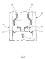
- a conventional screening apparatus for use in a sewage treatment plant includes a number of screen panels 12, each panel 12 being formed from a perforated metal sheet.
- the screen panels 12 are connected so as to form a continuous loop providing a belt screen 11, each screen panel 12 being connected to the adjacent screen panels, one on each side, by hinging means 14.
- the hinging means 14 may be in the form of a series of interdigitated lugs (not shown in detail), arranged along the edge of each panel 12, in which a retaining pin is received, the retaining pin passing through the lugs on adjacent panels 12 to secure adjacent panels together.
- the continuous belt screen 11 is driven by a drive mechanism (not shown in Figure 1) such that the screen panels 12 are conveyed upwardly on one side of the arrangement 10 and downwardly on the other side in a direction, as indicated by arrows 18.
- a drive mechanism not shown in Figure 1
- Such screen arrangements are well known in the art and may be referred to as “continuous belt screens", as the screen panels 12 form a continuous belt, driven by the drive mechanism, which presents a substantially continuous, moving screening area to the input sewage flow.
- the sewage flow 16 contains solid materials (not shown), such as rags, paper, plastics materials and stones, which cannot be processed by the treatment plant.
- the screen panels 12 are formed from sheets of perforated metal, the perforations of which 22 enable the liquid phase of the sewage to pass through the panels 12 onward to the subsequent processing stages of the treatment plant.
- the perforations 22 are such that solid materials in the sewage flow 16, having a greater dimension than the perforations, are captured.
- the liquid phase of the sewage is therefore passed out from the screen arrangement 10 through the continuous belt screen 11 on each side and through that part at the base, whilst the screenings are retained.
- FIG. 2 shows the screen arrangement 10 housed within the main sewage channel 24 of the processing plant. Seal points 26 between the belt screen and the main channel 24 separate the input sewage flow 16 from the screened output flow 28.
- Hooks or prongs 30 are arranged internally on the belt screen 11 at spaced locations around the loop.
- the hooks 30 are usually located between adjoining screen panels 12 and serve to capture the screenings contained within the sewage flow 16 as the belt screen passes continuously therethrough.
- the screenings may be removed from the belt screen 11 by means of a rotary brush 32 housed within the head space 20 of the screen arrangement 10 as they are conveyed through the head space 20 past the rotary brush 32.
- the apparatus also includes a hopper 34, housed within the head space 20, into which captured screenings, contaminated by faecal materials, are dislodged from the belt screen 11 by the rotary brush 32.
- aqueous liquid 36 is passed through a sparge washing system 40 onto the belt screen 11 to flush any materials which become entrapped in the perforations 22 of the screen panels 12.
- the screenings removed by the rotary brush 32, along with any materials flushed from the belt screen 11 by the liquid 36, are then discharged from the hopper 34 into a launder 42 which carries the screenings to a subsequent washing stage.
- the subsequent washing stage is remote from the screen arrangement 10 and therefore additional conveying means are required for conveying the screenings to the secondary washing stage and subsequently onwards to the de-watering and compaction stage. The complexity and cost of the apparatus is therefore increased.
- the continuous belt screen It is common for the continuous belt screen to be driven by means of a rotating wheel mechanism located within the head space 20 at the top of the screen arrangement 10. However, if the head space 20 accommodates this rotating wheel mechanism, the rotary brush 32 cannot then easily be accommodated therein.
- the present invention overcomes this problem, as will be described hereinafter.
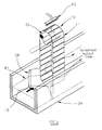
- the screening apparatus of the present invention includes a screen arrangement 10, as shown in Figure 1, and a washing apparatus, referred to generally as 43.
- the washing apparatus 43 is housed within the head space 20 of the screen arrangement 10, the head space 20 being that region within the belt screen 11 above the level of liquid sewage.
- the washing apparatus may be housed anywhere above the sewage level within the screen arrangement 10 but is preferably housed towards the upper portion of the head space 20.
- the washing apparatus is generally of the kind described in EP 0 557 030, and includes a washing tank 46 and an impeller device 48, such as a rotary impeller, housed within the washing tank 46.
- a washing liquid 50 is introduced into the washing tank 46 by means of a sparge washing system (not shown), filling the washing tank 46 to level 52.
- the washing liquid 50 also serves to flush any materials from the belt screen 11 which have become entrapped in the perforations 22 of the screen panels 12.
- the impeller 48 is driven by a motor (not shown in Figure 3) and serves to create a turbulence effect within the contents of the washing tank 46.
- the brush 32 removes the screenings from the belt screen 11 into the washing tank 46.
- the hooks 30 are grouped together to form rows of hooks spaced internally around the loop. The hooks may be located between adjoining screen panels 12, although they need not be included between each of the adjoining panels 12.
- the screenings introduced into the washing tank 46 are therefore subjected to a rigorous swirling motion, as indicated by arrows 54, produced by the driven rotary impeller 48.
- the swirling motion serves to wash the screenings and thereby removes any faecal contaminants which are entrapped with the screenings.
- the washing tank 46 includes a baffle plate 60 arranged underneath the launder 58.
- the baffle plate 60 serves to separate the washing tank 46 into two parts; a primary washing part, in which the region of turbulence washes the screenings introduced thereto (as indicated by arrows 54) and a secondary outlet part from which washed screenings are discharged to the launder 58 in the outlet flow.
- the washing tank 46 also includes a cover 62, arranged above the launder 58, to prevent screenings brushed from the belt screen 11 by-passing the washing process within the tank 46 and falling directly into the launder 58.
- the side wall 64 of the washing tank 46 extends upwardly towards the rotary brush 32, thereby providing a scraping edge to aid removal of screenings from the brush 32 into the washing tank 46.
- FIG 4 shows a side view of the washing tank 46 housed within the screen arrangement 10.
- the impeller 48 is driven by a motor 70 mounted in a back plate 72 of the washing tank 46 such that the motor is external to the washing tank 46.
- the back plate 72 also forms part of the back plate of the screen arrangement 10.
- the motor 70 is also mounted externally to the screen arrangement 10, thereby avoiding contamination of the motor 70 by the effluent flow within the screen arrangement 10. Removal of the back plate 72 enables easy access to the internal parts of the washing tank 46, for example for cleaning purposes.
- the direction of rotation of the impeller 48 is towards the incoming screenings (i.e. anti-clockwise as viewed in Figure 3).
- the swirling motion imparted to the contents of the washing tank 46 acts on the screenings so as to force them into the primary washing part of the washing tank 46.
- the screenings are maintained within the region of turbulence for as long as possible, thereby optimising the washing effect.
- the base 78 of the washing tank 46 is of substantially curved or rounded form or is formed from separate plates having mitred corners.
- a base having this shape serves to enhance the mixing and turbulation of the tank contents.
- a drainage point 80 may be provided in the base region 78 of the washing tank 46. The drainage point 80 also enables the contents of the tank 46 to be emptied, for example if access to the impeller is required if any damage has occurred thereto. As described previously, access to the impeller 48 can be achieved by removing the back plate 72.
- the swirling motion generated by the impeller assists in breaking the faecal materials into finely comminuted form.
- the inner surface of the washing tank 46 may be provided with an abrasive lining so that, as the faecal materials are thrown against the wall of the tank by the turbulent flow within the washing tank, mechanical attrition of the faecal materials occurs.
- the abrasive lining on the inner wall of the washing tank 46 may be a metallic or ceramic particle based abrasive coating.
- the comminution of the faecal materials in this way is advantageous as any liquefied faecal materials passing over the weir with the screenings will be separated from screenings in the subsequent de-watering and compaction stage and can then be re-supplied to the sewage flow channel for further processing in the sewage treatment plant. Maintaining the faecal materials within the sewage flow ensures the biological loading of the sewage treatment plant is maintained.
- the outlet flow from the weir 56 therefore includes washed screenings, liquefied faecal material and washing liquid.
- the outlet flow discharged over the weir 56 into the launder 58 is conveyed to the subsequent de-watering and compaction stage of the apparatus.
- the de-watering and compaction stage may include a screw compactor of the kind described in EP 0 557 030.
- Such a screw compactor includes a perforated trough region and a rotatable screw.
- the washing liquid and the liquefied faecal materials in the outlet flow can pass through the perforated trough, whilst the washed screenings are compacted by the rotating screw.
- the compacted screenings can then be safely disposed of in an incinerator or into a removal vehicle and the washing liquid and the liquefied faecal materials, being free from screenings, are returned to the sewage flow for further treatment.
- launder used for conveying screenings from the weir 56 to the subsequent de-watering and compaction stage may be replaced with another suitable conveyance means, such as a screw conveyor.
- the screen arrangement 10 is housed in the main sewage channel 24, as shown in Figure 5.
- the washing apparatus shown in Figure 3 is not shown in Figure 5 but, as described hereinbefore, is located above the sewage level, illustrated generally by the dotted line 81.
- the continuous belt screen 11 presents a large screening area to the input sewage flow 16, the screening area being provided by the belt screen 11 on two vertical sides of the screen arrangement 10 and at the base of the screen arrangement.
- the screening apparatus therefore has a large sewage flow capacity and, typically, is capable of screening an input sewage flow at a rate of up to 3000 litres per second.
- the apparatus is therefore particularly suitable for use in areas having a high population.
- the apparatus is suitable for use as a primary sewage screening apparatus.
- the dimensions of the washing tank 46 housed within the screen arrangement 10 will be determined by the volume of sewage to be passed through the sewage screening apparatus.
- Each of the impellers may be mounted on the back plate 72 or, alternatively, one or more impeller may be mounted on a front plate of the washing tank 46 oppositely facing the back plate 72.
- the washing liquid introduced into the washing tank 46 is an aqueous liquid and may include a washing compound to aid the washing process.
- the impeller device 48 is driven by the motor 70 during the period of operation of the continuous belt screen 11. However, it is preferable if the impeller is driven for a longer period than the belt screen so that the washing action continues after operation of the belt screen has ceased. Thus, all the screenings removed from the belt screen are washed fully. It may also be preferable to pause operation of the impeller during operation of the belt screen 11 as re-starting of impeller rotation can cause any materials which have become attached to the impeller to be dislodged therefrom. In addition, aeration within the tank contents which results from the impeller action causes the screenings to float to the top of the tank 46 (i.e. towards the weir 56) when impeller motion stops.
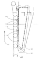
- the drive mechanism for the belt screen is mounted externally to the screen arrangement 10 on a sidewall of the screen arrangement 10, the drive mechanism engaging with both sides of the belt screen 11 as it passes through the head space 20 to effect the driving connection.
- the drive mechanism for this side includes a roller chain 90, formed from a plurality of chain links 92, and driven by means of a chain wheel 94 mounted on a drive shaft 96.
- the drive shaft 96 is driven by means of a motor 97 in the direction of arrow 102, the roller chain 90 therefore being driven by the chain wheel 94 in the direction of arrows 104.
- Idler wheels 98,100 hold the roller chain 90 under tension, the roller chain tension being adjustable by means of an adjustable tensioning plate 106.
- the face of the adjustable tensioning plate 108 is formed from a high density plastic material.
- link member 110 Mounted at each end of the screen panels 12 forming the belt screen 11 is a link member 110. As described previously, the screen panels 12 are connected together by means of hinge pins 14, passing through a plurality of interdigitated lugs (not shown) arranged along the edge of each screen panel 12. The hinge pins 14 also pass through apertures formed in the link members 110, thereby securing the link members 110 to their respective screen panel 12. Each of the link members 110 also includes a drive pin 114, or peg, projecting laterally therefrom.
- the roller chain 90 carries bifurcated brackets 112, referred to as "lifting" brackets, by means of a connection with the chain links 92, the brackets being spaced on the roller chain 90 at locations corresponding to the positioning of the link members 110 of the belt screen 11.
- lifting bracket 112 is carried by the driven roller chain 90 around the base 91 of the roller chain 90 and subsequently upwards, the upper surface of the each of the fingers of the bracket 112 comes into contact with a corresponding drive pin 114 on a link member 110.
- the bracket 112 thereby serves to "lift” the drive pins 114, and hence the link member 110, in an upward direction, thus driving the belt screen 11.
- the tensioning plate 106 serves to ensure that the brackets 112 embrace the link members 110 at the correct depth so that the bracket provides the required lifting force for the drive pins 114.
- the link members 110 may be formed from a high density plastic material and are shaped to cooperate with vertically extending guide tracks 116 for guiding the link members 110 as they are driven in an upward direction by the driven roller chain 90.
- the guide tracks 116 may be formed from a high density plastic material and are supported by a steel angle track 118 which may form part of the outer housing of the screen arrangement 10. Equivalent guide tracks for the link members mounted on the other side of the belt screen 11 are also provided (not shown in Figure 6).
- the drive mechanism also provides an advantage over conventional drive mechanisms which are mounted on the top curve of the screen arrangement. By mounting the drive mechanism on a vertical side of the screen arrangement, the bearing load on the top curve is minimised and the wear on the apparatus is reduced. The operating life of the apparatus is therefore improved.
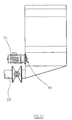
- valve arrangement 130 which is operable between open and closed positions to control the discharge of liquid and washed screenings from the washing tank 46.
- the valve arrangement 130 When the valve arrangement 130 is in the open position, liquid within the washing tank 46 and washed screenings are able to flow through an outlet port (not shown) provided in the washing tank 46, into the launder 58 to be discharged from the screening apparatus.
- the valve arrangement 130 When the valve arrangement 130 is in the closed position, the outlet port is closed such that liquid and the screenings are unable to flow from the washing tank 46 into the launder 58.
- the valve arrangement 130 is operable in response to an output signal from a sensor 132, as shown in Figure 10, for sensing the level of liquid within the washing tank 46.
- a sensor 132 as shown in Figure 10
- the output signal generated by the liquid level sensor 132 is used to initiate opening of the valve arrangement 130.
- the valve arrangement 130 remains open for a period of time which is sufficient to permit the washing tank 46 to drain to a liquid level no less than a lower level 136.
- the output signal generated by the sensor 132 is used to initiate closure of the valve arrangement 130. Under such circumstances, liquid within the washing tank 46 and washed screenings are unable to flow through the outlet port into the launder 58.
- the output signal from the sensor 132 is also used to control operation of the motor 70 for the impeller 48 such that, when the level of liquid within the washing tank 46 reaches the lower level 136, operation of the motor 70 is ceased. Operation of the impeller 38 therefore ceases when the level of liquid within the washing tank 46 reaches the lower liquid level 136.
- the output signals generated by the sensor 132 may be supplied to an electronic control unit (not shown), or a computer processor, for controlling operation of the valve arrangement 130 and the drive mechanism for the screen arrangement.
- an electronic control unit not shown
- a computer processor for controlling operation of the valve arrangement 130 and the drive mechanism for the screen arrangement.
- the inset in Figure 6 shows the direction of travel of the belt screen 11 (as indicated by the arrows 18) when the drive mechanism is mounted on the right hand, vertical side of the screen arrangement and is driven in the direction of arrow 104.
- the direction of travel 18 may be reversed by mounting the drive mechanism on the left hand vertical side of the screen arrangement.
- the drive mechanism described hereinbefore is not limited to use in the sewage screening apparatus of the present invention and may be employed in any sewage screening apparatus having a driven screening belt.
Landscapes
- Engineering & Computer Science (AREA)
- General Engineering & Computer Science (AREA)
- Mechanical Engineering (AREA)
- Civil Engineering (AREA)
- Structural Engineering (AREA)
- Separation Of Solids By Using Liquids Or Pneumatic Power (AREA)
- Sewage (AREA)
- Treatment Of Sludge (AREA)
Applications Claiming Priority (2)
| Application Number | Priority Date | Filing Date | Title |
|---|---|---|---|
| GB9909266 | 1999-04-23 | ||
| GBGB9909266.0A GB9909266D0 (en) | 1999-04-23 | 1999-04-23 | Sewage screening apparatus |
Publications (2)
| Publication Number | Publication Date |
|---|---|
| EP1046751A2 true EP1046751A2 (fr) | 2000-10-25 |
| EP1046751A3 EP1046751A3 (fr) | 2002-12-18 |
Family
ID=10852059
Family Applications (1)
| Application Number | Title | Priority Date | Filing Date |
|---|---|---|---|
| EP00303402A Withdrawn EP1046751A3 (fr) | 1999-04-23 | 2000-04-20 | Appareil de tamisage pour eaux usées |
Country Status (4)
| Country | Link |
|---|---|
| EP (1) | EP1046751A3 (fr) |
| AU (1) | AU3009300A (fr) |
| CA (1) | CA2306405A1 (fr) |
| GB (1) | GB9909266D0 (fr) |
Cited By (3)
| Publication number | Priority date | Publication date | Assignee | Title |
|---|---|---|---|---|
| US8136673B2 (en) | 2007-11-14 | 2012-03-20 | The Haigh Engineering Company Ltd. | Grit elevator |
| CN112774277A (zh) * | 2021-01-13 | 2021-05-11 | 安徽金川建设工程有限公司 | 一种河道黑臭水体治理修复系统 |
| CN116329067A (zh) * | 2023-03-30 | 2023-06-27 | 徐州旺农生物科技有限公司 | 一种饲料生产除杂装置 |
Citations (1)
| Publication number | Priority date | Publication date | Assignee | Title |
|---|---|---|---|---|
| EP0592508A1 (fr) | 1991-07-05 | 1994-04-20 | Bischof Rudolf Gmbh | Procede et dispositif pour l'amelioration du traitement de matieres solides contenues dans les eaux usees, de sable, de dechets ou similaires. |
Family Cites Families (4)
| Publication number | Priority date | Publication date | Assignee | Title |
|---|---|---|---|---|
| GB2104402A (en) * | 1981-08-11 | 1983-03-09 | Jones & Attwood Ltd | Apparatus for removing solid material from sewage |
| US4812231A (en) * | 1988-08-17 | 1989-03-14 | Wieseman Enterprises, Inc. | Self cleaning rotating fine polishing filter screen apparatus |
| CA2089400C (fr) * | 1992-02-15 | 2002-08-13 | John Cedric Bache | Machine pour le lavage de fragments solides |
| GB9503340D0 (en) * | 1995-02-21 | 1995-04-12 | Jones & Attwood Ltd | Screen |
-
1999
- 1999-04-23 GB GBGB9909266.0A patent/GB9909266D0/en not_active Ceased
-
2000
- 2000-04-20 CA CA 2306405 patent/CA2306405A1/fr not_active Withdrawn
- 2000-04-20 EP EP00303402A patent/EP1046751A3/fr not_active Withdrawn
- 2000-04-20 AU AU30093/00A patent/AU3009300A/en not_active Withdrawn
Patent Citations (1)
| Publication number | Priority date | Publication date | Assignee | Title |
|---|---|---|---|---|
| EP0592508A1 (fr) | 1991-07-05 | 1994-04-20 | Bischof Rudolf Gmbh | Procede et dispositif pour l'amelioration du traitement de matieres solides contenues dans les eaux usees, de sable, de dechets ou similaires. |
Cited By (4)
| Publication number | Priority date | Publication date | Assignee | Title |
|---|---|---|---|---|
| US8136673B2 (en) | 2007-11-14 | 2012-03-20 | The Haigh Engineering Company Ltd. | Grit elevator |
| CN112774277A (zh) * | 2021-01-13 | 2021-05-11 | 安徽金川建设工程有限公司 | 一种河道黑臭水体治理修复系统 |
| CN116329067A (zh) * | 2023-03-30 | 2023-06-27 | 徐州旺农生物科技有限公司 | 一种饲料生产除杂装置 |
| CN116329067B (zh) * | 2023-03-30 | 2023-11-21 | 徐州旺农生物科技有限公司 | 一种饲料生产除杂装置 |
Also Published As
| Publication number | Publication date |
|---|---|
| GB9909266D0 (en) | 1999-06-16 |
| CA2306405A1 (fr) | 2000-10-23 |
| AU3009300A (en) | 2000-10-26 |
| EP1046751A3 (fr) | 2002-12-18 |
Similar Documents
| Publication | Publication Date | Title |
|---|---|---|
| CN210230110U (zh) | 工程建筑废料处理装置 | |
| KR101893203B1 (ko) | 스프링캡 내장형 레이크를 구비한 협잡물 제거용 스크린 | |
| EP1039055B1 (fr) | Dispositif de tamisage pour eaux usées | |
| US5378375A (en) | Apparatus and method of washing screenings | |
| US5098564A (en) | Automatic self-cleaning strainer assembly | |
| EP1046751A2 (fr) | Appareil de tamisage pour eaux usées | |
| US5993651A (en) | Water influent particle removing apparatus | |
| US5641360A (en) | Process and device for improving the treatment of sewage solids | |
| KR20210144030A (ko) | 협잡물과 침사물 동시 제거기능을 갖는 수직 스크린장치 | |
| JP4074927B2 (ja) | 洗浄処理装置 | |
| JP2003094069A (ja) | 汚水処理方法及び汚水処理装置 | |
| JPH07223719A (ja) | 脱水ケーキの破砕搬送機 | |
| JP4502531B2 (ja) | 沈砂及びし渣の処理装置 | |
| JP2004141818A (ja) | 沈砂池からの固形物の流体移送装置 | |
| US6365045B1 (en) | Apparatus for use in a sewage treatment plant | |
| JP3066642B1 (ja) | 建築廃材用破砕装置 | |
| JPH07213951A (ja) | 生ごみ処理装置 | |
| US6186336B1 (en) | Dredge with auxiliary grizzly | |
| KR200341020Y1 (ko) | 로타리 제진기 | |
| KR20230079590A (ko) | 협잡물의 이송이 용이한 스크린 장치 및 스크린 장치의 이상동작 대응 방법 | |
| JP2002363950A (ja) | 取水口塵芥除去装置 | |
| JPH07185388A (ja) | 沈砂洗浄機 | |
| CN214693659U (zh) | 一种生活废水净化处理设备 | |
| JP4349675B2 (ja) | 沈砂・し渣洗浄装置 | |
| KR200342805Y1 (ko) | 하수여과용 협작물 처리기 |
Legal Events
| Date | Code | Title | Description |
|---|---|---|---|
| PUAI | Public reference made under article 153(3) epc to a published international application that has entered the european phase |
Free format text: ORIGINAL CODE: 0009012 |
|
| AK | Designated contracting states |
Kind code of ref document: A2 Designated state(s): AT BE CH CY DE DK ES FI FR GB GR IE IT LI LU MC NL PT SE |
|
| AX | Request for extension of the european patent |
Free format text: AL;LT;LV;MK;RO;SI |
|
| PUAL | Search report despatched |
Free format text: ORIGINAL CODE: 0009013 |
|
| AK | Designated contracting states |
Kind code of ref document: A3 Designated state(s): AT BE CH CY DE DK ES FI FR GB GR IE IT LI LU MC NL PT SE |
|
| AX | Request for extension of the european patent |
Free format text: AL;LT;LV;MK;RO;SI |
|
| STAA | Information on the status of an ep patent application or granted ep patent |
Free format text: STATUS: THE APPLICATION IS DEEMED TO BE WITHDRAWN |
|
| 18D | Application deemed to be withdrawn |
Effective date: 20021101 |