EP1046762A2 - Elément de support pour la fixation frontale des extrémités longitudinales d'un lanterneau de toit voûté - Google Patents
Elément de support pour la fixation frontale des extrémités longitudinales d'un lanterneau de toit voûté Download PDFInfo
- Publication number
- EP1046762A2 EP1046762A2 EP00106653A EP00106653A EP1046762A2 EP 1046762 A2 EP1046762 A2 EP 1046762A2 EP 00106653 A EP00106653 A EP 00106653A EP 00106653 A EP00106653 A EP 00106653A EP 1046762 A2 EP1046762 A2 EP 1046762A2
- Authority
- EP
- European Patent Office
- Prior art keywords
- profile
- bearing element
- frame
- rungs
- plate
- Prior art date
- Legal status (The legal status is an assumption and is not a legal conclusion. Google has not performed a legal analysis and makes no representation as to the accuracy of the status listed.)
- Withdrawn
Links
Images



Classifications
-
- E—FIXED CONSTRUCTIONS
- E04—BUILDING
- E04D—ROOF COVERINGS; SKY-LIGHTS; GUTTERS; ROOF-WORKING TOOLS
- E04D13/00—Special arrangements or devices in connection with roof coverings; Protection against birds; Roof drainage ; Sky-lights
- E04D13/03—Sky-lights; Domes; Ventilating sky-lights
- E04D13/032—Supports or connecting means for sky-lights of vaulted shape
-
- E—FIXED CONSTRUCTIONS
- E04—BUILDING
- E04D—ROOF COVERINGS; SKY-LIGHTS; GUTTERS; ROOF-WORKING TOOLS
- E04D3/00—Roof covering by making use of flat or curved slabs or stiff sheets
- E04D3/02—Roof covering by making use of flat or curved slabs or stiff sheets of plane slabs, slates, or sheets, or in which the cross-section is unimportant
- E04D3/06—Roof covering by making use of flat or curved slabs or stiff sheets of plane slabs, slates, or sheets, or in which the cross-section is unimportant of glass or other translucent material; Fixing means therefor
- E04D3/08—Roof covering by making use of flat or curved slabs or stiff sheets of plane slabs, slates, or sheets, or in which the cross-section is unimportant of glass or other translucent material; Fixing means therefor with metal glazing bars
- E04D2003/0868—Mutual connections and details of glazing bars
- E04D2003/0881—Mutual connections and details of glazing bars on the eaves of the roof
Definitions
- the invention relates to a bearing element for an end Attachment of the longitudinal ends of a barrel-shaped Light band of a roof structure according to the generic term of Claim 1.
- a bearing element of this type is, for example, from DE 35 33 144 A1 known.
- the invention deals with the problem of one if possible large area of such a bearing element for attachment use differently structured light strips can. Different light strips can be worn in particular regarding the height of their rungs and the height of the plate elements.
- the invention is based on the general idea that opposite the base profile swiveling angle profile of the bearing element to be designed so that different in this high rungs only in one facing the base profile Partial area rest on the second leg. In this area openings are provided in this second leg, through the screws to attach a rung to it Legs are feasible.
- the frame profile to accommodate the Plate elements is each an independent, to the plate thickness adapted part that with the second leg of the Profile angle is screwed.
- a gable bearing element for receiving a gable-side plate of a light band, attached at right angles to the bearing element according to claim 1 can be, is the subject of claim 5.
- Die In this version, the gable wall can be flush with the respective longitudinal end face of a bearing element according to claim Complete 1.
- the light strip 1 is composed of curved in detail transparent plate elements 4 made of plastic, the rest on curved rungs 5 and firmly connected to them are.
- the light strip 1 is made of curved side by side Built up plate elements 4, these plate elements limit 4 lying on a common rung 5 against each other, wherein the abutting area by an overlying, cover rail connected to the rung and serving as a seal 6 is sealed.
- the rungs 5 are supported on the bearing elements 2, with to whom they are firmly connected.
- the bearing elements 2 exist from a screwed to the frame 3 of the roof structure Base profile 7 on which an angle profile 8 can be pivoted about an axis parallel to the longitudinal extent of the frame 3 is articulated.
- the rungs are supported at this angle 8 5 of the light band 1.
- the angle profile 8 consists of a first leg 9, which is articulated with the base profile 7 is connected and a second leg 10 which is rectangular protrudes from the first leg 9.
- the second leg 10 lies on one end face of the rungs 5 and is via screws 11 which through openings 12 in the grab the second leg 10 with the adjacent one Rung 5 firmly connected.
- the screws 11 engage within the rungs 5 into the screw channels 13 provided there.
- b clamping angle 16 is provided, which are anchored within the rungs 5 and the screwed to the cover rails 6 via clamping screws 17 are.
- the anchoring of the clamping angle 16 within the Rungs 5 is given by the fact that the clamping angle 16 in receiving rails 18 provided within the rungs 5 are positively inserted. Grab the clamping screws 17 through openings within the clamping angle 16 in inside of the cover rails 6 provided screw channels 20.
- the production of a light band in the execution according to the 3a, b can be made as follows.
- the bearing elements 2 are on the opposite frames 3, between which the light band 1 is to be formed, permanently installed.
- the assembly takes place in such a way that the Swivel axis between the base profiles 7 and the profile angle 8 of the bearing elements 2 in the edge area of the frames 3 still lies in the area of the respective frame. This ensures that from the light strip on the bearing elements 2 transferred forces not on a freely projecting area of the base profile 7 can attack.
- This is not a special one Stiffening of a cantilevered base profile area necessary because the basic profile is subject to its high stress Areas on the frame 3 below are sufficient can support safely.
- the rungs 5 correspond to the barrel shape of the light strip pre-bent and have, for example, a radius of curvature of 2,800 mm.
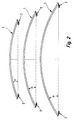
- equally curved rungs 5 can be used as shown in FIG. 2.
- the bearing elements 2 can be used by the articulated there Compensate profile angle 8.
- the rungs 5 are in the permanently mounted bearing elements 2 inserted and screwed. Then it becomes flexible Plate element 4 on one of the two opposite Bearing elements 2 firmly anchored and after bending around the Rungs 5 then with the opposite bearing element 2 tense. In the case of panel elements to be juxtaposed 4 is followed accordingly.
- the cover rail 6 is each bent and at their two ends over one each Clamping angle 16 fixed relative to the assigned rung 5 tense. Sealing elements are located in the cover rail 6, with which a seal between cover rails 6 and assigned Plate elements 4 is ensured.
- the cover rails 6 are only anchored at the end to the respective rung 5.
- the frame profiles 14, in which the ends of the plate elements 4 are bordered, are in the occupied by the clamping angles 16 Areas interrupted.
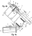
- the screw connection with the rung 5 ' is given by a screw 19, through an opening within the frame profile 14 'engages in a screw channel 20 of the rungs 5.
- the Screw channel 20 extends over the entire length of the Rungs 5 'and is U-shaped to the upper outside of the Rungs 5 designed open.
- the Decksehiene 6 is in the 4a, b, over their length several times through this cover rail penetrating screws 21 with the Rungs 5 'screwed, the screws 21 in the Engage screw channel 20 of rungs 5 '.
- the production of the light strip 1 according to FIGS. 4a, b is similar to that after the above-described execution and differs only in that already during bending the plate elements 4 and the cover rails 6 a screw the cover rails 6 on the rung 5 in the longitudinal direction the cover rails 6 progressively takes place.
- the rigidity of the rungs 5 according to FIGS. 3a, b can increased by inserting an additional inner profile 22 become.
- a flat, if possible transparent plastic plate 23 may be attached on a gable side of the light strip 1.
- a bearing element 2 'permanently mounted To attach this plastic plate 23 to an associated Frame 3 of the roof structure is on this frame 3 a bearing element 2 'permanently mounted.
- This bearing element 2 ' consists of a base profile firmly screwed to the frame 3 7 'and one suspended on its long side Gable frame profile 24.
- This bearing element shown in FIG. 1 2 ' enables a flush application in a simple manner the plastic plate 23 to the face of an adjacent one Bearing element 2.
- the connection of the gable frame profile 24 to the base profile 7 'of the bearing element 2' given by a kind of tongue and groove connection 25.
- the attachment the gable-side plastic plate 23 to the Rungs 5 and 5 ' are carried out in the usual way by a Gable angle 26 corresponding to FIG. 1.
- the advantage of the embodiment according to the invention is one modular structure of the light strip such that for different designed light strips as many of the same as possible Parts can be used.
Landscapes
- Engineering & Computer Science (AREA)
- Architecture (AREA)
- Civil Engineering (AREA)
- Structural Engineering (AREA)
- Roof Covering Using Slabs Or Stiff Sheets (AREA)
Applications Claiming Priority (2)
| Application Number | Priority Date | Filing Date | Title |
|---|---|---|---|
| DE1999118631 DE19918631A1 (de) | 1999-04-23 | 1999-04-23 | Lagerelement für eine stirnseitige Befestigung der Längsenden eines tonnenförmig gebogenen Lichtbandes einer Dachkonstruktion |
| DE19918631 | 1999-04-23 |
Publications (2)
| Publication Number | Publication Date |
|---|---|
| EP1046762A2 true EP1046762A2 (fr) | 2000-10-25 |
| EP1046762A3 EP1046762A3 (fr) | 2001-05-23 |
Family
ID=7905715
Family Applications (1)
| Application Number | Title | Priority Date | Filing Date |
|---|---|---|---|
| EP00106653A Withdrawn EP1046762A3 (fr) | 1999-04-23 | 2000-03-29 | Elément de support pour la fixation frontale des extrémités longitudinales d'un lanterneau de toit voûté |
Country Status (2)
| Country | Link |
|---|---|
| EP (1) | EP1046762A3 (fr) |
| DE (1) | DE19918631A1 (fr) |
Cited By (2)
| Publication number | Priority date | Publication date | Assignee | Title |
|---|---|---|---|---|
| DE10320415A1 (de) * | 2003-05-07 | 2004-12-02 | Heinrich Strunz Gmbh | Lichtbandsystem mit Thermofuss und Lastaufnahmebock |
| US7364007B2 (en) | 2004-01-08 | 2008-04-29 | Schlumberger Technology Corporation | Integrated acoustic transducer assembly |
Families Citing this family (2)
| Publication number | Priority date | Publication date | Assignee | Title |
|---|---|---|---|---|
| DE102022129042B3 (de) | 2022-11-03 | 2023-09-21 | additiveStream4D GmbH | Kalibriersystem und Kalibrierverfahren zur Kalibrierung eines Bauplattformsystems in einer additiven Fertigungsvorrichtung |
| WO2024094255A1 (fr) | 2022-11-03 | 2024-05-10 | additiveStream4D GmbH | Système de plateforme de construction pour fabrication additive |
Citations (1)
| Publication number | Priority date | Publication date | Assignee | Title |
|---|---|---|---|---|
| DE3533144A1 (de) | 1985-09-17 | 1987-04-02 | Eternit Ag | Auf einem aufsetzkranz oder dergleichen angeordnetes, gewoelbtes dachoberlicht |
Family Cites Families (5)
| Publication number | Priority date | Publication date | Assignee | Title |
|---|---|---|---|---|
| NL7801905A (en) * | 1978-02-21 | 1979-08-23 | Jacobus Kuin | Pivoting coupling securing building element to a support - has beads threading one into the other lengthways |
| US4539783A (en) * | 1983-09-12 | 1985-09-10 | O'keeffe's, Inc. | Barrell vault skylight system |
| NL8501419A (nl) * | 1985-05-17 | 1986-12-16 | Kuin Beheer B V | Samenstel ter inklemming, afdichting en bevestiging op een opstand van een meerwandig, lichtdoorlatend kunststofpaneel van een lichtstraat. |
| FR2709780B1 (fr) * | 1993-09-06 | 1997-07-11 | Guy Biguet | Gamme d'armatures pour parois translucides et leur dispositif de fabrication. |
| FR2727165B1 (fr) * | 1994-11-22 | 1996-12-27 | Audo Daniel | Ensemble de panneaux translucides a fixation mecanique exterieure non visible |
-
1999
- 1999-04-23 DE DE1999118631 patent/DE19918631A1/de not_active Withdrawn
-
2000
- 2000-03-29 EP EP00106653A patent/EP1046762A3/fr not_active Withdrawn
Patent Citations (1)
| Publication number | Priority date | Publication date | Assignee | Title |
|---|---|---|---|---|
| DE3533144A1 (de) | 1985-09-17 | 1987-04-02 | Eternit Ag | Auf einem aufsetzkranz oder dergleichen angeordnetes, gewoelbtes dachoberlicht |
Cited By (2)
| Publication number | Priority date | Publication date | Assignee | Title |
|---|---|---|---|---|
| DE10320415A1 (de) * | 2003-05-07 | 2004-12-02 | Heinrich Strunz Gmbh | Lichtbandsystem mit Thermofuss und Lastaufnahmebock |
| US7364007B2 (en) | 2004-01-08 | 2008-04-29 | Schlumberger Technology Corporation | Integrated acoustic transducer assembly |
Also Published As
| Publication number | Publication date |
|---|---|
| DE19918631A1 (de) | 2000-10-26 |
| EP1046762A3 (fr) | 2001-05-23 |
Similar Documents
| Publication | Publication Date | Title |
|---|---|---|
| DE3206871C1 (de) | Kombinations-Eindeckrahmen fuer nebeneinander einzubauende Dachfenster | |
| DE19536950C1 (de) | Rahmenschenkel für ein Rahmengestell eines Schaltschrankes | |
| EP0429431A2 (fr) | Couverture de façade par des éléments à double parois avec ventilation arrière | |
| DE2844015C2 (de) | Dichtungsprofil für Rolladenkästen | |
| DE19854452B4 (de) | Zusammenfügbare Profilschienen zur Abdeckung, Überbrückung und/oder Einfassung der Ränder von Boden- und/oder Wandbelägen | |
| EP1046762A2 (fr) | Elément de support pour la fixation frontale des extrémités longitudinales d'un lanterneau de toit voûté | |
| DE9003900U1 (de) | Holz-Metall-Rahmen für Fenster, Türen o.dgl. | |
| DE2929215A1 (de) | Rahmen fuer einen solarkollektor | |
| DE3943087C1 (fr) | ||
| DE3426027C2 (fr) | ||
| EP0023969B1 (fr) | Dispositif de fixation pour panneaux voûtés en matière synthétique de recouvrements | |
| DE2735975A1 (de) | Dachrinne | |
| DE3301940A1 (de) | Fenster oder tuer mit beplankungsleisten aus holz oder kunststoff | |
| DE3340476A1 (de) | Fahrzeugfenster mit einer verschiebbaren fensterscheibe | |
| DE9400115U1 (de) | Dichtungsprofil | |
| EP0477544B1 (fr) | Pièce de remplissage pour parcloses | |
| DE2914474C2 (fr) | ||
| DE19918632A1 (de) | Hohlprofil-Sprosse eines tonnenförmig gebogenen Lichtbandes einer Dachkonstruktion | |
| DE4321466A1 (de) | Zarge für ein Fenster | |
| DE8601903U1 (de) | Belichtungsvorrichtung | |
| EP0654567A2 (fr) | Système de vitrage d'une toiture | |
| DE7903745U1 (de) | Anschraubtasche zum anschlagen eines einbohrzapfenbandes | |
| DE2623781B2 (de) | Verkleidungsprofil für alte Blendrahmen | |
| DE10043544B4 (de) | Dichtungsstrang für einen Blendrahmen mit einem integrierten Flügelrahmen | |
| EP1653579B1 (fr) | Rail profilé pour construire un chassis, en particulier pour une armoire électrique |
Legal Events
| Date | Code | Title | Description |
|---|---|---|---|
| PUAI | Public reference made under article 153(3) epc to a published international application that has entered the european phase |
Free format text: ORIGINAL CODE: 0009012 |
|
| AK | Designated contracting states |
Kind code of ref document: A2 Designated state(s): AT CH DE LI |
|
| AX | Request for extension of the european patent |
Free format text: AL;LT;LV;MK;RO;SI |
|
| PUAL | Search report despatched |
Free format text: ORIGINAL CODE: 0009013 |
|
| AK | Designated contracting states |
Kind code of ref document: A3 Designated state(s): AT BE CH CY DE DK ES FI FR GB GR IE IT LI LU MC NL PT SE |
|
| AX | Request for extension of the european patent |
Free format text: AL;LT;LV;MK;RO;SI |
|
| RIC1 | Information provided on ipc code assigned before grant |
Free format text: 7E 04D 13/03 A, 7E 04D 3/08 B |
|
| 17P | Request for examination filed |
Effective date: 20010717 |
|
| AKX | Designation fees paid |
Free format text: AT CH DE LI |
|
| RAP1 | Party data changed (applicant data changed or rights of an application transferred) |
Owner name: J. EBERSPAECHER GMBH & CO. KG |
|
| 17Q | First examination report despatched |
Effective date: 20040126 |
|
| STAA | Information on the status of an ep patent application or granted ep patent |
Free format text: STATUS: THE APPLICATION IS DEEMED TO BE WITHDRAWN |
|
| 18D | Application deemed to be withdrawn |
Effective date: 20040608 |