EP1046839A2 - Elektronisches Steuergerät für ein Kraftfahrzeug-Automatikgetriebe und Verfahren zum Abgleichen eines Positionserkennungssensors - Google Patents
Elektronisches Steuergerät für ein Kraftfahrzeug-Automatikgetriebe und Verfahren zum Abgleichen eines Positionserkennungssensors Download PDFInfo
- Publication number
- EP1046839A2 EP1046839A2 EP00108563A EP00108563A EP1046839A2 EP 1046839 A2 EP1046839 A2 EP 1046839A2 EP 00108563 A EP00108563 A EP 00108563A EP 00108563 A EP00108563 A EP 00108563A EP 1046839 A2 EP1046839 A2 EP 1046839A2
- Authority
- EP
- European Patent Office
- Prior art keywords
- position detection
- detection sensor
- selector slide
- control device
- stored
- Prior art date
- Legal status (The legal status is an assumption and is not a legal conclusion. Google has not performed a legal analysis and makes no representation as to the accuracy of the status listed.)
- Granted
Links
- 230000005540 biological transmission Effects 0.000 title claims abstract description 21
- 238000000034 method Methods 0.000 title claims description 14
- 238000001514 detection method Methods 0.000 claims abstract description 47
- 230000001419 dependent effect Effects 0.000 claims abstract 2
- 238000006073 displacement reaction Methods 0.000 claims description 2
- 238000004519 manufacturing process Methods 0.000 description 7
- 238000011156 evaluation Methods 0.000 description 4
- 238000009434 installation Methods 0.000 description 4
- 230000005355 Hall effect Effects 0.000 description 2
- 230000003679 aging effect Effects 0.000 description 2
- 230000000295 complement effect Effects 0.000 description 2
- 238000012937 correction Methods 0.000 description 2
- 238000013461 design Methods 0.000 description 2
- 230000003068 static effect Effects 0.000 description 2
- 241001136792 Alle Species 0.000 description 1
- 238000012935 Averaging Methods 0.000 description 1
- 241000249931 Doronicum maximum Species 0.000 description 1
- 238000010521 absorption reaction Methods 0.000 description 1
- 239000000853 adhesive Substances 0.000 description 1
- 230000001070 adhesive effect Effects 0.000 description 1
- 229910052782 aluminium Inorganic materials 0.000 description 1
- XAGFODPZIPBFFR-UHFFFAOYSA-N aluminium Chemical compound [Al] XAGFODPZIPBFFR-UHFFFAOYSA-N 0.000 description 1
- 238000004364 calculation method Methods 0.000 description 1
- 239000000919 ceramic Substances 0.000 description 1
- 239000004020 conductor Substances 0.000 description 1
- 238000011161 development Methods 0.000 description 1
- 230000018109 developmental process Effects 0.000 description 1
- 230000007613 environmental effect Effects 0.000 description 1
- 239000011888 foil Substances 0.000 description 1
- 230000006870 function Effects 0.000 description 1
- 239000012208 gear oil Substances 0.000 description 1
- 230000001939 inductive effect Effects 0.000 description 1
- 239000007788 liquid Substances 0.000 description 1
- 230000007257 malfunction Effects 0.000 description 1
- 238000005259 measurement Methods 0.000 description 1
- 229910052751 metal Inorganic materials 0.000 description 1
- 239000002184 metal Substances 0.000 description 1
- 230000007935 neutral effect Effects 0.000 description 1
- 239000003921 oil Substances 0.000 description 1
- 239000000758 substrate Substances 0.000 description 1
- 238000012360 testing method Methods 0.000 description 1
Images


Classifications
-
- F—MECHANICAL ENGINEERING; LIGHTING; HEATING; WEAPONS; BLASTING
- F16—ENGINEERING ELEMENTS AND UNITS; GENERAL MEASURES FOR PRODUCING AND MAINTAINING EFFECTIVE FUNCTIONING OF MACHINES OR INSTALLATIONS; THERMAL INSULATION IN GENERAL
- F16H—GEARING
- F16H59/00—Control inputs to control units of change-speed- or reversing-gearings for conveying rotary motion
- F16H59/02—Selector apparatus
- F16H59/08—Range selector apparatus
- F16H59/10—Range selector apparatus comprising levers
- F16H59/105—Range selector apparatus comprising levers consisting of electrical switches or sensors
-
- F—MECHANICAL ENGINEERING; LIGHTING; HEATING; WEAPONS; BLASTING
- F16—ENGINEERING ELEMENTS AND UNITS; GENERAL MEASURES FOR PRODUCING AND MAINTAINING EFFECTIVE FUNCTIONING OF MACHINES OR INSTALLATIONS; THERMAL INSULATION IN GENERAL
- F16H—GEARING
- F16H61/00—Control functions within control units of change-speed- or reversing-gearings for conveying rotary motion ; Control of exclusively fluid gearing, friction gearing, gearings with endless flexible members or other particular types of gearing
- F16H2061/0075—Control functions within control units of change-speed- or reversing-gearings for conveying rotary motion ; Control of exclusively fluid gearing, friction gearing, gearings with endless flexible members or other particular types of gearing characterised by a particular control method
- F16H2061/0087—Adaptive control, e.g. the control parameters adapted by learning
-
- F—MECHANICAL ENGINEERING; LIGHTING; HEATING; WEAPONS; BLASTING
- F16—ENGINEERING ELEMENTS AND UNITS; GENERAL MEASURES FOR PRODUCING AND MAINTAINING EFFECTIVE FUNCTIONING OF MACHINES OR INSTALLATIONS; THERMAL INSULATION IN GENERAL
- F16H—GEARING
- F16H59/00—Control inputs to control units of change-speed- or reversing-gearings for conveying rotary motion
- F16H59/68—Inputs being a function of gearing status
- F16H59/70—Inputs being a function of gearing status dependent on the ratio established
-
- F—MECHANICAL ENGINEERING; LIGHTING; HEATING; WEAPONS; BLASTING
- F16—ENGINEERING ELEMENTS AND UNITS; GENERAL MEASURES FOR PRODUCING AND MAINTAINING EFFECTIVE FUNCTIONING OF MACHINES OR INSTALLATIONS; THERMAL INSULATION IN GENERAL
- F16H—GEARING
- F16H61/00—Control functions within control units of change-speed- or reversing-gearings for conveying rotary motion ; Control of exclusively fluid gearing, friction gearing, gearings with endless flexible members or other particular types of gearing
- F16H61/0003—Arrangement or mounting of elements of the control apparatus, e.g. valve assemblies or snapfittings of valves; Arrangements of the control unit on or in the transmission gearbox
Definitions
- the invention relates to an electronic control unit for a Motor vehicle automatic transmission and a method for matching a position detection sensor in a motor vehicle automatic transmission.
- Position detection sensor with which it is detected which Driving range of the automatic transmission is set.
- the selector switch - hereinafter also called selector lever - is mechanically connected to the automatic transmission, by using a linear or rotary selector slide operated. This is in the hydraulic part of the transmission control involved. By detecting the selector slide position by means of the position detection sensor the electronic control unit the set speed level communicated.
- position detection it is now known to be one to provide a separate sensor that protects against the surrounding medium, namely gear oil, oil-tight in a housing is packed. Also the electrical connection of the sensor The appropriate lines to the control unit must be oil-tight his.
- Position detection sensors based on the Hall effect are just like electromechanical on the switch or Position detection sensors based exclusively on the grinder principle executed digitally.
- the absolute accuracy of the Systems follows a chain of tolerances of the electronic and mechanical components involved. A static correction after installation in the vehicle or transmission or a dynamic correction in operation is not more is possible.
- the invention is based on the technical problem, one Position detection sensor with high accuracy on simple and inexpensive way in an electronic control unit to involve and create a process that one Alignment of the sensor during operation in the vehicle enables.
- a PLCD permanent magnetic linear contactless displacement sensor
- a PLCD is based on a coil arrangement, which an integrated electronic evaluation circuit, for. B. as an ASIC component, contains and based on the position of encoder magnets an analog output signal relative to the sensor, preferably a voltage signal is generated.
- Such a building block e.g. distributed by Siemens.
- position detection sensors With position detection sensors, the accuracy is with the selection ranges (P, R, N or D) can be detected decisive quality feature.
- digital You have position detection sensors with analog position detection sensors the possibility of static or the sensor adjust dynamically to increase system accuracy increase. If a self-learning algorithm is used for this, then the adjustment of the sensor can be carried out completely independently operation in the vehicle. That way Installation tolerances and aging effects of the position detection sensor largely eliminated in the transmission.
- An electronic control unit for an automatic transmission Motor vehicle has a housing 1 ( Figure 1).
- the interior 2 of the housing 1 is hermetic against liquid ingress, in particular oil-tight.
- a circuit carrier 3 e.g. a board or one Flex conductor foil, with one, schematically through components shown control electronics 4 housed.
- a position detection sensor 5, which is designed as a PLCD, and if necessary still has control and evaluation electronics is also arranged in the interior 2 of the housing 1.
- the position detection sensor 5 is advantageous directly arranged on the circuit carrier 3 of the control electronics 4.
- the position of a slide valve 10 which has a linkage or a Bowden cable rigid with a selector lever (not shown) in the vehicle interior is connected, detected and the control electronics be communicated.
- inductive sensors such as B. a PLCD
- a transmitter magnet 11 can therefore be opened directly the selector slide 10 are mounted. Tolerance-accurate guidance in an additional PES slide is not mandatory necessary.
- an analog sensor principle e.g. B. based on a PLCD used.
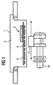
- a sensor is based on one Coil assembly 20, which together with an integrated electronic Evaluation circuit 21, z. B. in the form of an ASIC module, is housed in a sensor housing 22 (FIG 2).
- FIG. 3 shows a possible output signal from the PLCD as a function of the position of the selector slide 10.
- the output of the sensor element can be designed as a redundant differential interface. In addition to an output voltage signal U A, this results in a complementary signal U AK . Malfunctions of the PLCD can be identified by comparing the output voltage signal U A with the complementary signal U AK .
- the linear voltage signal can also be converted into discrete output values within the PLCD by an A / D converter integrated in the PLCD module.
- the output of the sensor element is then designed as a serial interface or bus interface.
- a step S1 it is checked continuously or periodically whether the position of the selector lever and thus the selector slide was changed ( Figure 5). Will a change determined, it is checked in steps S2 and S3 whether the selector lever is in one of the P or D selection ranges. For this purpose, the output voltage of the position detection sensor with lower and upper voltage limits of the Selection ranges P and D compared. It turns out that the Selector lever is in one of the selection ranges P or D, so in steps S4 and S5 the driving conditions of each Checked dialing range. While in the selection area D For example, it is checked whether the vehicle speed is above a specified limit, is in the dialing range P ensures that both the vehicle speed as well as the engine speed are zero.
- the selection ranges R and N can be determined according to the previously described method. Possible inaccuracies due to the calculation of Selection ranges (step S10) are thereby eliminated.
Landscapes
- Engineering & Computer Science (AREA)
- General Engineering & Computer Science (AREA)
- Mechanical Engineering (AREA)
- Control Of Transmission Device (AREA)
Abstract
Description
- Figur 1
- eine schematische Darstellung eines Steuergerätes mit Mitteln zur Positionserfassung,
- Figur 2
- eine Schrägansicht eines Positionserkennungssensors mit PLCD-Sensorelementen,
- Figur 3
- eine Kennlinie des Ausgangssignals des PLCD-Sensorelements,
- Figur 4
- eine schematische Darstellung der Wählbereiche eines Positionserkennungssensors und
- Figur 5
- ein Flußdiagramm des erfindungsgemäßen Selbstlernalgorithmus.
Claims (8)
- Elektronisches Steuergerät für ein Kraftfahrzeug-Automatikgetriebe miteinem flüssigkeitsdichten Gehäuse (1),einer im Gehäuse (1) untergebrachten Steuerelektronik (4),einem Positionserkennungssensor (5) zum Erfassen der Position eines Wählschiebers (10), wobei der Positionserkennungssensor (5)ein analoges, von der Position des Wählschiebers (10) abhängiges Ausgangssignal (UA) liefert undwährend des Betriebs im Kraftfahrzeug in der Steuerelektronik (4) mit Hilfe eines Selbstlernalgorithmus dynamisch abgeglichen wird.
- Steuergerät nach Anspruch 1, dadurch gekennzeichnet, daß ein Gebermagnet (11) unmittelbar auf dem Wählschieber (10) angeordnet ist.
- Steuergerät nach Anspruch 1 oder 2, dadurch gekennzeichnet, daß der Ausgang des Positionserkennungssensors (5) als redundante Differenzschnittstelle ausgeführt ist.
- Steuergerät nach Anspruch 1 oder 2, dadurch gekennzeichnet, daß das analoge Ausgangssignal (UA) innerhalb des Positionserkennungssensors (5) in diskrete Ausgangswerte umgesetzt wird und der Ausgang des Positionserkennungssensors (5) als serielle Schnittstelle oder Busschnittstelle ausgeführt ist.
- Steuergerät nach einem der vorhergehenden Ansprüche, dadurch gekennzeichnet, daß der Positionserkennungssensor (5) als PLCD (permanentmagnetic linear contactless displacementsensor) ausgebildet ist.
- Verfahren zum Abgleichen eines Positionserkennungssensors (5), der abhängig von der Position eines Wählschiebers (10) ein analoges Ausgangssignal liefert,bei dem überprüft wird, ob die Position des Wählschiebers (10) verändert wurde,bei dem geprüft wird, ob sich der Wählschieber (10) im Falle einer Positionsveränderung in einem von mindestens zwei vorgegebenen Wählbereichen (P, D) befindet,bei dem der Signalpegel des Ausgangssignals des Positionserkennungssensors (5) in einem Speicher abgelegt wird, falls sich der Wählschieber (10) in einem der vorgegebenen Wählbereiche (P, D) befindet,bei dem auf Basis der gespeicherten Signalpegel aktualisierte Signalpegel-Bänder für die jeweiligen Wählbereiche (P, D) bestimmt werden undbei dem auf Basis der gespeicherten Signalpegel Signalpegel-Bänder für die übrigen Wählbereiche (R, N) des Wählschiebers (10) berechnet werden und die korrespondierenden Signalpegel ebenfalls in einem Speicher abgelegt werden.
- Verfahren nach Anspruch 4, dadurch gekennzeichnet, daß der Signalpegel des Ausgangssignals des Positionserkennungssensors (5) nur dann in einem Speicher abgelegt wird, wenn vorgegebene Fahrbedingungen des jeweiligen Wählbereichs erfüllt sind.
- Verfahren nach Anspruch 4, dadurch gekennzeichnet, daß der Signalpegel des Ausgangssignals des Positionserkennungssensors (5) nur dann in einem Speicher abgelegt wird, wenn der Signalpegel für plausibel gehalten wird.
Applications Claiming Priority (3)
| Application Number | Priority Date | Filing Date | Title |
|---|---|---|---|
| DE19917873 | 1999-04-20 | ||
| DE19917873 | 1999-04-20 | ||
| US09/553,324 US6351699B1 (en) | 1999-04-20 | 2000-04-20 | Electronic control unit for an automatic transmission of a motor vehicle and method for adjusting a position detection sensor in the automatic transmission of the motor vehicle |
Publications (3)
| Publication Number | Publication Date |
|---|---|
| EP1046839A2 true EP1046839A2 (de) | 2000-10-25 |
| EP1046839A3 EP1046839A3 (de) | 2001-01-17 |
| EP1046839B1 EP1046839B1 (de) | 2003-07-16 |
Family
ID=26052995
Family Applications (1)
| Application Number | Title | Priority Date | Filing Date |
|---|---|---|---|
| EP00108563A Expired - Lifetime EP1046839B1 (de) | 1999-04-20 | 2000-04-19 | Verfahren zum Abgleichen eines Positionserkennungssensors |
Country Status (2)
| Country | Link |
|---|---|
| US (1) | US6351699B1 (de) |
| EP (1) | EP1046839B1 (de) |
Cited By (5)
| Publication number | Priority date | Publication date | Assignee | Title |
|---|---|---|---|---|
| WO2001013011A1 (de) * | 1999-08-12 | 2001-02-22 | Siemens Aktiengesellschaft | Elektronisches steuergerät für ein kraftfahrzeug-automatikgetriebe und verfahren zum abgleichen eines positionserkennungssensors in einem elektronischen steuergerät für ein kraftfahrzeug-automatikgetriebe |
| WO2003081088A1 (de) * | 2002-03-26 | 2003-10-02 | ZF Lemförder Metallwaren AG | Schaltvorrichtung zur steuerung der gangwahl eines kraftfahrzeuggetriebes |
| EP1132655B1 (de) * | 2000-03-10 | 2004-07-21 | Niles Parts Co., Ltd. | Schalteranordnung für den Wählschieber eines automatischen Getriebes |
| WO2019114521A1 (zh) * | 2017-12-13 | 2019-06-20 | 湖南中车时代电动汽车股份有限公司 | 一种确定atm变速箱各档位位置的方法、系统及相关装置 |
| CN110891819A (zh) * | 2017-05-01 | 2020-03-17 | Ghsp公司 | 带经训练的档位设定点的变速箱换档器 |
Families Citing this family (9)
| Publication number | Priority date | Publication date | Assignee | Title |
|---|---|---|---|---|
| US20030030210A1 (en) * | 2001-08-09 | 2003-02-13 | De La Rue Cash Systems Ab | Document feed out service |
| JP4356353B2 (ja) * | 2002-12-27 | 2009-11-04 | アイシン・エィ・ダブリュ株式会社 | ポジション判断装置、ポジション判断方法及びプログラム |
| DE102010029376B4 (de) * | 2010-05-27 | 2023-01-26 | Zf Friedrichshafen Ag | Getriebesteuermodul |
| CN103195924B (zh) * | 2013-04-28 | 2016-02-24 | 长城汽车股份有限公司 | 接触式挡位传感器及相应的换挡机构与汽车 |
| CN104595474B (zh) * | 2014-11-27 | 2018-02-13 | 盛瑞传动股份有限公司 | 自动变速器控制单元档位自学习控制方法和装置 |
| DE102016103217A1 (de) | 2015-02-26 | 2016-09-01 | Robert Bosch Gmbh | ECM und Verfahren zum Erlernen und Anpassen variierender Gangpositionen |
| CN106641231B (zh) * | 2017-01-18 | 2018-09-14 | 广州汽车集团股份有限公司 | 线控换挡器挡位自学习方法、系统以及线控换挡器系统 |
| JP7192247B2 (ja) * | 2018-05-17 | 2022-12-20 | 株式会社デンソー | 位置検出装置 |
| CN117329293A (zh) * | 2023-10-17 | 2024-01-02 | 南京美均电子科技有限公司 | 基于霍尔传感器的换挡器自学习方法、装置、设备及存储介质 |
Family Cites Families (11)
| Publication number | Priority date | Publication date | Assignee | Title |
|---|---|---|---|---|
| GB2156994B (en) | 1984-04-06 | 1987-04-08 | Emhart Ind | Method of monitoring the position of an operating member |
| DE3443176C1 (de) * | 1984-11-27 | 1990-11-15 | Angewandte Digital Elektronik Gmbh, 2051 Brunstorf | Verfahren zur Kalibrierung eines elektronischen Positionsgebers |
| DE3836145C2 (de) | 1988-10-22 | 1997-06-05 | Fichtel & Sachs Ag | Anordnung zur Erfassung der Stellung eines Maschinenteils, insbesondere eines Gangschalthebels |
| DE4340917C2 (de) * | 1993-12-01 | 1996-09-19 | Kostal Leopold Gmbh & Co Kg | Elektrische Schaltungsanordnung |
| US5621317A (en) * | 1994-12-12 | 1997-04-15 | Ford Motor Company | Position sensor with a magnetic proximity switch mechanism |
| CA2180863A1 (en) * | 1995-08-03 | 1997-02-04 | Charles Osborn | Vehicle shifter |
| DE19603197C1 (de) * | 1996-01-30 | 1997-02-27 | Kostal Leopold Gmbh & Co Kg | Elektrischer Signalgeber |
| DE19604948A1 (de) * | 1996-02-10 | 1997-08-14 | Telefunken Microelectron | Steuerungsanordnung für ein automatisches elektrohydraulisch gesteuertes Getriebe |
| US5867092A (en) * | 1996-08-30 | 1999-02-02 | Borg-Warner Automotive, Inc. | Hall effect transfer case shift mechanism position sensor |
| JP3478029B2 (ja) * | 1996-11-22 | 2003-12-10 | アイシン・エィ・ダブリュ株式会社 | 自動変速機用位置検出スイッチ一体型電子制御ユニット |
| US6000296A (en) * | 1998-03-30 | 1999-12-14 | Chrysler Corporation | Gated selector lever and controls for automatic transmission and transfer case |
-
2000
- 2000-04-19 EP EP00108563A patent/EP1046839B1/de not_active Expired - Lifetime
- 2000-04-20 US US09/553,324 patent/US6351699B1/en not_active Expired - Fee Related
Non-Patent Citations (1)
| Title |
|---|
| None |
Cited By (9)
| Publication number | Priority date | Publication date | Assignee | Title |
|---|---|---|---|---|
| WO2001013011A1 (de) * | 1999-08-12 | 2001-02-22 | Siemens Aktiengesellschaft | Elektronisches steuergerät für ein kraftfahrzeug-automatikgetriebe und verfahren zum abgleichen eines positionserkennungssensors in einem elektronischen steuergerät für ein kraftfahrzeug-automatikgetriebe |
| JP2003507670A (ja) * | 1999-08-12 | 2003-02-25 | シーメンス アクチエンゲゼルシヤフト | 自動車オートマチックトランスミッション用の電子制御装置、及び自動車オートマチックトランスミッション用の電子制御装置内の位置識別センサを調整するための方法 |
| US6717417B2 (en) | 1999-08-12 | 2004-04-06 | Siemens Aktiengesellschaft | Electronic controller for a motor vehicle automatic transmission and method for calibrating a position detection sensor in an electronic controller for a motor vehicle automatic transmission |
| EP1132655B1 (de) * | 2000-03-10 | 2004-07-21 | Niles Parts Co., Ltd. | Schalteranordnung für den Wählschieber eines automatischen Getriebes |
| WO2003081088A1 (de) * | 2002-03-26 | 2003-10-02 | ZF Lemförder Metallwaren AG | Schaltvorrichtung zur steuerung der gangwahl eines kraftfahrzeuggetriebes |
| US7334496B2 (en) | 2002-03-26 | 2008-02-26 | ZF Lemförder Metallwaren AG | Gearshift device for controlling the gear selection of a motor vehicle gearbox |
| CN110891819A (zh) * | 2017-05-01 | 2020-03-17 | Ghsp公司 | 带经训练的档位设定点的变速箱换档器 |
| EP3619072A4 (de) * | 2017-05-01 | 2021-01-06 | Ghsp, Inc. | Getriebeschaltvorrichtung mit trainierten gangpositionssollwerten |
| WO2019114521A1 (zh) * | 2017-12-13 | 2019-06-20 | 湖南中车时代电动汽车股份有限公司 | 一种确定atm变速箱各档位位置的方法、系统及相关装置 |
Also Published As
| Publication number | Publication date |
|---|---|
| EP1046839B1 (de) | 2003-07-16 |
| US6351699B1 (en) | 2002-02-26 |
| EP1046839A3 (de) | 2001-01-17 |
Similar Documents
| Publication | Publication Date | Title |
|---|---|---|
| EP1277003A1 (de) | Elektronisches steuergerät für ein kraftfahrzeug-automatikgetriebe und verfahren zum abgleichen eines positionserkennungssensors | |
| EP1046839B1 (de) | Verfahren zum Abgleichen eines Positionserkennungssensors | |
| EP2304274B1 (de) | Verfahren zum kalibrieren eines positionssensors in einem kraftfahrzeuggetriebe | |
| DE102007032139A1 (de) | Steuervorrichtung mit Positionssensor | |
| EP1259748B1 (de) | Elektromechanische verstelleinheit für ein getriebe | |
| DE4331909A1 (de) | Drehwinkelgeber | |
| DE102006008157A1 (de) | Magnetischer Sensor | |
| EP1105740B1 (de) | Elektronische sensoranordnung | |
| EP1884749A1 (de) | Induktive Positions- oder Winkelmesseinrichtung | |
| EP2160527B1 (de) | Vorrichtung zum erfassen von schaltstellungen | |
| DE102008048506B4 (de) | Verfahren und Vorrichtung zum Kalibrieren eines Sensors, Verfahren und System zum Bestimmen einer Einstellposition einer Schaltwelle eines Getriebes und Sensor zum Erfassen einer Einstellposition einer Schaltwelle eines Getriebes | |
| EP1910713B1 (de) | Stellvorrichtung für ein getriebe | |
| WO2010046218A1 (de) | Sensorschalteinheit | |
| WO2007025894A2 (de) | Positionssensor und verfahren zum betreiben eines positionssensors | |
| DE102008004916A1 (de) | Verfahren zur Kalibrierung der Position eines Magnetfeldsensors | |
| DE19837824A1 (de) | Zeigerinstrument mit Zeigerpositionsabgleichfunktion | |
| DE4340917C2 (de) | Elektrische Schaltungsanordnung | |
| DE102004001592B4 (de) | Drehdrückschalter und Feldgerät mit einem solchen | |
| EP2656364B1 (de) | Schaltvorrichtung mit schaltzustandserkennung | |
| EP0443148A1 (de) | Stellungsgeber | |
| DE102013200658A1 (de) | Schaltvorrichtung für ein Zahnräderwechselgetriebe eines Kraftfahrzeugs | |
| DE102008053196A1 (de) | Sensorschalteinheit | |
| DE102009049220A1 (de) | Sensorvorrichtung und Verfahren zur Erfassung der Position eines in mindestens zwei Richtungen verschiebbaren Hebels, insbesondere Getriebewählhebels in einem Kraftfahrzeug | |
| EP1887322A1 (de) | Induktive Positions- oder Winkelmesseinrichtung | |
| DE10225014A1 (de) | Wählhebelmodul für ein Kraftfahrzeug |
Legal Events
| Date | Code | Title | Description |
|---|---|---|---|
| PUAI | Public reference made under article 153(3) epc to a published international application that has entered the european phase |
Free format text: ORIGINAL CODE: 0009012 |
|
| AK | Designated contracting states |
Kind code of ref document: A2 Designated state(s): DE FR GB IT |
|
| AX | Request for extension of the european patent |
Free format text: AL;LT;LV;MK;RO;SI |
|
| PUAL | Search report despatched |
Free format text: ORIGINAL CODE: 0009013 |
|
| AK | Designated contracting states |
Kind code of ref document: A3 Designated state(s): AT BE CH CY DE DK ES FI FR GB GR IE IT LI LU MC NL PT SE |
|
| AX | Request for extension of the european patent |
Free format text: AL;LT;LV;MK;RO;SI |
|
| RIC1 | Information provided on ipc code assigned before grant |
Free format text: 7F 16H 59/10 A |
|
| 17P | Request for examination filed |
Effective date: 20010205 |
|
| AKX | Designation fees paid |
Free format text: DE FR GB IT |
|
| 17Q | First examination report despatched |
Effective date: 20020529 |
|
| GRAH | Despatch of communication of intention to grant a patent |
Free format text: ORIGINAL CODE: EPIDOS IGRA |
|
| RTI1 | Title (correction) |
Free format text: METHOD FOR CALIBRATING OF A POSITION SENSOR |
|
| GRAH | Despatch of communication of intention to grant a patent |
Free format text: ORIGINAL CODE: EPIDOS IGRA |
|
| GRAA | (expected) grant |
Free format text: ORIGINAL CODE: 0009210 |
|
| AK | Designated contracting states |
Designated state(s): DE FR GB IT |
|
| PG25 | Lapsed in a contracting state [announced via postgrant information from national office to epo] |
Ref country code: IT Free format text: LAPSE BECAUSE OF FAILURE TO SUBMIT A TRANSLATION OF THE DESCRIPTION OR TO PAY THE FEE WITHIN THE PRE;WARNING: LAPSES OF ITALIAN PATENTS WITH EFFECTIVE DATE BEFORE 2007 MAY HAVE OCCURRED AT ANY TIME BEFORE 2007. THE CORRECT EFFECTIVE DATE MAY BE DIFFERENT FROM THE ONE RECORDED.SCRIBED TIME-LIMIT Effective date: 20030716 Ref country code: GB Free format text: LAPSE BECAUSE OF FAILURE TO SUBMIT A TRANSLATION OF THE DESCRIPTION OR TO PAY THE FEE WITHIN THE PRESCRIBED TIME-LIMIT Effective date: 20030716 |
|
| REG | Reference to a national code |
Ref country code: GB Ref legal event code: FG4D Free format text: NOT ENGLISH |
|
| REF | Corresponds to: |
Ref document number: 50002887 Country of ref document: DE Date of ref document: 20030821 Kind code of ref document: P |
|
| GBV | Gb: ep patent (uk) treated as always having been void in accordance with gb section 77(7)/1977 [no translation filed] |
Effective date: 20030716 |
|
| ET | Fr: translation filed | ||
| PLBE | No opposition filed within time limit |
Free format text: ORIGINAL CODE: 0009261 |
|
| STAA | Information on the status of an ep patent application or granted ep patent |
Free format text: STATUS: NO OPPOSITION FILED WITHIN TIME LIMIT |
|
| 26N | No opposition filed |
Effective date: 20040419 |
|
| REG | Reference to a national code |
Ref country code: FR Ref legal event code: TP |
|
| REG | Reference to a national code |
Ref country code: FR Ref legal event code: PLFP Year of fee payment: 17 |
|
| REG | Reference to a national code |
Ref country code: FR Ref legal event code: PLFP Year of fee payment: 18 |
|
| REG | Reference to a national code |
Ref country code: FR Ref legal event code: PLFP Year of fee payment: 19 |
|
| PGFP | Annual fee paid to national office [announced via postgrant information from national office to epo] |
Ref country code: FR Payment date: 20180420 Year of fee payment: 19 |
|
| PGFP | Annual fee paid to national office [announced via postgrant information from national office to epo] |
Ref country code: DE Payment date: 20190430 Year of fee payment: 20 |
|
| PG25 | Lapsed in a contracting state [announced via postgrant information from national office to epo] |
Ref country code: FR Free format text: LAPSE BECAUSE OF NON-PAYMENT OF DUE FEES Effective date: 20190430 |
|
| REG | Reference to a national code |
Ref country code: DE Ref legal event code: R071 Ref document number: 50002887 Country of ref document: DE |