EP1046863A1 - Procédé de nettoyage de la chambre de combustion et/ou des conduits de fumée d'une chaudière et dispositif associé - Google Patents
Procédé de nettoyage de la chambre de combustion et/ou des conduits de fumée d'une chaudière et dispositif associé Download PDFInfo
- Publication number
- EP1046863A1 EP1046863A1 EP00108521A EP00108521A EP1046863A1 EP 1046863 A1 EP1046863 A1 EP 1046863A1 EP 00108521 A EP00108521 A EP 00108521A EP 00108521 A EP00108521 A EP 00108521A EP 1046863 A1 EP1046863 A1 EP 1046863A1
- Authority
- EP
- European Patent Office
- Prior art keywords
- flue gas
- cleaning liquid
- pressure
- combustion chamber
- cleaning
- Prior art date
- Legal status (The legal status is an assumption and is not a legal conclusion. Google has not performed a legal analysis and makes no representation as to the accuracy of the status listed.)
- Granted
Links
- 238000004140 cleaning Methods 0.000 title claims abstract description 95
- 238000002485 combustion reaction Methods 0.000 title claims abstract description 94
- 238000000034 method Methods 0.000 title claims abstract description 23
- 239000007788 liquid Substances 0.000 claims abstract description 57
- 238000005507 spraying Methods 0.000 claims abstract description 3
- UGFAIRIUMAVXCW-UHFFFAOYSA-N Carbon monoxide Chemical compound [O+]#[C-] UGFAIRIUMAVXCW-UHFFFAOYSA-N 0.000 claims description 55
- 239000003546 flue gas Substances 0.000 claims description 55
- 206010022000 influenza Diseases 0.000 claims description 26
- 239000008399 tap water Substances 0.000 claims description 13
- 235000020679 tap water Nutrition 0.000 claims description 13
- 239000010802 sludge Substances 0.000 claims description 12
- 238000005260 corrosion Methods 0.000 claims description 11
- 239000003795 chemical substances by application Substances 0.000 claims description 9
- 239000012530 fluid Substances 0.000 claims description 6
- 239000010865 sewage Substances 0.000 claims description 4
- 239000002002 slurry Substances 0.000 claims description 2
- 238000007599 discharging Methods 0.000 claims 3
- 239000002351 wastewater Substances 0.000 claims 1
- 239000004071 soot Substances 0.000 description 7
- 238000010438 heat treatment Methods 0.000 description 5
- 239000003921 oil Substances 0.000 description 3
- 238000007789 sealing Methods 0.000 description 3
- XLYOFNOQVPJJNP-UHFFFAOYSA-N water Substances O XLYOFNOQVPJJNP-UHFFFAOYSA-N 0.000 description 3
- 230000007797 corrosion Effects 0.000 description 2
- 239000000428 dust Substances 0.000 description 2
- 239000007789 gas Substances 0.000 description 2
- 238000003780 insertion Methods 0.000 description 2
- 230000037431 insertion Effects 0.000 description 2
- 239000002245 particle Substances 0.000 description 2
- 230000002378 acidificating effect Effects 0.000 description 1
- 239000003245 coal Substances 0.000 description 1
- 150000001875 compounds Chemical class 0.000 description 1
- 230000009193 crawling Effects 0.000 description 1
- 239000003599 detergent Substances 0.000 description 1
- 238000005108 dry cleaning Methods 0.000 description 1
- 230000000694 effects Effects 0.000 description 1
- 239000002737 fuel gas Substances 0.000 description 1
- 239000000295 fuel oil Substances 0.000 description 1
- 231100000206 health hazard Toxicity 0.000 description 1
- 238000002663 nebulization Methods 0.000 description 1
- 238000004321 preservation Methods 0.000 description 1
- 230000002265 prevention Effects 0.000 description 1
- 239000011814 protection agent Substances 0.000 description 1
- 230000001105 regulatory effect Effects 0.000 description 1
- 239000000779 smoke Substances 0.000 description 1
- 239000004449 solid propellant Substances 0.000 description 1
- 239000007921 spray Substances 0.000 description 1
- 150000003464 sulfur compounds Chemical class 0.000 description 1
- 239000002023 wood Substances 0.000 description 1
Images


Classifications
-
- F—MECHANICAL ENGINEERING; LIGHTING; HEATING; WEAPONS; BLASTING
- F28—HEAT EXCHANGE IN GENERAL
- F28G—CLEANING OF INTERNAL OR EXTERNAL SURFACES OF HEAT-EXCHANGE OR HEAT-TRANSFER CONDUITS, e.g. WATER TUBES OR BOILERS
- F28G9/00—Cleaning by flushing or washing, e.g. with chemical solvents
-
- F—MECHANICAL ENGINEERING; LIGHTING; HEATING; WEAPONS; BLASTING
- F23—COMBUSTION APPARATUS; COMBUSTION PROCESSES
- F23J—REMOVAL OR TREATMENT OF COMBUSTION PRODUCTS OR COMBUSTION RESIDUES; FLUES
- F23J3/00—Removing solid residues from passages or chambers beyond the fire, e.g. from flues by soot blowers
Definitions
- the invention relates to a method for cleaning the Combustion chamber and / or the flue gas flues of a boiler from Combustion residues with one assigned to the combustion chamber Flame tube opening and one assigned to the flue gas flues Cleaning opening in the flue gas pipe and a device for this.
- Boiler residues When burning liquid or solid fuels, such as for example oil, wood or coal, in a combustion chamber Boiler residues always arise in the Combustion chamber and the subordinate flue gas ducts that come on the corresponding walls of the boiler and the must be removed from time to time so that efficiency the heating system due to the insulating effect the combustion residues did not deteriorate significantly.
- the sulfur compounds contain Corrosion in the combustion chamber and combustion residues the flue gas flues that cause the boiler to fail can.
- a method of cleaning the combustion chamber of a boiler discloses DE-C-31 42 364.
- household detergent dissolved in water using a garden sprayer in sprayed the combustion chamber.
- the solution is left at 50 ° C act for at least 10 minutes.
- the boiler is heated to 90 ° C, causing the water to evaporate and the residues detached by the warm fuel gases be removed from the boiler via the fireplace.
- the Removing and / or removing the residues is hereby, however not sufficiently ensured.
- DE-A-20 40 529 describes a method and a method Device for cleaning the combustion chamber of an oil heating system known, with a soot removal solution in the Fuel oil supply pipe is given to the oil heating system.
- the soot remover solution gets into the combustion chamber and causes there an intense soot-consuming flame, its acidic Exhaust gases make the soot deposits disappear. This procedure must be carried out to achieve adequate cleaning be repeated practically every month.
- a method for cleaning the Combustion chamber and / or the flue gas flues of a boiler from Combustion residues of the type mentioned and one To provide device for performing the method that or the one associated with a low workload allows thorough cleaning of the boiler, taking a Prevention of soot from the boiler is prevented.
- the method thus offers the possibility of the combustion chamber and / or the flue gas flues for cleaning or solving the Spray combustion residues and at the same time dissolve them Combustion residues and the cleaning liquid remove, reducing the amount of work involved in cleaning the Boiler is significantly reduced.
- a particularly effective one Cleaning of the combustion chamber and the flue gas flues is complete the simultaneous supply and discharge of the cleaning liquid and of the dissolved combustion residues both through the flame tube opening as well as ensured by the flue gas pipe.
- the use of a cleaning fluid as well, in particular the sealed insertion of both the pressure pipe and of the suction hose prevent soot from escaping from the Boiler during cleaning, which makes cleaning performing installer no health hazard is exposed.
- Cleaning liquid over at the free end of the pressure pipe arranged atomizer nozzles in the combustion chamber and / or Smoke gas flues nebulized.
- the nebulized cleaning liquid strikes on the walls of the combustion chamber and / or Flue gas pipes down and crawling into the combustion residues, thereby solving them.
- nebulized application of the cleaning liquid to the surfaces the combustion chamber and / or the flue gas flues and sealing elements inside the boiler from damage due to pressurization or other mechanical Protected by the cleaning liquid.
- a cleaning liquid on an outlet valve tap water taken from a tap water network is used.
- the cleaning liquid is cleaned using a Low pressure pump removed from a storage container.
- the dissolved combustion residues in a sewage network pumped.
- the dissolved combustion residues into a separator Pumped sludge tank In places where the introduction of combustion residues in a sewage network is not permitted can be disposed of in the sludge container collected and transported away.
- the device thus provides a small amount of work Boiler cleaning system to be installed represents the introduction of cleaning fluid the pressure pipe and the simultaneous discharge of the cleaning liquid as well as the dissolved combustion residues by means of of the suction hose.
- both Pressure pipe and the suction hose sealed in the am Boiler existing flame tube opening and / or the flue gas pipe soot is used to escape the soot Boiler prevented during cleaning.
- the flame tube opening and / or the flue gas tube an elastic cuff for sealed reception of the pressure pipe and the suction hose.
- the elastic cuff inside a bladder to be inflated.
- the bladder connected to a pump.
- the pump is designed as a palm pump.
- the cuff is largely exposed to the air Dimensions of the flame tube opening and / or the flue gas tube and the diameter of the pressure pipe and the suction hose adapt, which ensures the mutual sealing is.
- the atomizer nozzle causes nebulization in the boiler cleaning liquid to be entered.
- the Atomizer nozzle is spherical.
- the cleaning liquid is preferably tap water and the pressure pipe stands over a pressure hose with an outlet valve a tap water network in connection.
- This Inexpensive embodiment of the invention enables Use of the in most boiler rooms for filling the heating system already existing outlet valve of Tap water network to provide the cleaning liquid.
- the pressure tube is preferably flexible and in itself its length variable.
- the suction hose is preferably flexible in itself and in its Variable length.
- the Suction hose in the in the flame tube opening and / or that Flue gas pipe used area on its top one leaf spring angled downwards.
- the suction hose carries at which in the flame tube opening and / or that Flue gas pipe inserted end a weight.
- the suction hose is preferably used to discharge the cleaning liquid and the dissolved combustion residues with a sewer connection.
- a sewer connection is for draining the heating system in in most cases in the vicinity of the boiler.
- the suction hose for draining the cleaning liquid and the dissolved combustion residues with coupled to at least one separator. It is expedient at least one of the separators connected to a sludge tank. This makes it easier to collect during cleaning residues and their disposal given.
- a pump is provided in the sludge tank.
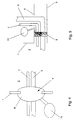
- the boiler 1 comprises a combustion chamber 2 with flue gas flues 3 and a flame tube opening 4 assigned to the combustion chamber 2 and a flue gas pipe 5 assigned to the flue gas flues 3.
- a flue gas pipe 5 assigned to the flue gas flues 3.
- In the flue gas pipe 5 is a cleaning opening in the area of the boiler 1 6 embedded.
- the cuff 9 has a bladder inside on that to inflate air with a palm pump 10 communicates.
- a cleaning liquid 11 in the form of tap water is the pressure pipe 7 via a pressure hose 12 with an outlet valve 12 of a tap water network in connection.
- a valve 14 is arranged to the supply of the cleaning liquid 11 to regulate.
- the discharge of the cleaning liquid from the pressure pipe 7 into the combustion chamber 2 via a spherical atomizing nozzle 15 which on the End of the pressure tube is arranged, which is in the combustion chamber 2 is located.
- the pressure pipe 7 is flexible and variable in length.
- the suction hose 8 is on a suction pump 16 is connected, the suction hose 8 in the further course of a wash basin 17 with a sewer network 18 communicates.
- the flexible sewage hose 8 bears on his inserted into the flame tube opening 4 Area on its top a leaf spring 36.
- the Leaf spring 36 causes the free end of the suction hose 8 pressed towards the bottom of the combustion chamber 2 is where the suction hose 8 the dissolved combustion residue records.
- the pressure pipe 7 and the suction hose 8 can be targeted Cleaning the flue gas flues 3 according to FIGS. 2 and 5 insert through the cleaning opening 6 into the flue gas pipe 5.
- pressure hose 12 is a three-way valve 19 used to which a reservoir 20 for an anti-corrosion agent is connected, the supply of the anti-corrosion agent and shutting off the supply at the same time the cleaning liquid 11 by switching accordingly of the three-way valve 19 is ensured.
- the Cleaning liquid 11 removed from a storage container 21, the one with an upper-side filling opening 22 and an underside Drain opening 23 for the cleaning liquid 11 is provided, wherein the drain opening 23 is a shut-off valve 24 is assigned.
- the one inserted into the reservoir 21 Pressure hose 12 carries one at its free end Filter 25, which is the entry of particles from the reservoir 21 or the cleaning liquid 11 in the pressure hose 12 prevented.
- the three-way valve 19 inserted into the pressure hose 12.
- the pressure hose 12 is connected to a low pressure pump 26.
- the regulation of the supply of the cleaning liquid 11 or the anti-corrosion agent is carried out by means of the Pressure hose 12 with valve 14 connecting pressure pipe 7.
- Vacuum is a coupled to a vacuum pump 38 Wind boiler 27 provided. This is via a pipeline 28, which is provided with an air filter 29, with a first Separator 30 and a second separator 31 coupled, the suction hose 8 being connected to the second separator 31 connected.
- a pipeline 28 which is provided with an air filter 29, with a first Separator 30 and a second separator 31 coupled, the suction hose 8 being connected to the second separator 31 connected.
- the one that occurs here Splash water is separated in the first separator 30, so that the vacuum pump connected to the air boiler 27 through the air filter 29 sucks in cleaned air.
- the one in the two Separators 30, 31 accumulated residues are over a Pipeline 32 by means of a sludge pump 33 a sludge tank 34 fed.
- a shut-off valve 35 arranged in the pipe 32 in the pipe 32 is between the first separator 30 and the sludge pump 22 .
- the sludge container 24 is emptied via a shut-off valve 37 in the bottom area of the sludge tank 34 is arranged.
- the other end of the Suction hose 8 is in a sink 17 with a sewer connection 18 hung and the pressure pipe 7 is coupled to the pressure hose 12 via the closed valve 14, the to the outlet valve 13 of the tap water network connected. If necessary, the pressure pipe 7 or a pressure reducing valve can be assigned to the pressure hose 12.
- the suction pump 16 is switched on and the dissolved and combustion residues accumulated on the bottom of the combustion chamber 2 are absorbed by the suction hose 8 and fed to the sewer network via the sewer connection 18. Entering the cleaning liquid and vacuuming the Combustion residues occur simultaneously until the Combustion chamber 2 of the boiler 1 completely from combustion residues is exempted, the inflow of the cleaning liquid 11 can be regulated with the valve 14. While due to the cleaning liquid 11, which binds the dissolved combustion residues, and the sealed Arrangement of the pressure pipe 7 and the suction hose 8 no dust can escape from the combustion chamber 2.
- the outlet valve 13 are closed and the suction hose 8 the dissolved combustion residues still remaining in the combustion chamber 2 as well as the remaining cleaning liquid 11 sucked off.
- the suction pump 16 is then switched off and the compressed air is removed from the cuff 9.
- the cuff 9 together with the pressure pipe 7 and the suction hose 8 of the flame tube opening 4 can be removed.
Landscapes
- Engineering & Computer Science (AREA)
- Mechanical Engineering (AREA)
- General Engineering & Computer Science (AREA)
- Chemical & Material Sciences (AREA)
- Combustion & Propulsion (AREA)
- Incineration Of Waste (AREA)
- Treating Waste Gases (AREA)
- Cleaning In General (AREA)
- Cleaning By Liquid Or Steam (AREA)
Applications Claiming Priority (2)
| Application Number | Priority Date | Filing Date | Title |
|---|---|---|---|
| DE19918103 | 1999-04-22 | ||
| DE19918103A DE19918103C2 (de) | 1999-04-22 | 1999-04-22 | Vorrichtung zum Reinigen der Brennkammer und/oder der Rauchgaszüge eines Heizkessels |
Publications (2)
| Publication Number | Publication Date |
|---|---|
| EP1046863A1 true EP1046863A1 (fr) | 2000-10-25 |
| EP1046863B1 EP1046863B1 (fr) | 2004-09-01 |
Family
ID=7905365
Family Applications (1)
| Application Number | Title | Priority Date | Filing Date |
|---|---|---|---|
| EP00108521A Expired - Lifetime EP1046863B1 (fr) | 1999-04-22 | 2000-04-19 | Dispositif pour le nettoyage d'une chambre de combustion et/ou des conduits de fumée d'une chaudière |
Country Status (3)
| Country | Link |
|---|---|
| EP (1) | EP1046863B1 (fr) |
| AT (1) | ATE275257T1 (fr) |
| DE (2) | DE19918103C2 (fr) |
Families Citing this family (2)
| Publication number | Priority date | Publication date | Assignee | Title |
|---|---|---|---|---|
| DE102008022696A1 (de) | 2008-05-07 | 2009-11-12 | Solvis Gmbh & Co. Kg | Feuerungseinrichtung mit einer Reinigungseinrichtung |
| CN110280118B (zh) * | 2019-06-18 | 2024-02-13 | 华电电力科学研究院有限公司 | 一种电站锅炉烟气净化处理装置及其工作方法 |
Citations (7)
| Publication number | Priority date | Publication date | Assignee | Title |
|---|---|---|---|---|
| US2601041A (en) * | 1949-06-11 | 1952-06-17 | Gilbert & Barker Mfg Co | Controlling mechanism for flue cleaning means for heating apparatus |
| DE2040529A1 (de) | 1970-08-14 | 1972-02-17 | Illbruck Hans Peter | Verfahren und Vorrichtung zum Reinigen des Verbrennungsraums von zentralen OElheizungsoefen |
| DE2645938A1 (de) * | 1976-10-12 | 1978-04-13 | Giancarlo Bettella | Verfahren und vorrichtung fuer die reinigung und die beseitigung von verbrennungsrueckstaenden insbesondere bei heizkesselrohren |
| DE3106421A1 (de) * | 1981-02-20 | 1982-11-11 | Steag Ag, 4300 Essen | Verfahren zur reinigung des flammrohres eines mindestens mit einem flammrohr versehenen kessels und einrichtung zur durchfuehrung des verfahrens |
| DE3142364C1 (de) | 1981-10-26 | 1983-03-10 | Bernd Burger | Verfahren zum Reinigen des Brennraumes einer Heizungsanlage |
| EP0195366A2 (fr) * | 1985-03-14 | 1986-09-24 | METASCO Chemische-Technische Produkte GmbH | Procédé et dispositif pour le nettoyage des conduits de fumée |
| FR2705825A1 (fr) * | 1993-05-28 | 1994-12-02 | Framatome Sa | Dispositif de décontamination de la surface interne d'un tronçon d'extrémité d'une canalisation. |
Family Cites Families (2)
| Publication number | Priority date | Publication date | Assignee | Title |
|---|---|---|---|---|
| DE8304427U1 (de) * | 1983-06-09 | Seele, Wilfried, 4005 Meerbusch | Dichtungspackung für Hochtemperaturventile und Rußbläser | |
| DE1848991U (de) * | 1961-12-22 | 1962-03-29 | Hans Mettauer | Vorrichtung zur kesselreinigung. |
-
1999
- 1999-04-22 DE DE19918103A patent/DE19918103C2/de not_active Expired - Fee Related
-
2000
- 2000-04-19 AT AT00108521T patent/ATE275257T1/de active
- 2000-04-19 EP EP00108521A patent/EP1046863B1/fr not_active Expired - Lifetime
- 2000-04-19 DE DE50007584T patent/DE50007584D1/de not_active Expired - Lifetime
Patent Citations (7)
| Publication number | Priority date | Publication date | Assignee | Title |
|---|---|---|---|---|
| US2601041A (en) * | 1949-06-11 | 1952-06-17 | Gilbert & Barker Mfg Co | Controlling mechanism for flue cleaning means for heating apparatus |
| DE2040529A1 (de) | 1970-08-14 | 1972-02-17 | Illbruck Hans Peter | Verfahren und Vorrichtung zum Reinigen des Verbrennungsraums von zentralen OElheizungsoefen |
| DE2645938A1 (de) * | 1976-10-12 | 1978-04-13 | Giancarlo Bettella | Verfahren und vorrichtung fuer die reinigung und die beseitigung von verbrennungsrueckstaenden insbesondere bei heizkesselrohren |
| DE3106421A1 (de) * | 1981-02-20 | 1982-11-11 | Steag Ag, 4300 Essen | Verfahren zur reinigung des flammrohres eines mindestens mit einem flammrohr versehenen kessels und einrichtung zur durchfuehrung des verfahrens |
| DE3142364C1 (de) | 1981-10-26 | 1983-03-10 | Bernd Burger | Verfahren zum Reinigen des Brennraumes einer Heizungsanlage |
| EP0195366A2 (fr) * | 1985-03-14 | 1986-09-24 | METASCO Chemische-Technische Produkte GmbH | Procédé et dispositif pour le nettoyage des conduits de fumée |
| FR2705825A1 (fr) * | 1993-05-28 | 1994-12-02 | Framatome Sa | Dispositif de décontamination de la surface interne d'un tronçon d'extrémité d'une canalisation. |
Also Published As
| Publication number | Publication date |
|---|---|
| EP1046863B1 (fr) | 2004-09-01 |
| ATE275257T1 (de) | 2004-09-15 |
| DE19918103A1 (de) | 2000-11-30 |
| DE19918103C2 (de) | 2001-03-29 |
| DE50007584D1 (de) | 2004-10-07 |
Similar Documents
| Publication | Publication Date | Title |
|---|---|---|
| DE19637086C2 (de) | Automatisch arbeitende Reinigungsanlage für Werkstücke | |
| DE19508488C3 (de) | Verfahren und Vorrichtung zum Erzeugen von deponiefähigen oder weiterverarbeitbaren Verbrennungsrückständen aus einer Abfallverbrennungsanlage | |
| DE202004003494U1 (de) | Reinigungsgerät für Räumlichkeiten und deren Atmosphäre | |
| EP1046863B1 (fr) | Dispositif pour le nettoyage d'une chambre de combustion et/ou des conduits de fumée d'une chaudière | |
| EP2867585B1 (fr) | Procédé permettant de faire fonctionner un système d'évacuation d'air et système d'évacuation d'air destiné à une cuisine | |
| DE102008008066A1 (de) | Bodenreinigungsgerät | |
| DE4426708A1 (de) | Verfahren und Vorrichtung zur Reinigung von Entsorgungsschächten | |
| DE19915413B4 (de) | Düsenkörper für ein Reinigungsgerät | |
| DE19701010A1 (de) | Verfahren zur Sanierung der Innenwände festverlegter Rohrleitungen | |
| DE29615431U1 (de) | Mobile Vorrichtung zur Abfallbehälterreinigung | |
| DE2645938A1 (de) | Verfahren und vorrichtung fuer die reinigung und die beseitigung von verbrennungsrueckstaenden insbesondere bei heizkesselrohren | |
| AT517177B1 (de) | Einrichtung zur Reinigung und dazugehöriges Verfahren von offenen und geschlossenen Fluidsystemen insbesondere Brunnenanlagen, Rohrleitungen und Boilern mittels eines Kavitationsdüsensystems | |
| DE29918054U1 (de) | Vorrichtung zur Brennkammerreinigung | |
| CH662406A5 (en) | Spraying device | |
| DE3923460C2 (fr) | ||
| DD284616A5 (de) | Verfahren und vorrichtung zur thermischen rohrinnenreinigung | |
| EP1295585B1 (fr) | Méthode et dispositif pour la desinfection de la tuyauterie de baignoires tourbillonnantes | |
| DE3720846C2 (de) | Vorrichtung zur Konservierung anatomischer Präparate | |
| DE9422002U1 (de) | Vorrichtung zur Reinigung von Entsorgungsschächten | |
| US3415231A (en) | Method for removing soot from boiler tubes and apparatus therefor | |
| DE4112914A1 (de) | Verfahren und vorrichtung zum regenerieren schadstoffbelasteter teile | |
| DE2216086A1 (de) | Verfahren und Vorrichtung zum Reinigen der Innenwand lotrechter Schachte | |
| EP0527543A1 (fr) | Procédé et dispositif pour le nettoyage des foiles filtrantes | |
| DE3820847C2 (fr) | ||
| DE102023114218A1 (de) | Spüldämpfer |
Legal Events
| Date | Code | Title | Description |
|---|---|---|---|
| PUAI | Public reference made under article 153(3) epc to a published international application that has entered the european phase |
Free format text: ORIGINAL CODE: 0009012 |
|
| AK | Designated contracting states |
Kind code of ref document: A1 Designated state(s): AT CH DE FR GB IT LI NL |
|
| AX | Request for extension of the european patent |
Free format text: AL;LT;LV;MK;RO;SI |
|
| 17P | Request for examination filed |
Effective date: 20010414 |
|
| AKX | Designation fees paid |
Free format text: AT CH DE FR GB IT LI NL |
|
| 17Q | First examination report despatched |
Effective date: 20030813 |
|
| GRAP | Despatch of communication of intention to grant a patent |
Free format text: ORIGINAL CODE: EPIDOSNIGR1 |
|
| RTI1 | Title (correction) |
Free format text: DEVICE FOR CLEANING A COMBUSTION CHAMBER AND/OR EXHAUST GAS DUCTS OF A BOILER |
|
| GRAS | Grant fee paid |
Free format text: ORIGINAL CODE: EPIDOSNIGR3 |
|
| GRAA | (expected) grant |
Free format text: ORIGINAL CODE: 0009210 |
|
| AK | Designated contracting states |
Kind code of ref document: B1 Designated state(s): AT CH DE FR GB IT LI NL |
|
| PG25 | Lapsed in a contracting state [announced via postgrant information from national office to epo] |
Ref country code: IT Free format text: LAPSE BECAUSE OF FAILURE TO SUBMIT A TRANSLATION OF THE DESCRIPTION OR TO PAY THE FEE WITHIN THE PRESCRIBED TIME-LIMIT;WARNING: LAPSES OF ITALIAN PATENTS WITH EFFECTIVE DATE BEFORE 2007 MAY HAVE OCCURRED AT ANY TIME BEFORE 2007. THE CORRECT EFFECTIVE DATE MAY BE DIFFERENT FROM THE ONE RECORDED. Effective date: 20040901 Ref country code: NL Free format text: LAPSE BECAUSE OF FAILURE TO SUBMIT A TRANSLATION OF THE DESCRIPTION OR TO PAY THE FEE WITHIN THE PRESCRIBED TIME-LIMIT Effective date: 20040901 |
|
| REG | Reference to a national code |
Ref country code: GB Ref legal event code: FG4D Free format text: NOT ENGLISH |
|
| REG | Reference to a national code |
Ref country code: CH Ref legal event code: EP |
|
| REF | Corresponds to: |
Ref document number: 50007584 Country of ref document: DE Date of ref document: 20041007 Kind code of ref document: P |
|
| REG | Reference to a national code |
Ref country code: CH Ref legal event code: NV Representative=s name: PA ALDO ROEMPLER |
|
| GBT | Gb: translation of ep patent filed (gb section 77(6)(a)/1977) |
Effective date: 20050119 |
|
| NLV1 | Nl: lapsed or annulled due to failure to fulfill the requirements of art. 29p and 29m of the patents act | ||
| PLBE | No opposition filed within time limit |
Free format text: ORIGINAL CODE: 0009261 |
|
| STAA | Information on the status of an ep patent application or granted ep patent |
Free format text: STATUS: NO OPPOSITION FILED WITHIN TIME LIMIT |
|
| ET | Fr: translation filed | ||
| 26N | No opposition filed |
Effective date: 20050602 |
|
| REG | Reference to a national code |
Ref country code: CH Ref legal event code: PCAR Free format text: ALDO ROEMPLER PATENTANWALT;BRENDENWEG 11 POSTFACH 154;9424 RHEINECK (CH) |
|
| REG | Reference to a national code |
Ref country code: DE Ref legal event code: R082 Ref document number: 50007584 Country of ref document: DE Representative=s name: MUELLER, JOCHEN, DIPL.-ING., DE Ref country code: DE Ref legal event code: R082 Ref document number: 50007584 Country of ref document: DE Representative=s name: JOCHEN MUELLER, DE |
|
| PGFP | Annual fee paid to national office [announced via postgrant information from national office to epo] |
Ref country code: GB Payment date: 20140423 Year of fee payment: 15 |
|
| PGFP | Annual fee paid to national office [announced via postgrant information from national office to epo] |
Ref country code: FR Payment date: 20140416 Year of fee payment: 15 Ref country code: CH Payment date: 20140422 Year of fee payment: 15 Ref country code: AT Payment date: 20140417 Year of fee payment: 15 |
|
| REG | Reference to a national code |
Ref country code: AT Ref legal event code: MM01 Ref document number: 275257 Country of ref document: AT Kind code of ref document: T Effective date: 20140419 |
|
| PGFP | Annual fee paid to national office [announced via postgrant information from national office to epo] |
Ref country code: DE Payment date: 20150422 Year of fee payment: 16 |
|
| REG | Reference to a national code |
Ref country code: CH Ref legal event code: PL |
|
| GBPC | Gb: european patent ceased through non-payment of renewal fee |
Effective date: 20150419 |
|
| PG25 | Lapsed in a contracting state [announced via postgrant information from national office to epo] |
Ref country code: GB Free format text: LAPSE BECAUSE OF NON-PAYMENT OF DUE FEES Effective date: 20150419 Ref country code: CH Free format text: LAPSE BECAUSE OF NON-PAYMENT OF DUE FEES Effective date: 20150430 Ref country code: LI Free format text: LAPSE BECAUSE OF NON-PAYMENT OF DUE FEES Effective date: 20150430 |
|
| REG | Reference to a national code |
Ref country code: FR Ref legal event code: ST Effective date: 20151231 |
|
| PG25 | Lapsed in a contracting state [announced via postgrant information from national office to epo] |
Ref country code: FR Free format text: LAPSE BECAUSE OF NON-PAYMENT OF DUE FEES Effective date: 20150430 |
|
| PG25 | Lapsed in a contracting state [announced via postgrant information from national office to epo] |
Ref country code: AT Free format text: THE PATENT HAS BEEN ANNULLED BY A DECISION OF A NATIONAL AUTHORITY Effective date: 20140419 |
|
| REG | Reference to a national code |
Ref country code: DE Ref legal event code: R119 Ref document number: 50007584 Country of ref document: DE |
|
| PG25 | Lapsed in a contracting state [announced via postgrant information from national office to epo] |
Ref country code: DE Free format text: LAPSE BECAUSE OF NON-PAYMENT OF DUE FEES Effective date: 20161101 |