EP1046900A2 - Détection optique hétérodyne pour spectroscopie par abaisement de cavité d' anneau - Google Patents
Détection optique hétérodyne pour spectroscopie par abaisement de cavité d' anneau Download PDFInfo
- Publication number
- EP1046900A2 EP1046900A2 EP00300293A EP00300293A EP1046900A2 EP 1046900 A2 EP1046900 A2 EP 1046900A2 EP 00300293 A EP00300293 A EP 00300293A EP 00300293 A EP00300293 A EP 00300293A EP 1046900 A2 EP1046900 A2 EP 1046900A2
- Authority
- EP
- European Patent Office
- Prior art keywords
- ring
- wave
- signal
- cavity
- local oscillator
- Prior art date
- Legal status (The legal status is an assumption and is not a legal conclusion. Google has not performed a legal analysis and makes no representation as to the accuracy of the status listed.)
- Withdrawn
Links
- 238000001514 detection method Methods 0.000 title claims abstract description 41
- 230000003287 optical effect Effects 0.000 title claims abstract description 32
- 238000000180 cavity ring-down spectroscopy Methods 0.000 title abstract description 35
- 230000010287 polarization Effects 0.000 claims abstract description 65
- 230000035945 sensitivity Effects 0.000 description 22
- 238000010521 absorption reaction Methods 0.000 description 14
- 238000005259 measurement Methods 0.000 description 14
- 238000000034 method Methods 0.000 description 8
- 238000010586 diagram Methods 0.000 description 6
- 239000007789 gas Substances 0.000 description 4
- 238000000862 absorption spectrum Methods 0.000 description 3
- 238000013459 approach Methods 0.000 description 3
- 238000010009 beating Methods 0.000 description 3
- 230000008878 coupling Effects 0.000 description 3
- 238000010168 coupling process Methods 0.000 description 3
- 238000005859 coupling reaction Methods 0.000 description 3
- 230000007246 mechanism Effects 0.000 description 3
- 238000002310 reflectometry Methods 0.000 description 3
- 230000003595 spectral effect Effects 0.000 description 3
- 238000004611 spectroscopical analysis Methods 0.000 description 3
- 238000012935 Averaging Methods 0.000 description 2
- 230000003321 amplification Effects 0.000 description 2
- 230000005684 electric field Effects 0.000 description 2
- 230000005284 excitation Effects 0.000 description 2
- 238000001914 filtration Methods 0.000 description 2
- 238000003199 nucleic acid amplification method Methods 0.000 description 2
- XLYOFNOQVPJJNP-UHFFFAOYSA-N water Chemical compound O XLYOFNOQVPJJNP-UHFFFAOYSA-N 0.000 description 2
- 239000011358 absorbing material Substances 0.000 description 1
- 230000006978 adaptation Effects 0.000 description 1
- 230000004888 barrier function Effects 0.000 description 1
- 230000008901 benefit Effects 0.000 description 1
- 238000007796 conventional method Methods 0.000 description 1
- 230000007423 decrease Effects 0.000 description 1
- 230000001419 dependent effect Effects 0.000 description 1
- 230000000694 effects Effects 0.000 description 1
- 238000005516 engineering process Methods 0.000 description 1
- 238000012544 monitoring process Methods 0.000 description 1
- 230000000737 periodic effect Effects 0.000 description 1
- 230000008569 process Effects 0.000 description 1
- 238000012552 review Methods 0.000 description 1
- 238000000926 separation method Methods 0.000 description 1
- 238000007493 shaping process Methods 0.000 description 1
- 238000012306 spectroscopic technique Methods 0.000 description 1
- 238000001228 spectrum Methods 0.000 description 1
- 239000010409 thin film Substances 0.000 description 1
- 230000007704 transition Effects 0.000 description 1
Images



Classifications
-
- G—PHYSICS
- G01—MEASURING; TESTING
- G01N—INVESTIGATING OR ANALYSING MATERIALS BY DETERMINING THEIR CHEMICAL OR PHYSICAL PROPERTIES
- G01N21/00—Investigating or analysing materials by the use of optical means, i.e. using sub-millimetre waves, infrared, visible or ultraviolet light
- G01N21/17—Systems in which incident light is modified in accordance with the properties of the material investigated
- G01N21/25—Colour; Spectral properties, i.e. comparison of effect of material on the light at two or more different wavelengths or wavelength bands
- G01N21/31—Investigating relative effect of material at wavelengths characteristic of specific elements or molecules, e.g. atomic absorption spectrometry
- G01N21/39—Investigating relative effect of material at wavelengths characteristic of specific elements or molecules, e.g. atomic absorption spectrometry using tunable lasers
-
- G—PHYSICS
- G01—MEASURING; TESTING
- G01J—MEASUREMENT OF INTENSITY, VELOCITY, SPECTRAL CONTENT, POLARISATION, PHASE OR PULSE CHARACTERISTICS OF INFRARED, VISIBLE OR ULTRAVIOLET LIGHT; COLORIMETRY; RADIATION PYROMETRY
- G01J3/00—Spectrometry; Spectrophotometry; Monochromators; Measuring colours
- G01J3/28—Investigating the spectrum
- G01J3/30—Measuring the intensity of spectral lines directly on the spectrum itself
-
- G—PHYSICS
- G01—MEASURING; TESTING
- G01J—MEASUREMENT OF INTENSITY, VELOCITY, SPECTRAL CONTENT, POLARISATION, PHASE OR PULSE CHARACTERISTICS OF INFRARED, VISIBLE OR ULTRAVIOLET LIGHT; COLORIMETRY; RADIATION PYROMETRY
- G01J3/00—Spectrometry; Spectrophotometry; Monochromators; Measuring colours
- G01J3/28—Investigating the spectrum
- G01J3/42—Absorption spectrometry; Double beam spectrometry; Flicker spectrometry; Reflection spectrometry
-
- G—PHYSICS
- G01—MEASURING; TESTING
- G01N—INVESTIGATING OR ANALYSING MATERIALS BY DETERMINING THEIR CHEMICAL OR PHYSICAL PROPERTIES
- G01N21/00—Investigating or analysing materials by the use of optical means, i.e. using sub-millimetre waves, infrared, visible or ultraviolet light
- G01N21/17—Systems in which incident light is modified in accordance with the properties of the material investigated
- G01N21/25—Colour; Spectral properties, i.e. comparison of effect of material on the light at two or more different wavelengths or wavelength bands
- G01N21/31—Investigating relative effect of material at wavelengths characteristic of specific elements or molecules, e.g. atomic absorption spectrometry
- G01N21/39—Investigating relative effect of material at wavelengths characteristic of specific elements or molecules, e.g. atomic absorption spectrometry using tunable lasers
- G01N2021/391—Intracavity sample
Definitions
- This invention relates to spectroscopy, and in particular to a cavity-ring down system for the determination of ring-down rates by optical heterodyne detection.
- CRDS Cavity Ring-Down Spectroscopy
- the sample (absorbing material is placed in a high-finesses stable optical resonator or ring-down cavity.
- Light admitted into the ring-down cavity circulates back and forth multiple times setting up standing waves having periodic spatial variations.
- Light exiting the ring-down cavity is proportional to the intracavity light intensity.
- the radiant energy stored in the ring-down cavity decreases in time (rings-down).
- the stored energy follows an exponential decay characterized by a ring-down rate that depends only on the reflectivity of the mirrors, the separation between the mirrors and the speed of light in the cavity. If a sample is placed in the resonator, the ring-down is accelerated; under suitable conditions, the intracavity energy decays almost perfectly exponentially.
- An absorption spectrum for the sample is obtained by plotting the reciprocal of the ring-down rate 1/ ⁇ or of the decay constant ⁇ versus the wavelength ⁇ of the incident light.
- CRDS achieves extremely high detection sensitivity because the ring-down rate 1/ ⁇ is not a function of the intensity of the incident light. In other words, intensity fluctuations of the incident light are not related to the ring-down rate in the ring-down cavity and thus do not directly affect the CRDS measurement.
- the achievable sensitivity would be in the range of 10 -14 cm -1 Hz -1/2 for a CRDS system having a 50 cm long cavity, a 10 mW continuous-wave (CW) laser with a 10 kHz linewidth and mirrors having losses of 50 ppm.
- CW continuous-wave
- P CRDS The practical factors limiting sensitivity in P CRDS can be subdivided into three major categories.
- the P CRDS arrangements are limited by optical noise. This noise is due to the limited optical throughput of the ring-down cavity, which is a function of the ratio of the laser and cavity linewidths. In other words, this problem relates to the intensity fluctuations produced during coupling between the laser source and the ring-down cavity. Constant changes in the linewidth ratio affect the signal-to-noise ratio (SNR) at the detector hence producing noise.
- SNR signal-to-noise ratio
- CRDS is limited by the quality of the laser beam transverse profile. Ideally, only a single mode-the fundamental TEM 00 mode-should be excited in the ring-down cavity. Excitation of higher order modes causes a multi-mode excitation condition which imposes a sinusoidal modulation on the ring-down signal beam exiting the ring-down cavity. This causes slow detectors to register a noise band superimposed on the decay signal. In other words, because each mode has slightly different optical losses in the ring-down cavity, the modulation or mode beating will produce a superposition of exponentially decaying signal beams, each having a slightly different decay constant ⁇ . Hence, trying to determine the decay constant ⁇ for one particular mode, i.e., the fundamental mode, becomes difficult.
- the repetition rate of most pulsed laser systems is limited to 100 Hz, so that extensive averaging to improve sensitivity cannot be performed.
- pulsed lasers tend to be bulky and expensive, and therefore impractical for commercial versions of P CRDS.
- CW CRDS uses a narrow line-width CW laser with external modulation to limit the optical noise by achieving high overlap between the laser linewidth and the ring-down cavity linewidth.
- the second problem of mode beating is limited by optically filtering the CW laser beam profile to almost pure TEM 00 .
- the third problem of is addressed by using repetition rates in excess of 1 kHz and up to 10 kHz thus permitting averaging operations.
- a ring-down decay signal is ultimately limited by the fluctuations in photon number than occur for a constant power level.
- the shot-noise-limited SNR is 1.8x10 6 :1, while for 1 ⁇ W the SNR is 5.6x10 4 :1.
- heterodyne detection can be applied to continuous-wave CRDS in an easy-to-implement manner.
- the invention provides a cavity ring-down system for optical heterodyne detection of a ring-down wave E RD decaying at a first decay rate 1/ ⁇ or of a ring-up wave E RU growing at a first growth rate 1/ ⁇ , said system comprising:
- the ring-down system has a ring-down cavity (for example a ring resonator) preferably positioned in the path of the local oscillator wave E LO and the signal wave E SIGNAL .
- the two waves are admitted into the ring-down cavity through an appropriate input coupler, e.g. a mirror.
- the ring-down cavity contains the sample whose absorption is being studied.
- a switching means e.g., an acousto-optic modulator, electro-optic modulator or other deflecting device, is used to interrupt the signal wave E SIGNAL .
- signal wave E SIGNAL is interrupted the ring-down cavity enters a ring-down phase during which the exponentially decaying ring-down wave E RD issues from it.
- the system may further comprise a frequency adjustment means, such as an acousto-optic modulator, for adjusting the frequency difference ⁇ .
- a frequency adjustment means such as an acousto-optic modulator, for adjusting the frequency difference ⁇ .
- the ring-down cavity While emitting the ring-down wave E RD the ring-down cavity also transmits or reflects the local oscillator wave E LO . These two waves exiting the ring-down cavity are intercepted by an optical combining arrangement and made to overlap to thus produce an interference signal.
- the frequency difference ⁇ can have any suitable value, depending on the arrangement. It may for example be approximately (through in general not exactly) zero. In one embodiment frequency difference ⁇ is set equal to the free spectral range of the ring-down cavity or to an integral multiple therof.
- the set of optics has polarizing elements for imparting the local oscillator wave E LO with a first polarization and the ring-down wave E RD with a second polarization different from the first polarization, e.g., orthogonal to the first polarization.
- the combining arrangement in this case includes a polarization rotator such as a birefringent wave plate for rotating these polarizations and a beam splitter for overlapping the two rotated polarizations.
- a polarizing beam splitter oriented at an appropriate angle can be used by itself to overlap the two waves.
- the preferred embodiment uses a continuous wave (CW) laser as the light source and a locking mechanism for locking the ring down cavity to the laser.
- the local oscillator wave E LO with the first polarizations is used by the locking mechanism to achieve the laser to cavity locking. It is also preferred that the system use a ring resonator as the ring-down cavity.
- the photodetector for example a photodiode or phototransistor for receiving the interference signal is advantageously placed at a point of maximum overlap between the local oscillator wave E LO and the ring-down wave E RD .
- the photodetector generates a heterodyne current I H corresponding to the heterodyne component of the interference signal.
- the heterodyne current I H has a second decay rate 1/2 ⁇ . It is desirable to set the intensity of the local oscillator wave E LO higher, and preferably much higher, than an initial intensity, i.e., the peak intensity at the onset of the exponential decay of the ring-down wave E RD . Doing this maximizes the heterodyne current I H .
- the system of the invention is also equipped with a phase adjustment mechanism for adjusting the relative phase between the local oscillator wave E LO and the ring-down wave E RD . Furthermore, the system has a frequency adjustment means for adjusting the frequency difference ⁇ between these waves.
- the system employs a modulator for altering the signal frequency ⁇ SIGNAL of signal wave E SIGNAL . Changing the signal frequency ⁇ SIGNAL initiates the ring-down phase in this embodiment.
- the locked system is used to measure the interference signal during cavity ring-up rather than ring-down phase.
- Fig. 1 and Fig. 2 present general schematic diagrams of two types of cavity ring-down systems according to the invention. Review of these general types of systems elucidates the basics of optical heterodyne detection in cavity ring-down spectroscopy (CRDS) and is useful in understanding the preferred embodiment and the alternative embodiments presented below.
- CRDS cavity ring-down spectroscopy
- Fig. 1 shows a cavity ring-down system 10 equipped with a ring-down cavity 12 having an input coupler 14 and an output coupler 16 .
- cavity 12 is a linear cavity enclosed in a gas-tight housing 18 for measuring the absorption of a gas sample (not shown).
- cavity 12 is a high finesse cavity.
- cavity 12 has a finesse value of 1,000 to 1,000,000.
- a set of optics consisting of elements 20 and 22 generate a local oscillator wave E LO and a signal wave E SIGNAL respectively.
- Local oscillator wave E LO has a local oscillator frequency ⁇ LO and signal wave E SIGNAL has a signal frequency ⁇ SIGNAL.
- Waves E LO and E SIGNAL are coupled into ring-down cavity 12 through input coupler 14 .
- Frequencies ⁇ SIGNAL and ⁇ LO are selected such that both are resonant in ring-down cavity 12 simultaneously.
- System 10 has a switching element 24 , e.g., an acousto-optic or electro-optic modulator, positioned in the path of signal wave E SIGNAL .
- Switching element 24 is used for interrupting signal wave E SIGNAL when sufficient light buildup for performing a ring-down measurement is achieved within cavity 12 .
- ring-down measurement cavity 12 is in a ring-down phase and a ring down wave E RD issues through output coupler 16 .
- Local oscillator wave E LO is not interrupted during the ring-down phase and issues through output coupler 16 throughout The ring-down phase.
- a phase modulator 26 (indicated in a dashed line) may be positioned behind output coupler 16 in the path of ring-down wave E RD .
- a frequency adjustment unit or modulator 28 is positioned behind output coupler 16 in the path of local oscillator wave E LO .
- These are standard devices well-known in the art. Their purpose is to adjust the relative phase and frequency difference ⁇ between local oscillator wave E LO and ring-down wave E RD .
- the positions of modulators 26 and 28 can be interchanged. In fact, a separate phase and frequency modulator can be used for each wave, as necessary, to achieve adjustment of relative phase and frequency difference ⁇ . It is also possible to keep frequency difference ⁇ at zero or nearly zero and control the phases of the ring-down wave E RD and the local oscillator wave E LO .
- a beam combining optic 30 is located behind modulators 26 , 28 for receiving local oscillator wave E LO and ring-down wave E RD and overlapping them.
- waves E LO and E RD may have wave fronts 32 and 34 and orthogonal polarizations 36 and 38 .
- Optic 30 is designed to overlap wave fronts 32 and 34 and rotate one or both polarizations 36 and 38 to achieve overlap between these polarizations of waves E LO and E RD and thus produce an interference signal 40 . It is very important for heterodyne detection according to the invention that good overlap between waves E LO and E RD is achieved.
- optic 30 projects polarization 38 and polarization 36 to the intermediate state of interference wave or signal 40 .
- a photodetector 42 e.g. , a phototransistor, photodiode or an equivalent device is positioned in the path of interference signal 40 .
- the exact position of photodetector 42 should be at the point of maximum overlap between waves E LO and E RD .
- the function of photodetector 42 is to produce an electrical signal, e.g., a current, proportional to interference signal 40 .
- Amplifiers and additional electronics required to amplify and process the current from photodetector 42 are known to a person of average skill in the art and are not shown.
- a heterodyne detection circuit 44 is connected to photodetector 42 to receive the electrical signal corresponding to interference signal 40 .
- system 10 is first activated for a sufficient amount of time to achieve light buildup inside cavity 12 .
- waves E LO and E SIGNAL are coupled into cavity 12 until signal wave E SIGNAL is built up to a sufficient intensity within cavity 12 .
- switch 24 shuts off or interrupts signal wave E SIGNAL to initiate the ring-down phase.
- heterodyne detection of system 10 is active.
- heterodyne detection may be shut off or gated during the light buildup stage or be active, as convenient.
- Suitable electronics for performing the gating function are known in the art.
- the third electric field term in the rightmost expression represents an optical heterodyne field contained in interference signal 40 .
- the heterodyne frequency of the optical heterodyne field contained in interference signal 40 depends on the frequency difference ⁇ .
- ⁇ is a phase difference which depends on the optical path length difference between local oscillator wave E LO and ring-down wave E RD .
- Current components I RD and I LO are the ring-down current and the local oscillator current. They are produced by waves E RD and E LO respectively.
- the third current component is a heterodyne current I H corresponding to the optical heterodyne field.
- direct current detection CRDS or homodyne detection CRDS no heterodyne current I H is present and the decay rate 1/ ⁇ is determined from the current proportional to E RD , i.e., I RD .
- I RD is typically a very low current requiring significant amplification and thus exposing the prior art systems to significant electronic noise. Even if optical noise sources, such as those discussed in the background section, are effectively suppressed, the electronic noise associated with detection and amplification of ring-down current I RD presents a barrier to sensitive measurements of the decay rate 1/ ⁇ .
- the present invention improves measurement sensitivity by measuring I H rather than I RD .
- the intensity of local oscillator wave E LO is set significantly larger than the initial intensity of exponentially decaying ring-down wave E RD . This ensures that the initial amplitude I H0 of heterodyne current I H produced by photodetector 42 is maximized to improve detection sensitivity.
- the intensity of wave E LO is adjusted such that the initial amplitude of heterodyne current I H is:
- 2 I LO I RD .
- phase modulator 26 is used to compensate for phase difference ⁇ .
- phase difference ⁇ is set equal to zero or to an integer multiple of ⁇ . Under these conditions phase difference ⁇ can be left out of the equation.
- Interference signal 40 thus produces heterodyne current I H having a heterodyne frequency dependent on frequency difference ⁇ .
- the exponential decay of heterodyne current I H is governed by second decay rate 1/2 ⁇ rather than the decay rate 1/ ⁇ of ring-down wave E RD . Consequently, heterodyne current I H decays twice as slow as does ring-down current I RD , thus permitting a more sensitive measurement of the decay rate 1/ ⁇ by heterodyne circuit 44 .
- circuit 44 first measures the slower decaying second decay rate 1/2 ⁇ and then determines from it by direct calculation first decay rate 1/ ⁇ or the decay rate of ring-down wave E RD .
- the electronics for performing these calculations can include analog or digital circuitry. In fact, analog circuitry is preferred for calculating exponentially decaying signals.
- the absorption of gas sample located inside cavity 12 is determined from the decay rate 1/ ⁇ , as known in the art. Hence, a more accurate determination of the decay rate 1/ ⁇ permits one to make a more accurate determination of the absorption of the gas sample.
- both waves E LO and E RD exiting from cavity 12 are high quality. This means that these two waves are accurately directed along their optical paths to combiner 30 and their frequencies, ⁇ LO and ⁇ SIGNAL , are very precise due to the well-known filtering effect of high-finesse cavity 12 .
- the signal to noise ratio (SNR) of heterodyne current I H will approach the shot-noise limit of the quantum noise present in E RD wave when the electronic parameters of photodetector 42 and circuit 44 are optimized according to well-known electronics principles. In particular, the noise power of photodetector 42 and of circuit 44 have to be low, and the shot-noise of local oscillator current I LO have to be minimized.
- Fig. 2 illustrates another general schematic of a cavity ring-down system 50 .
- System 50 differs from system 10 in that it overlaps waves E LO and E RD reflected from ring-down cavity 12 rather than transmitted through cavity 12 .
- To initiate the ring-down phase system 50 uses a frequency modulator 52 which shifts signal frequency ⁇ SIGNAL of wave E SIGNAL such that it is no longer admitted into cavity 12 . Otherwise, system 50 operates in the same manner as system 10 , by obtaining heterodyne current I H from overlapped waves E RD and E LO .
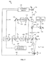
- Fig. 3 illustrates a preferred implementation of a cavity ring-down system 100 for optical heterodyne detection according to the general principles explained above.
- System 100 has a high finesse ring-down cavity 102 set up between three mirrors 104 , 106 and 108 .
- Cavity 102 may be located within an enclosure if designed for measuring the absorption of gases, and it need not have an enclosure if designed for measuring non-volatile samples, e.g., thin films.
- Mirror 104 is a plano-plano mirror serving as an input coupler and mirror 108 is a plano-plano mirror serving as an output coupler.
- Mirror 106 is a concave mirror.
- Ring-down cavity 110 has a ring resonator geometry, which is the most preferred type of cavity for practicing CRDS.
- a pump laser 110 which is preferably a high-quality, narrow linewidth laser tunable over a wavelength range of interest provides a light beam 112 .
- pump laser 110 generates a pump beam 112 whose wavelength range is selected to include the absorption peak(s) of interest of an absorptive sample 114 placed in ring-down cavity 102 .
- laser 110 is a Nd:YAG laser having an output power of 300 mW and a tunable range from 1064.44 nm to 1064.58 nm. This wavelength range permits one to study an absorption spectrum of a CO 2 transition at 1064 nm. Of course, this is an exemplary range used for demonstration purposes.
- a half-wave plate 116 followed by a polarizing beam splitter (PBS) 118 are placed in the path of beam 112 .
- Beam 112 contains an s-polarization E S and a p-polarization E P with respect to ring-down cavity 102 .
- Polarizations E S and E P are orthogonal to each other and their relative intensities can be adjusted with the aid of half-wave plate 116 .
- Polarization E S of beam 112 is used as a signal wave E SIGNAL
- polarization E P serves the function of a local oscillator wave E LO .
- PBS 118 separates polarization E S from polarization E P .
- Polarization E P is passed to a phase modulator (PM) 120 while polarization E S , after reflection from a mirror 122 , is passed to an acousto-optic modulator (AOM) 124 .
- AOM 124 has two functions. First, it frequency shifts polarization E S as necessary to allow both polarizations E P and E S to be simultaneously resonant in ring-down cavity 102 . In other words, AOM controls a frequency difference ⁇ between polarizations E P and E S ; difference ⁇ should be equal to the free spectral range of cavity 102 . Second, AOM 124 is also used to switch polarization E S on and off, i.e., AOM 124 is used to terminate polarization E S at required times to initiate the ring-down phase of cavity 102 .
- PM 120 is used to generate feedback from ring-down cavity 102 to allow one to lock laser 110 to cavity 102 . This can be performed in accordance to the Drever technique described by R. Drever et al. in Applied Physics B , 1983, B31, pg. 1997.
- Both polarizations E S and E P pass through mode-matching optics 126 , 128 generally indicated by lenses, and are recombined as beam 112 by a PBS 130 after polarization E S is reflected by a mirror 132 .
- Mode-matching optics 126 , 128 ensure modal purity of recombined beam 112 .
- recombined beam 122 is in the TEM 00 mode thus eliminating mode-beating and the associated optical noise sources.
- Beam 112 is injected into ring-down cavity 102 through input coupler 104 .
- E S polarization is used for absorption measurement and E P polarization is used for locking laser 110 to cavity 102 and as local oscillator wave E LO. Since cavity 102 is a ring resonator E P and E S polarizations reflected by cavity 102 do not retrace the path of original beam 112 . Hence, well-known feedback problems associated with portions of pump beam 112 being reflected back to laser 110 are avoided. Instead, E P and E S polarizations reflected from cavity 102 pass through input coupler 104 at an angle to beam 112 and E P polarization is isolated from E S polarization by a PBS 134 .
- Reflected E P polarization is detected by a photodetector or photodiode 136 and converted into an adjustment signal.
- the adjustment signal from photodiode 136 may be amplified by an amplifier (not shown) as necessary and delivered to a locking servo 138 .
- Locking servo 138 uses the adjustment signal to lock laser 110 to cavity 102 .
- servo 138 sends a high frequency portion of the adjustment signal via connection 140 to a first actuator 142 , e.g. a piezoelectric actuator (PZT).
- PZT 142 moves mirror 106 as indicated by arrow A and thereby adjusts the length of cavity 102 .
- This adjustment is performed for high frequency disturbances, e.g., in the kHz range.
- the unity gain frequency i.e., the center frequency for high frequency adjustments was set at 60 kHz.
- Low frequency adjustment signals are divided into very low and low frequency; the first having unity gain at 1 Hz and the second having unity gain at 100 Hz.
- the very low frequency adjustment signals are delivered via connection 144 to the temperature control (not shown) of laser 110 .
- the temperature control adjusts the temperature of laser 110 and thus adjusts the wavelength of beam 112 .
- the low frequency adjustment signals are sent to PZT 142 via connection 140 to adjust the length of cavity 102 .
- this method of locking laser 110 to cavity 102 may be modified in many ways. Also, other locking techniques known in the art may be utilized. However, it is important that laser 110 be locked to cavity 102 with sufficient accuracy ensure a high and stable optical throughput of light through cavity 102 . In other words, the locking should overcome the problem of intensity fluctuations produced during coupling between laser 110 and cavity 102 , thus eliminating coupling-related noise described in the background section. Furthermore, the locking should be stable for a sufficiently long period of time, i.e., for a period of at least one scan of sample 114 .
- a scanning unit 146 is connected to laser 110 for the purpose of tuning the wavelength of beam 112 over the tunable range.
- varying the length of cavity 102 with the aid of PZT 142 can also be employed for altering the resonant wavelength within cavity 102 and thus achieving some wavelength tuning or scanning.
- high speed scans e.g., in the ranges of hundreds of MHz/s
- a person of average skill in the art will recognize and implement the most viable scanning method in a given situation.
- AOM 124 is switched to interrupt the passage of E S polarization.
- E S polarization built-up inside cavity 102 rings down.
- a ring-down beam 148 containing both E S and E P polarizations corresponding to a ring-down wave E RD and local oscillator wave E LO issues from cavity 110 during the ring-down phase.
- a birefringent plate 150 and a PBS 154 positioned in the path of ring-down beam 148 serve as an optical combiner.
- the function of the optical combiner is to rotate polarizations E S and E P , or waves E RD and E LO in order to produce a projection whose amplitude is proportional to the product of E S and E P , or E RD and E LO .
- plate 150 rotates polarizations E S and E P , or waves E RD and E LO , by 45 °.
- a mirror 152 reflects the rotated waves E RD and E LO to PBS 154 which reflects 50% of each wave to a photodetector 156 . In this manner waves E RD and E LO are overlapped in an interference signal 158 .
- PM 120 as well as AOM 124 may be tuned to achieve precise overlap of the wave fronts of E RD and E LO waves.
- PM 120 serves to eliminate phase difference ⁇ between waves E RD and E LO .
- ACM 124 is used to fine tune frequency difference ⁇ . The optimal settings of all elements can be determined by monitoring a heterodyne current I H generated by photodetector 156 .
- a heterodyne detection circuit 160 receives heterodyne current I H and determines from it the second decay rate 1/2 ⁇ , as described above.
- a transimpedance amplifier (not shown) is used to amplify I H generated by photodetector 156 before delivering it to detection circuit 160 .
- Photodetector 156 captures interference signal 158 which contains only half of all light resulting from overlapping E RD and E LO . The other half is transmitted through PBS 154 in the form of a second interference signal 162 . As indicated in dashed lines, a second photodetector 164 can be provided to capture second interference signal 162 and generate a second heterodyne current I H . The two heterodyne currents can be added together in heterodyne detection circuit 160 to obtain a twice larger current signal. This type of dual-detector heterodyne detection technique (using photodetectors 156 and 164 ) produces a stronger heterodyne current I H , but is prone to additional noise. A person skilled in the art will recognize that careful balancing should be ensured when operating system 100 in the dual-detector mode.
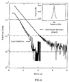
- Fig. 6 compares the graphs for 256 ring-down decays for direct or homodyne detection and heterodyne detection.
- the time scale for the heterodyne detection graph is halved to equalize decay times.
- the inset shows signal power levels for heterodyne detection.
- System 100 achieves an SNR increase of up to 31 dB over direct detection. A person of average skill in the art will recognize that further improvements in the electronics will allow system 100 to reach true shot-noise-limited sensitivity.
- the sensitivity and precision with which the absorption coefficients of sample 114 can be measured will depend only on the length of cavity 102 , reflectivity of mirrors 104 , 106 and 108 and laser noise statistics of laser 110 .
- Fig. 7 shows the spectrum of water vapor obtained in room air in comparison to accepted data published in HITRAN96.
- the sensitivity of system 100 to water vapor at atmospheric pressure is about 1 part per million.
- system 100 is easy to implement and permits the use of other noise reducing measures.
- system 100 takes advantage of laser to cavity locking and mode shaping. This makes system 100 attractive for practical CRDS implementations.
- Fig. 4 shows an alternative cavity ring-down system 200 .
- system 200 is supplied by light beam 112 from laser 110 .
- Beam 112 is split into E S and E P polarizations serving as signal wave E SIGNAL and local oscillator wave E LO by a splitter 170 .
- AOM 130 and a birefringent plate 172 are used to adjust signal frequency ⁇ SIGNAL and E S polarization.
- E P and E S polarizations are recombined in beam 112 by PBS 136 .
- Beam 112 is injected into cavity 102 .
- Reflected E P polarization is used for locking laser 110 to cavity 102 , as in the preferred embodiment, with the aid of PBS 134 , photodetector 136 and locking servo 138 .
- AOM 130 is used to interrupt E S polarization or signal wave E SIGNAL to start the ring-down phase of cavity 102 .
- Ring-down beam 148 issuing from cavity 102 during the ring-down phase contains orthogonal polarizations E P and E S .
- System 200 employs a single PBS 174 oriented at about 45° as a combiner for overlapping polarizations E P and E S to create interference signal 158 .
- 50% of the total light of ring-down beam 148 is contained in interference signal 158 sent to photodetector 156 .
- the remaining light is reflected by PBS 174 in second interference signal 162 which may or may not be used for heterodyne detection (not used in the embodiment shown).
- FIG. 5 Another alternative cavity ring-down system 300 is illustrated in Fig. 5.
- System 300 is analogous to preferred system 100 , with the exception that polarizations E P and E S reflected rather than transmitted by cavity 102 are used as ring-down beam 148 .
- the ring-down phase is preferably initiated by AOM 124 through shifting signal frequency ⁇ SIGNAL of polarization E S acting as signal wave E SIGNAL to a value at which wave E S is no longer resonant in cavity 102 .
- a birefringent plate 184 and PBS 180 act as a combiner to overlap polarizations E S and E P of ring-down beam 148 in interference signal 158 .
- a second interference signal 182 is transmitted by PBS 180 . Since only polarization E P is used by locking servo 138 , a filter 186 is placed in the path of interference signal 182 to filter out polarization E S based on its frequency. Thus, photodetector 136 receives polarization E P only and uses it for locking laser 110 to cavity 102 as in the previous embodiments.
- any of the frequency locked systems described above can be used for determination of the ring-up rate by the heterodyne technique. Because of intensity fluctuations during ring-up, laser to cavity locking or any other means of ensuring smooth light build-up in the ring-down cavity is required. The beginning of the measurement can coincide with the time when the AOM turns signal wave E SIGNAL on, e.g., after a ring-down has occurred.
- the waves generating the interference signal will be a ring-up wave E RU and the local oscillator wave E LO .
- ring-up wave E RU will exhibit a growth race 1/ ⁇ rather than a decay rate.
- the photodetector for receiving the interference signal is placed at a point of maximum overlap between the local oscillator wave E LO and the ring-up wave E RU .
- the photodetector generates a heterodyne current I H corresponding to the heterodyne component of the interference signal.
- the heterodyne current I H has a second growth rate 1/2 ⁇ . Otherwise, the heterodyne detection technique is applied in the same manner as during ring-down.
- the ring-down wave and local oscillator wave may have orthogonal but non-linear polarizations; e.g., they can have right-handed and left-handed circular polarizations.
- the optics for overlapping ring-down wave with local oscillator wave may include other polarization rotating elements besides birefringent plates and polarizing beam splitters.
- Faraday rotators and half wave plates may be used for this purpose in alternative embodiments. Additional optics may be employed such as walk-off elements required for spatially separating the orthogonal polarizations before being rotated in. Faraday rotators are well known in the art.
Landscapes
- Physics & Mathematics (AREA)
- Spectroscopy & Molecular Physics (AREA)
- General Physics & Mathematics (AREA)
- Optics & Photonics (AREA)
- Health & Medical Sciences (AREA)
- Life Sciences & Earth Sciences (AREA)
- Chemical & Material Sciences (AREA)
- Analytical Chemistry (AREA)
- Biochemistry (AREA)
- General Health & Medical Sciences (AREA)
- Immunology (AREA)
- Pathology (AREA)
- Investigating Or Analysing Materials By Optical Means (AREA)
- Lasers (AREA)
- Spectrometry And Color Measurement (AREA)
- Optical Measuring Cells (AREA)
Applications Claiming Priority (2)
| Application Number | Priority Date | Filing Date | Title |
|---|---|---|---|
| US295213 | 1999-04-21 | ||
| US09/295,213 US6094267A (en) | 1999-04-21 | 1999-04-21 | Optical heterodyne detection for cavity ring-down spectroscopy |
Publications (2)
| Publication Number | Publication Date |
|---|---|
| EP1046900A2 true EP1046900A2 (fr) | 2000-10-25 |
| EP1046900A3 EP1046900A3 (fr) | 2001-05-02 |
Family
ID=23136736
Family Applications (1)
| Application Number | Title | Priority Date | Filing Date |
|---|---|---|---|
| EP00300293A Withdrawn EP1046900A3 (fr) | 1999-04-21 | 2000-01-17 | Détection optique hétérodyne pour spectroscopie par abaisement de cavité d' anneau |
Country Status (5)
| Country | Link |
|---|---|
| US (1) | US6094267A (fr) |
| EP (1) | EP1046900A3 (fr) |
| JP (1) | JP2000338037A (fr) |
| AU (1) | AU1806600A (fr) |
| WO (1) | WO2000065300A1 (fr) |
Cited By (2)
| Publication number | Priority date | Publication date | Assignee | Title |
|---|---|---|---|---|
| EP1307714A4 (fr) * | 2000-07-12 | 2007-04-04 | Macquarie Res Ltd | Detection optique heterodyne en spectroscopie optique de ringdown de cavite |
| WO2013110023A1 (fr) * | 2012-01-20 | 2013-07-25 | Purdue Research Foundation | Procédé et dispositif d'imagerie optique avec un ensemble amplificateur résonnant |
Families Citing this family (35)
| Publication number | Priority date | Publication date | Assignee | Title |
|---|---|---|---|---|
| US6727492B1 (en) * | 2000-01-13 | 2004-04-27 | Regents Of The University Of Colorado | Cavity ringdown spectroscopy system using differential heterodyne detection |
| US6377350B1 (en) * | 2000-02-03 | 2002-04-23 | Informal Diagnostics, Inc | Frequency sequencing using CRDS |
| US6532072B1 (en) * | 2000-03-13 | 2003-03-11 | The United States Of America As Represented By The Secretary Of The Air Force | Fiber-amplifier cavity for cavity ring down spectroscopy |
| US6768548B2 (en) * | 2001-02-01 | 2004-07-27 | The Board Of Trustees Of The Leland Stanford Junior University | Pulse-by-pulse cavity ring-down spectroscopy |
| US6865198B2 (en) | 2002-09-27 | 2005-03-08 | Battelle Memorial Institute | Cavity ringdown spectroscopy system and method |
| DE10255022A1 (de) * | 2002-11-25 | 2004-06-17 | Fiedler, Sven E. | Resonatorverstärktes Absorptions-Spektrometer |
| US7230712B2 (en) * | 2003-11-03 | 2007-06-12 | Battelle Memorial Institute | Reduction of residual amplitude modulation in frequency-modulated signals |
| US20050254056A1 (en) * | 2004-05-13 | 2005-11-17 | Alexander Kachanov | System and method for controlling the light source of a cavity ringdown spectrometer |
| JP4486433B2 (ja) * | 2004-07-29 | 2010-06-23 | 浜松ホトニクス株式会社 | 吸収計測装置 |
| US7193765B2 (en) * | 2005-03-31 | 2007-03-20 | Evans & Sutherland Computer Corporation | Reduction of speckle and interference patterns for laser projectors |
| US7855788B2 (en) | 2005-09-07 | 2010-12-21 | Nu Eco Engineering Co., Ltd. | Spectroscopy method and spectroscope |
| US7541586B2 (en) | 2006-11-10 | 2009-06-02 | The George Washington University | Compact near-IR and mid-IR cavity ring down spectroscopy device |
| US7569823B2 (en) | 2006-11-10 | 2009-08-04 | The George Washington University | Compact near-IR and mid-IR cavity ring down spectroscopy device |
| US8405827B2 (en) * | 2006-11-21 | 2013-03-26 | Ricardo Claps | Time-resolved spectroscopy system and methods for multiple-species analysis in fluorescence and cavity-ringdown applications |
| CN101617354A (zh) | 2006-12-12 | 2009-12-30 | 埃文斯和萨瑟兰计算机公司 | 用于校准单个调制器投影仪中的rgb光的系统和方法 |
| US7612885B2 (en) * | 2006-12-22 | 2009-11-03 | Honeywell International Inc | Spectroscopy method and apparatus for detecting low concentration gases |
| US8358317B2 (en) | 2008-05-23 | 2013-01-22 | Evans & Sutherland Computer Corporation | System and method for displaying a planar image on a curved surface |
| US8702248B1 (en) | 2008-06-11 | 2014-04-22 | Evans & Sutherland Computer Corporation | Projection method for reducing interpixel gaps on a viewing surface |
| US8040518B2 (en) | 2008-10-07 | 2011-10-18 | Entanglement Technologies, Inc. | Cavity enhanced trace gas detection gradiometer |
| US8198590B2 (en) * | 2008-10-30 | 2012-06-12 | Honeywell International Inc. | High reflectance terahertz mirror and related method |
| US7864326B2 (en) | 2008-10-30 | 2011-01-04 | Honeywell International Inc. | Compact gas sensor using high reflectance terahertz mirror and related system and method |
| US8077378B1 (en) | 2008-11-12 | 2011-12-13 | Evans & Sutherland Computer Corporation | Calibration system and method for light modulation device |
| JP2011163767A (ja) * | 2010-02-04 | 2011-08-25 | Kinki Univ | キャビティリングダウン分光装置、吸光分析装置及びキャビティリングダウン分光方法 |
| US9641826B1 (en) | 2011-10-06 | 2017-05-02 | Evans & Sutherland Computer Corporation | System and method for displaying distant 3-D stereo on a dome surface |
| CN104406931B (zh) * | 2014-12-16 | 2017-06-30 | 中国人民解放军国防科学技术大学 | 碱金属激光器增益介质原子浓度和温度检测装置及方法 |
| DE102015009595A1 (de) * | 2015-07-24 | 2017-01-26 | Universität Heidelberg | Verfahren und Vorrichtung zur Kalibration eines optischen Resonators, Verwendung der Vorrichtung, Verwendung eines optischen Modulators und Computerprogrammprodukt |
| US10527492B2 (en) | 2017-05-16 | 2020-01-07 | Li-Cor, Inc. | Mode matching method for absorption spectroscopy systems |
| CN109142244B (zh) * | 2018-06-22 | 2024-07-02 | 山东建筑大学 | 一种多衰荡干涉型全光纤气体传感器 |
| CN109489939B (zh) * | 2018-11-15 | 2020-09-25 | 中国科学院光电技术研究所 | 一种高反光学元件的s、p偏振反射率及相位差高精度同时测量方法 |
| US11209314B2 (en) | 2019-12-20 | 2021-12-28 | Government Of The United States Of America, As Represented By The Secretary Of Commerce | Cavity buildup dispersion spectrometer and performing cavity buildup dispersion spectroscopy |
| US11946857B2 (en) * | 2020-08-04 | 2024-04-02 | Picomole Inc. | System and method for frequency matching a resonance cavity to a light source |
| CN114018868B (zh) * | 2021-10-27 | 2023-07-18 | 山西大学 | 一种基于光学反馈的线性腔衰荡光谱装置及方法 |
| CN114720402A (zh) * | 2022-03-31 | 2022-07-08 | 中国科学院光电技术研究所 | 一种复合传感无源腔标定装置 |
| US11913835B1 (en) * | 2023-07-17 | 2024-02-27 | Vector Atomic, Inc. | Vector noise subtraction in vapor cell spectroscopy |
| US20250385735A1 (en) * | 2024-06-14 | 2025-12-18 | Marco MENCHETTI | Systems for the Transfer of Stability from an Optical to a RF Source |
Family Cites Families (5)
| Publication number | Priority date | Publication date | Assignee | Title |
|---|---|---|---|---|
| US4193690A (en) * | 1977-10-19 | 1980-03-18 | University Of Southern California | Heterodyne detection of coherent Raman signals |
| US4905244A (en) * | 1986-09-26 | 1990-02-27 | United States Department Of Energy | Heterodyne laser spectroscopy system |
| US4817101A (en) * | 1986-09-26 | 1989-03-28 | The United States Of America As Represented By The United States Department Of Energy | Heterodyne laser spectroscopy system |
| US5528040A (en) * | 1994-11-07 | 1996-06-18 | Trustees Of Princeton University | Ring-down cavity spectroscopy cell using continuous wave excitation for trace species detection |
| US6084682A (en) * | 1998-04-15 | 2000-07-04 | The Board Of Trustees Of The Leland Stanford Junior University | Cavity-locked ring down spectroscopy |
-
1999
- 1999-04-21 US US09/295,213 patent/US6094267A/en not_active Expired - Lifetime
- 1999-07-20 WO PCT/US1999/012391 patent/WO2000065300A1/fr not_active Ceased
- 1999-07-20 AU AU18066/00A patent/AU1806600A/en not_active Abandoned
-
2000
- 2000-01-17 EP EP00300293A patent/EP1046900A3/fr not_active Withdrawn
- 2000-04-21 JP JP2000121831A patent/JP2000338037A/ja active Pending
Cited By (3)
| Publication number | Priority date | Publication date | Assignee | Title |
|---|---|---|---|---|
| EP1307714A4 (fr) * | 2000-07-12 | 2007-04-04 | Macquarie Res Ltd | Detection optique heterodyne en spectroscopie optique de ringdown de cavite |
| WO2013110023A1 (fr) * | 2012-01-20 | 2013-07-25 | Purdue Research Foundation | Procédé et dispositif d'imagerie optique avec un ensemble amplificateur résonnant |
| US9222878B2 (en) | 2012-01-20 | 2015-12-29 | Purdue Research Foundation | Method and device for optical imaging with a resonant amplifier assembly |
Also Published As
| Publication number | Publication date |
|---|---|
| AU1806600A (en) | 2000-11-10 |
| US6094267A (en) | 2000-07-25 |
| JP2000338037A (ja) | 2000-12-08 |
| WO2000065300A1 (fr) | 2000-11-02 |
| EP1046900A3 (fr) | 2001-05-02 |
Similar Documents
| Publication | Publication Date | Title |
|---|---|---|
| US6094267A (en) | Optical heterodyne detection for cavity ring-down spectroscopy | |
| US6233052B1 (en) | Analog detection for cavity lifetime spectroscopy | |
| US9711932B2 (en) | Optical signal processing with modelocked lasers | |
| US6084682A (en) | Cavity-locked ring down spectroscopy | |
| US6466322B1 (en) | Swept continuous wave cavity ring-down spectroscopy | |
| Paldus et al. | Cavity-locked ring-down spectroscopy | |
| US6727492B1 (en) | Cavity ringdown spectroscopy system using differential heterodyne detection | |
| US4902125A (en) | Optical system having beam amplification | |
| CN112098737A (zh) | 一种微波电场强度的测量方法及装置 | |
| US8537362B2 (en) | Cavity ring down spectroscopy using measured backward mode data | |
| Bigelow et al. | Accurate optical measurement of nuclear polarization in optically pumped 3He gas | |
| CN118483178B (zh) | 一种获得脉冲里德堡原子光谱的装置和方法 | |
| CN109580541A (zh) | 一种光学外差法腔衰荡光谱测量装置及方法 | |
| Levenson et al. | Optical heterodyne detection in cavity ring-down spectroscopy | |
| Marino et al. | Classical signature of ponderomotive squeezing in a suspended mirror resonator | |
| US12586977B2 (en) | Method and apparatus for measuring a time delay between pairs of pulses from laser pulse sequences, and applications thereof | |
| Bethune et al. | Laser IR polarization spectroscopy at surfaces | |
| Swofford et al. | New two− photon absorption spectrometer and its application to diphenylbutadiene | |
| Scalabrin et al. | Optically pumped cw CH2DOH FIR laser: New lines and frequency measurements | |
| EP4375643B1 (fr) | Appareil de détection quantitative d'isotopologue de dioxyde de carbone utilisant un spectromètre et un absorption à deux photons | |
| JPH0766257A (ja) | 和周波測定装置 | |
| RU2408909C2 (ru) | Способ регистрации отраженного лазерного излучения и устройство для регистрации отраженного лазерного излучения | |
| RU1805351C (ru) | Способ измерени параметров светонаведенных дихроизма и двулучепреломлени | |
| CN119534334B (zh) | 一种快速扫描腔衰荡光谱实现系统及应用 | |
| JPH06273386A (ja) | 超音波の検出装置 |
Legal Events
| Date | Code | Title | Description |
|---|---|---|---|
| PUAI | Public reference made under article 153(3) epc to a published international application that has entered the european phase |
Free format text: ORIGINAL CODE: 0009012 |
|
| AK | Designated contracting states |
Kind code of ref document: A2 Designated state(s): AT BE CH CY DE DK ES FI FR GB GR IE IT LI LU MC NL PT SE |
|
| AX | Request for extension of the european patent |
Free format text: AL;LT;LV;MK;RO;SI |
|
| PUAL | Search report despatched |
Free format text: ORIGINAL CODE: 0009013 |
|
| AK | Designated contracting states |
Kind code of ref document: A3 Designated state(s): AT BE CH CY DE DK ES FI FR GB GR IE IT LI LU MC NL PT SE |
|
| AX | Request for extension of the european patent |
Free format text: AL;LT;LV;MK;RO;SI |
|
| AKX | Designation fees paid | ||
| REG | Reference to a national code |
Ref country code: DE Ref legal event code: 8566 |
|
| STAA | Information on the status of an ep patent application or granted ep patent |
Free format text: STATUS: THE APPLICATION IS DEEMED TO BE WITHDRAWN |
|
| 18D | Application deemed to be withdrawn |
Effective date: 20011103 |