EP1047036A1 - Vielachsiger Universalständer für Preishalter, Werbekartenhalter und/oder Anzeiger - Google Patents
Vielachsiger Universalständer für Preishalter, Werbekartenhalter und/oder Anzeiger Download PDFInfo
- Publication number
- EP1047036A1 EP1047036A1 EP19990830232 EP99830232A EP1047036A1 EP 1047036 A1 EP1047036 A1 EP 1047036A1 EP 19990830232 EP19990830232 EP 19990830232 EP 99830232 A EP99830232 A EP 99830232A EP 1047036 A1 EP1047036 A1 EP 1047036A1
- Authority
- EP
- European Patent Office
- Prior art keywords
- arm
- base
- bracket
- peg
- turnable
- Prior art date
- Legal status (The legal status is an assumption and is not a legal conclusion. Google has not performed a legal analysis and makes no representation as to the accuracy of the status listed.)
- Withdrawn
Links
- 230000001737 promoting effect Effects 0.000 title description 8
- 238000007373 indentation Methods 0.000 claims abstract description 7
- 230000008878 coupling Effects 0.000 claims description 14
- 238000010168 coupling process Methods 0.000 claims description 14
- 238000005859 coupling reaction Methods 0.000 claims description 14
- 230000000007 visual effect Effects 0.000 claims description 10
- 238000000465 moulding Methods 0.000 claims description 5
- 229920001971 elastomer Polymers 0.000 claims description 4
- 239000000806 elastomer Substances 0.000 claims description 4
- 229920005176 Hostaform® Polymers 0.000 description 1
- 229920000122 acrylonitrile butadiene styrene Polymers 0.000 description 1
- 230000000903 blocking effect Effects 0.000 description 1
- 239000000463 material Substances 0.000 description 1
- 239000002184 metal Substances 0.000 description 1
- 229920001778 nylon Polymers 0.000 description 1
- 239000004033 plastic Substances 0.000 description 1
- 229920005989 resin Polymers 0.000 description 1
- 239000011347 resin Substances 0.000 description 1
Images


Classifications
-
- G—PHYSICS
- G09—EDUCATION; CRYPTOGRAPHY; DISPLAY; ADVERTISING; SEALS
- G09F—DISPLAYING; ADVERTISING; SIGNS; LABELS OR NAME-PLATES; SEALS
- G09F7/00—Signs, name or number plates, letters, numerals, or symbols; Panels or boards
- G09F7/18—Means for attaching signs, plates, panels, or boards to a supporting structure
- G09F7/22—Means for attaching signs, plates, panels, or boards to a supporting structure for rotatably or swingably mounting, e.g. for boards adapted to be rotated by the wind
Definitions
- the present invention relates to implements and devices for visual communications installed along display shelves of shops and supermarket.
- it relates to a multipurpose stand for price tag holders, promotional cards and similar visual communication implements.
- shop shelves on which the goods are placed have a frontal molding onto which clip-cursors may be easily installed and forcibly slid along the molding.
- clip-cursors On special couplings means present on the clip-cursor promotional cards and price holders provided with cooperating couplings means may be installed.
- a multipurpose supporting device that is, a device that may be installed on whatsoever structure, being this a front molding, the edge of a shelf or a post, a tubular or metal wire structure, a box or container, and be orientable in any desired spatial position to support standard or flag-like price holders, promotional cards, and the like.
- the universal support for price-holders, promotional cards, indicators and similar visual communication implements comprises a fixing clip in the form of a peg with jaws coated or equipped with grooved inserts of elastomer, capable to grip onto structural elements of any shape.
- the end of one of the two arms of the peg is bent toward the other arm forming an orthogonal base-plate.
- a "plinth” is pivotally mounted onto such a base-plate, such to be able to be rotate about a first axis normal to the plane of the base-plate termination of the peg's arm, by forcing the surmounting of cooperating ridges and depressions functionally formed on juxtaposed assembling surfaces of the turning plinth and of the base-plate termination of the peg's arm.
- a slender post or orientable arm of the "universal" support of the invention has one end pivotally mounted on the plinth such to be able to be rotated about a second axis, orthogonal to the first axis, again by forcing the surmounting of cooperating ridges and depressions functionally formed on juxtaposed assembling surfaces of the orientable arm's and of the plinth pivotally mounted of the base-plate termination of the peg's arm.
- the free end of the orientable arm may ends with a shank having a generally polygonal section.
- the shank fits in a non-turning manner into a cooperating female receptacle of a price holder or a promotional card frame or of a flag-like projecting promotional card or of any similar visual communication implement.
- the universal multipivot support of the invention offers an outstanding freedom to spatially orient the supported implement to ensure an optimal visibility regardless of the fixing possibilities offered by the structure.
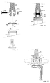
- the fastening element of the universal multiple joint support of the invention is constituted by a peg, indicated as a whole with 2.
- the peg's jaws 3 and 4 are constituted by grooved inserts of elastomer and ensure a firm grip to differently shaped structure members.
- the peg 2 has a U-shaped flat spring, although other types of spring may be alternatively utilized, such as for example a helical spring.
- One of two arms of the peg (6 in the example shown) has its end bent toward the opposite arm 7, forming a base-plate or bracket 8, substantially orthogonal to the peg's arm 6.
- bracket 8 On this bracket 8 is installed a turnable base or plinth 9, held by a counter washer 10 which is compressed against the top surface of the bracket 8.
- the end of one orientable arm 11 is pivotally mounted on the turning base or plinth 9, by means of an assembling bolt 12.
- the orientable arm 11 has an shank 16 with a polygonal cross section point 16a, suitable to fit into a cooperating receptacle 13a of a socket 13 of an adapter 14 to hold a price holder or a flag-like card holder or of another adapter 15 ( Figure 3), for example for message frames or other types of price holders and alike.
- FIG. 4 shows the main components of the fastening peg 2 of the universal multiple-joint support, to fasten it to any vertical, slanted or horizontal member, of a fixed structure and of the turnable base or plinth 9 mounted on the bracket termination of the peg's arm 6.
- the turnable base 9 has a terminal circular flange 9a fitting into a circular stepped hole 9h present in the bracket 8.
- the counter washer 10 has a central slot 9g through which the vertical bracket 9d pass. On the bottom face of counter washer 10 there are radial ridges 9b and the counter washer 10 has a convex top face.
- Figures 5 and 6 respectively exploded and assembled detail views, show how the turnable base 9 is introduced in the hole 9h of the bracket termination 8 of the peg's arm 6, the counter washer 10 is inserted as a counter flange along the vertical bracket 9d of the turnable base and the fork-like termination 11a of the orientable arm 11 is inserted, and the assembly is ultimately held by the pivot bolt 12 blocked by the nut 12a.
- the two arms of the fork-like termination 11a of the orientable arm 11 end with a circular perimeter and once the assembly is complete, they bear on the tangent surface of the top convex face of the counter washer 10.
- the partial side view of figure 7 shows how spaced indentations 9e present along the circular perimeter of the vertical bracket 9d cooperate with the probing fingers 11 b formed at the notch of the fork end 11 a of the arm 11, in defining as several preordered angular positions.
- spaced indentations 9e present along the circular perimeter of the vertical bracket 9d cooperate with the probing fingers 11 b formed at the notch of the fork end 11 a of the arm 11, in defining as several preordered angular positions.
- more closely spaced indentations along the perimeter of the vertical bracket 9d will provide for more selectable angular of the swingable arm 11.
- Orientation of the turnable base 9 is also preorderly established by forcing the surmounting by the radial ridges 9b present on the coupling face of the counter washer 10 of the flat portions of surface that separate a coordinated plurality of radial depressions present on the coupling face of the bracket 8 (not shown in the figures), such to determine an orientability of the turnable base 9 through relatively small pre-established angular increments along the whole circumference.
- the shank 16 of the free end of the orientable arm 11 fitting in the cooperating receptacle of any suitable type of adapter 14, 15 prevent any undesired rotation of the adapter about the arm's axis.
- all the pieces that compose the universal multiple joint support of the invention may be fabricated by molding, employing a suitable plastic material, such as for example ABS, Nylon®, Hostaform® and alike resins.
- the pivot coupling between the swingable arm 11 and the turnable base 9 may be realized in a different manner that that of the figures.
- the coupling between the end of the arm 11 and the base 9 may employ radial ridges and cooperating radial grooves respectively made on juxaposed coupling faces between the vertical bracket 9d and the arm's end, rather than between the indentations 9e and the fingers 11b.
Landscapes
- Physics & Mathematics (AREA)
- General Physics & Mathematics (AREA)
- Engineering & Computer Science (AREA)
- Theoretical Computer Science (AREA)
- Pivots And Pivotal Connections (AREA)
Priority Applications (1)
| Application Number | Priority Date | Filing Date | Title |
|---|---|---|---|
| EP19990830232 EP1047036A1 (de) | 1999-04-21 | 1999-04-21 | Vielachsiger Universalständer für Preishalter, Werbekartenhalter und/oder Anzeiger |
Applications Claiming Priority (1)
| Application Number | Priority Date | Filing Date | Title |
|---|---|---|---|
| EP19990830232 EP1047036A1 (de) | 1999-04-21 | 1999-04-21 | Vielachsiger Universalständer für Preishalter, Werbekartenhalter und/oder Anzeiger |
Publications (1)
| Publication Number | Publication Date |
|---|---|
| EP1047036A1 true EP1047036A1 (de) | 2000-10-25 |
Family
ID=8243365
Family Applications (1)
| Application Number | Title | Priority Date | Filing Date |
|---|---|---|---|
| EP19990830232 Withdrawn EP1047036A1 (de) | 1999-04-21 | 1999-04-21 | Vielachsiger Universalständer für Preishalter, Werbekartenhalter und/oder Anzeiger |
Country Status (1)
| Country | Link |
|---|---|
| EP (1) | EP1047036A1 (de) |
Citations (5)
| Publication number | Priority date | Publication date | Assignee | Title |
|---|---|---|---|---|
| US3877163A (en) * | 1973-12-17 | 1975-04-15 | Claude Bissonet | Identification bracket |
| US4192441A (en) * | 1978-07-17 | 1980-03-11 | John Thomas Batts, Inc. | Clamp construction for article hangers |
| US4786025A (en) * | 1987-08-27 | 1988-11-22 | Eee Corporation | Anti-twist signholder support assembly |
| US4881707A (en) * | 1989-02-23 | 1989-11-21 | Clamp Swing Pricing Co. | Sign holder device |
| DE29622598U1 (de) * | 1996-12-30 | 1997-02-20 | Groß, Heidemarie, 13127 Berlin | Werbe- und Informationsträger, insbesondere Preisschildhalter |
-
1999
- 1999-04-21 EP EP19990830232 patent/EP1047036A1/de not_active Withdrawn
Patent Citations (5)
| Publication number | Priority date | Publication date | Assignee | Title |
|---|---|---|---|---|
| US3877163A (en) * | 1973-12-17 | 1975-04-15 | Claude Bissonet | Identification bracket |
| US4192441A (en) * | 1978-07-17 | 1980-03-11 | John Thomas Batts, Inc. | Clamp construction for article hangers |
| US4786025A (en) * | 1987-08-27 | 1988-11-22 | Eee Corporation | Anti-twist signholder support assembly |
| US4881707A (en) * | 1989-02-23 | 1989-11-21 | Clamp Swing Pricing Co. | Sign holder device |
| DE29622598U1 (de) * | 1996-12-30 | 1997-02-20 | Groß, Heidemarie, 13127 Berlin | Werbe- und Informationsträger, insbesondere Preisschildhalter |
Similar Documents
| Publication | Publication Date | Title |
|---|---|---|
| US5816550A (en) | Shelf mounting arrangements for electronic shelf displays or similar articles | |
| US20030057336A1 (en) | Display hangar for providing anti-tip and locking features for use on pegboard, slat wall and the like | |
| US4319731A (en) | Merchandise display assembly | |
| US4826022A (en) | Display panel assembly | |
| US5231779A (en) | Information display tag | |
| US5136557A (en) | Modular watch collar | |
| US6644483B1 (en) | Hanger display assembly | |
| US6378818B1 (en) | Multi-position sign-mounting system | |
| US20040099618A1 (en) | Ambidextrous merchandise fixture and method of displaying merchandise therefrom | |
| JP2007532184A (ja) | ブリスターフックに電子棚ラベルを取り付けるアダプタ | |
| WO1991003967A1 (en) | Anti-pilferage system | |
| US4881707A (en) | Sign holder device | |
| US7584930B2 (en) | Anti-pilfer hook | |
| US6264148B1 (en) | Method and apparatus for displaying articles | |
| US6612057B2 (en) | Self centering display fixture | |
| US9476544B2 (en) | Universal display arm holder | |
| US2927701A (en) | Display hanger | |
| US6783011B2 (en) | Merchandise hanger | |
| KR101867245B1 (ko) | 가격태그용 홀더 | |
| US20030196974A1 (en) | Retail hanger display system | |
| US7641061B1 (en) | Retail hanger display system | |
| US6108956A (en) | Tri-mount sign system | |
| US6457689B1 (en) | Sign support having offset pivot | |
| US7334763B1 (en) | Socket hook bracket assembly | |
| US6412204B1 (en) | Self centering display fixture |
Legal Events
| Date | Code | Title | Description |
|---|---|---|---|
| PUAI | Public reference made under article 153(3) epc to a published international application that has entered the european phase |
Free format text: ORIGINAL CODE: 0009012 |
|
| AK | Designated contracting states |
Kind code of ref document: A1 Designated state(s): AT BE CH CY DE DK ES FI FR GB GR IE IT LI LU MC NL PT SE |
|
| AX | Request for extension of the european patent |
Free format text: AL;LT;LV;MK;RO;SI |
|
| STAA | Information on the status of an ep patent application or granted ep patent |
Free format text: STATUS: THE APPLICATION HAS BEEN WITHDRAWN |
|
| 18W | Application withdrawn |
Withdrawal date: 20010424 |