EP1047047A2 - Méthode et appareil de codage et décodage de signal audio et supports d'enregistrement avec des programmes à cette fin - Google Patents
Méthode et appareil de codage et décodage de signal audio et supports d'enregistrement avec des programmes à cette fin Download PDFInfo
- Publication number
- EP1047047A2 EP1047047A2 EP00105923A EP00105923A EP1047047A2 EP 1047047 A2 EP1047047 A2 EP 1047047A2 EP 00105923 A EP00105923 A EP 00105923A EP 00105923 A EP00105923 A EP 00105923A EP 1047047 A2 EP1047047 A2 EP 1047047A2
- Authority
- EP
- European Patent Office
- Prior art keywords
- coefficient
- segments
- frequency
- coefficient segments
- decoding
- Prior art date
- Legal status (The legal status is an assumption and is not a legal conclusion. Google has not performed a legal analysis and makes no representation as to the accuracy of the status listed.)
- Granted
Links
Images







Classifications
-
- G—PHYSICS
- G10—MUSICAL INSTRUMENTS; ACOUSTICS
- G10L—SPEECH ANALYSIS TECHNIQUES OR SPEECH SYNTHESIS; SPEECH RECOGNITION; SPEECH OR VOICE PROCESSING TECHNIQUES; SPEECH OR AUDIO CODING OR DECODING
- G10L19/00—Speech or audio signals analysis-synthesis techniques for redundancy reduction, e.g. in vocoders; Coding or decoding of speech or audio signals, using source filter models or psychoacoustic analysis
- G10L19/02—Speech or audio signals analysis-synthesis techniques for redundancy reduction, e.g. in vocoders; Coding or decoding of speech or audio signals, using source filter models or psychoacoustic analysis using spectral analysis, e.g. transform vocoders or subband vocoders
- G10L19/0212—Speech or audio signals analysis-synthesis techniques for redundancy reduction, e.g. in vocoders; Coding or decoding of speech or audio signals, using source filter models or psychoacoustic analysis using spectral analysis, e.g. transform vocoders or subband vocoders using orthogonal transformation
Definitions
- the present invention relates to methods and apparatus for encoding an audio signal into a digital code with high efficiency and for decoding the digital code into the audio signal, which can be employed for recording and reproduction of audio signals and their transmission and broadcasting over a communication channel.
- a conventional high-efficiency audio-coding scheme is such a transform coding method as depicted in Fig. 1.
- an audio signal input as a sequence of signal samples is transformed into frequency-domain coefficients in a time-frequency transformation part 11 upon each input of a fixed number of samples and then encoded and the encoded frequency-domain coefficients are preprocessed in a preprocessing part 2 and quantized in a quantization part 3.
- a typical example of this scheme is TWINVQ (Transform-domain Weighted Interleave Vector Quantization).
- the TWINVQ scheme uses weighted interleave vector quantization at the final stage of the quantization part 3.
- the vector quantization features two-stage flattening of coefficients in the preprocessing part 2 since the quantization efficiency increases as the distribution of input coefficient values becomes more even.
- the frequency-domain coefficients are normalized by the LPC spectrum to thereby roughly flatten their total variations.
- frequency-domain coefficients are further normalized for each of subbands having the same bandwidth on the Bark scale, by which they are flattened more finely than in the first stage.
- the Bark scale is a kind of frequency scale.
- the Bark scale has a feature that frequencies at equally spaced points provide pitches of sound nearly equally spaced apart in terms of the human auditory sense.
- the subbands of the same bandwidth on the Bark scale are approximately equal in width perceptually, but on a linear scale their bandwidth increases with an increase in frequency as shown in Fig. 2. Accordingly, when the frequency-domain coefficients are split into subbands having similar bandwidth on the Bark scale, the higher the frequency of the subband, the more it contains coefficients.
- the second-stage flattening on the Bark scale is intended to effectively allocate a limited amount of information, taking the human auditory sense into account.
- the flattening operation by normalization for each subband on the Bark scale is based on the expectation that the coefficients in the subbands are steady, but since the subbands at higher frequencies contain more coefficients, the situation occasionally arises where the coefficients are not steady in the subbands as depicted in Fig. 2. This incurs impairment of the efficiency of vector quantization, leading to the degradation of sound quality of decoded audio signals. Such a problem is likely to occur especially when the input audio signal contains a lot of tone components in the high-frequency range.
- TWINVQ Transformed Domain Interleave Vector Quantization
- the quantization may also be scalar quantization using adaptive bit allocation.
- Such a coding method splits the frequency-domain coefficients into subbands and conducts optimum bit allocation for each subband.
- the subbands may sometimes be divided so that they have the same bandwidth on the Bark scale with a view to achieving a better match to the human auditory sense. In this instance, however, the coefficients in the subbands at the higher frequencies are often unsteady as is the case with the TWINVQ scheme, leading to impairment of the quantization efficiency.
- Japanese Patent Application Laid-Open Gazette No. 7-248145 describes a scheme which separates pitch components formed by equally spaced tone components and encoding them individually.
- the position information of the pitch components is given by the fundamental frequency of the pitch, and hence the amount of information involved is small; however, in the case of a metallic sound or the like of a non-integral harmonic structure, the tone components cannot accurately be separated.
- an audio signal coding method for coding input audio signal samples comprising the steps of:
- a decoding method for decoding input digital codes into audio signal samples and outputting them comprising the steps of:
- a decoding method comprises the steps of:
- a coding apparatus which encodes input audio signal samples into output digital codes, the apparatus comprising:
- a coding apparatus which comprises:
- a decoding apparatus which decodes input digital codes into audio signal samples, the apparatus comprising:
- a decoding apparatus which comprises:
- the input signal is transformed into a contiguous sequence of frequency-domain coefficients, which is divided into coefficient segments for each band of about 100 Hz, and the coefficient segments are classified into at least two groups according to their intensity, for example, high- and low-level groups.
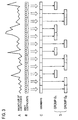
- the frequency-domain coefficients vary in magnitude as depicted in Fig. 3, Row A
- adjoining frequency-domain coefficients or coefficients of modified discrete cosine transform (MDCT) shown in Fig. 3 Row B are put together into coefficient segments as depicted in Fig. 3, Row C and these coefficient segments are classified into groups G 0 and G 1 according to their intensity as shown in Fig. 3, Row D.
- the high- and low-intensity groups G 0 and G 1 are processed independently of each other.
- One possible method for the independent processing after classification is to quantize the coefficients of the two groups G 0 and G 1 separately; an alternative is to vector quantize the coefficients of the two groups G 0 and G 1 after flattening them independently of each other.
- the coefficient segments belonging to each of the two groups after classification are based on the same sound source, the intensity variation in each group is small. Accordingly, it is possible to achieve highly efficient quantization while keeping perceptually good allocation of information over equal bandwidths, if the independent processing after classification is carried out for each of equally spaced sub-bands on the Bark scale.
- the coefficient segments may also be grouped into three or more.
- the coefficient segments are classified into plural groups, then flattened for each group and encoded, while at the same time classification information is encoded. Since this classification information is easy of compression as compared with the position information needed in the method set forth in the aforementioned Japanese Patent Application Laid-Open Gazette No. 7-168593, the amount of information involved can be suppressed; hence, the classification information can be encoded with high efficiency.
- Fig. 4 illustrates in block form a first embodiment of the present invention.
- Processing parts 11 through 18 constitute a coding part 10, which is supplied with an audio signal x as a sample sequence and outputs a coded bit sequence C.
- Processing parts 31 through 36 constitute a decoding part 30, which is supplied with the coded bit sequence C and outputs the audio signal x as a sample sequence.
- the input audio signal x is provided as a sample sequence to a time-frequency transformation part 11, which performs time-frequency transform upon each input of a fixed number N of samples to obtain N frequency-domain coefficients.
- This time-frequency transform can be done by discrete cosine transform (DCT) or modified discrete cosine transform (MDCT).
- DCT discrete cosine transform
- MDCT modified discrete cosine transform
- every N input audio samples and the immediately preceding N samples that is, a total of 2 ⁇ N audio samples, are transformed into N frequency-domain coefficients.
- the input samples may also be multiplied by a Hamming or Hanning window function immediately prior to the time-frequency transform processing.
- the magnitude M of the coefficient segment may be set to an arbitrary integral value equal to or greater than 1, but it is effective in increasing coding efficiency to set the magnitude M of the coefficient segment such that its frequency width becomes, for example, approximately 100 Hz. For instance, when the input signal sampling frequency is 48 kHz, the magnitude M of the coefficient segment is set to around 8. While the value M is described here to be common to all the coefficient segments, it may be set individually for each segment.
- the coefficient segments thus created in the coefficient segment generating part 12 are fed to a coefficient segment classification determining part 13 and a coefficient segment classifying part 14.
- Fig. 5 illustrates in block form a detailed configuration of the coefficient segment classification determining part 13.
- a sequence of coefficient-segmental intensity I is split by a band splitting part 3-2 into subbands.
- the thus split segmental intensity is expressed by I sb (i sb , q sb ), where i sb denotes the number of each subband and q sb the segment number in the subband.
- the number of coefficient segments in one subband is an arbitrary number equal to or greater than 2, which is given by Q sb (i sb ).
- the segmental intensity thus split into subbands by the band splitting part 3-2 is provided to a threshold determining part 3-3, segment classification decision part 3-4 and a degree-of-separation calculating part 3-5.
- T sb (i ab ) ⁇ I sb (i sb , q max ) + (1 - ⁇ )I sb (i sb , q min )
- q min is the number of the coefficient segment of the minimum value of the segmental intensity I sb
- q max is the number of the coefficient segment of the maximum value of the segmental intensity I sb
- ⁇ is a constant satisfying 1 ⁇ >0.
- the value of the constant ⁇ is set at about 0.4.
- the segment classification information G(q) thus determined is provided to the degree-of-separation calculating part 3-5 and a classification information output part 3-7.
- the calculation of the degree of separation is preceded by the calculation of the intensity values of the two groups.
- the degree of separation D sb (i sb ) thus determined for each subband i sb is provided to a segment classification use/nonuse determining part 3-6.
- the segment classification use/nonuse determining part 3-6 determines for each subband whether to use the segment classification.
- a segment classification use flag F sb (i sb ) is set at 1.
- the flag F sb (i sb ) is set at 0.
- the segment classification use flag F sb determined in the part 3-6 is provided to the classification information output part 3-7.
- the classification information output part 3-7 redetermines the classification information G(q) from the segment classification decision part 3-4 for each subband based on the segment classification use flag F sb (i sb ) received from the segment classification use/nonuse determining part 3-6.
- the value of the flag F sb (i sb ) is 0, all values of classification information G(q) of the coefficient segments belonging to the i sb -th subband are set to 0s.
- the value of the flag F sb (i sb ) is 1, the classification information of the coefficient segments belonging to the i sb -th subband are held unchanged.
- the redetermination of the information G(q) through the use of the flag F sb is not necessarily required, but the redetermination using the flag F sb permits reduction to zero of the information G(q) of a coefficient segment of small variations in the coefficient magnitude in the subband, providing increased efficiency in the encoding of the classification information G(q) that is carried out afterward.
- the classification information G(q) thus redetermined in the classification information output part 3-7 is output from the coefficient segment classification determining part 13, and this information is fed to the coefficient segment classifying part 14 and the coefficient segment classification information compressing part 15.
- the coefficient segment classifying part 14 has a memory (not shown) for storing sizes S 0 and S 1 of the groups E g0 and E g1 and a memory (not shown) that serves as a counter for counting the segment number q.
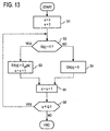
- Fig. 6 is a process flow diagram of the coefficient segment classifying part 14.
- the process by the coefficient segment classifying part 14 starts with clearing all the memories S 0 , S 1 and q to zero.
- the segment number q in the memory q is compared with the number A of coefficient segments E(q, m), and if the former is smaller than the latter, the process goes to step S3; if not, E g0 (S 0 , m) and E g1 (S 1 , m) are output as the groups E g0 and E g1 together with their sizes S 0 and S 1 , respectively, and the process ends (Step S2).
- step S3 it is determined whether the value of the classification information of the coefficient segment is 1, and if so, then the process goes to step S6, and if not to step S4.
- step S5 the group size S 0 in the memory is incremented by one and the process goes to step S8.
- step S7 the group size S 1 in the memory is incremented by one and the process goes to step S8.
- step S8 the memory counter for the segment number q is incremented by one and the process goes to step S2.
- the segment groups E g0 and E g1 classified in the coefficient classifying part 14 and their sizes S 0 , S 1 as described above are provided to the first and second quantization parts 16 and 17, respectively.
- coefficient segment classification information G(q) normally takes the value 0 or 1 with a higher probability
- any reversible compression coding schemes utilizing such a property can be used, but such entropy coding schemes as Huffman coding and arithmetic coding are particularly efficient.
- run length coding is also effective in compressing the classification information G(q).
- the first quantization part 16 encodes the coefficients that form the segment group E g0 classified in the coefficient segment classifying part 14.
- the coding may be done by: a method (A) which divides the coefficients forming the coefficient sequence C 0 into some subblocks, then adaptively allocates the number of quantization bits to each subblock, and applies scalar quantization to each subblock; a method (B) which divides the coefficients forming the coefficient sequence C 0 into some subblocks, then determines the optimum quantization step width for each subblock, and applies scalar quantization to each subblock, followed by such entropy coding as Huffman or arithmetic coding; a method (C) which applies vector quantization to the coefficient sequence C 0 in its entirety; and a method (D) which applies to interleave vector quantization to the coefficient sequence C 0 in its entirety.
- A which divides the coefficients forming the coefficient sequence C 0 into some subblocks, then adaptively allocates the number of quantization bits to each subblock, and applies scalar quantization to each subblock
- a method (B) which divides the coefficients
- the information quantized by the method A, C, or D is fed to the multiplexing part 18 after transformation of the quantization index In E0 into a bit string through binarization with the necessary and minimum number of bits.
- the bit string is provided intact to the multiplexing part 18.
- the size S 0 of the segment group E g0 from the coefficient segment classifying part 14 is also transformed into a bit string through binarization with a predetermined number of bits, thereafter being provided to the multiplexing part 18.
- the second quantization part 17 encodes the coefficients forming the segment group E g1 classified in the coefficient segment classifying part 34.
- the coding is performed following a procedure similar to that used in the first quantization part 16, the coding method need not necessarily be the same as that of the latter.
- the coding may be done by: a method (A) which divides the coefficients forming the coefficient sequence C 1 into some subblocks, then adaptively allocates the number of quantization bits to each subblock, and applies scalar quantization to each subblock; a method (B) which divides the coefficients forming the coefficient sequence C 1 into some subblocks, then determines the optimum quantiation step width for each subblock, and applies scalar quantization to each subblock, followed by such entropy coding as Huffman or arithmetic coding; a method (C) which applies vector quantization to the coefficient sequence C 1 in its entirety; and a method (D) which applies to interleave vector quantization to the coefficient sequence C 1 in its entirety.
- A which divides the coefficients forming the coefficient sequence C 1 into some subblocks, then adaptively allocates the number of quantization bits to each subblock, and applies scalar quantization to each subblock
- a method (B) which divides the coefficients forming the coefficient
- the information encoded by the method A, C, or D is fed to the multiplexing part 18 after transformation of the quantization index In E1 into a bit string through binarization with the necessary and minimum number of bits.
- the bit string is provided intact to the multiplexing part 18.
- the size S 1 of the segment group E g1 from the coefficient segment classifying part 14 is also transformed into a bit string through binarization with a predetermined number of bits, thereafter being fed to the multiplexing part 18.
- the coding method in the second quantization part 17 need not be the same as that used in the first quantization part 16. Rather, it is preferable to use different coding methods suited to the first and second quantization parts 16 and 17 based on the difference in property between the coefficient segment groups E g0 and E g1 that are provided thereto. This permits reduction of the amount of information to be coded and suppression of distortion by code errors.
- the multiplexing part 18 outputs, as a bit string or sequence, all pieces of input information G(q)*, In E0 and In E1 from the coefficient segment classification information compressing part 15 and the first and second quantization parts 16 and 17.
- the output bit sequence from the multiplexing part 18 is the output from the coding part 10, which is provided to the demultiplxing part 31 of the decoding part 30.
- the decoding part 30 will be described below.
- the demultiplexing part 31 receives the bit sequence output from the coding part 10, and follows a procedure reverse to that of multiplexing part 18 to break down the input bit sequence into bit sequences In E0 , In E1 and G(q)* for input to the first inverse-quantization part 32, the second inverse-quantization part 33 and the coefficient segment classification information decompressing part 34, respectively.
- the first inverse-quantization part 32 inverse-quantizes or reconstructs the bit sequence from the demultiplexing part 31 and outputs the coefficient segment group E g0 and its size S 0 .
- the size S 0 is reconstructed by transforming into an integer a size-indicating bit sequence binarized with a predetermined number of bits.
- the superscript "q" affixed to the symbols C 0 and E g0 indicates that since the quantization by the first quantization part 16 causes quantization errors, the decoded C 0 q and E g0 q include quantization errors with respect to C 0 and E g0 . The same applies to the superscript "q" affixed to the other symbols.
- the second inverse-quantization part 33 inverse-quantizes or reconstructs the bit sequence from the demultiplexing part 31 and outputs the coefficient segment group E G1 and its size S 1 .
- the size S 1 is reconstructed by transforming into an integer a size-indicating bit sequence binarized with a predetermined number of bits.
- the first and second quantization parts 16 and 17 in the coding part 10 use different coding methods, it is a matter of course that the first and second inverse-quantization parts 32 and 33 of the decoding part 30 use different decoding methods accordingly.
- the coefficient combining part 35 uses the coefficient segment classification information G(q) from the coefficient segment classification information decompressing part 34 to recombine the segment groups from the first and second inverse-quantization parts 32 and 33 into a single sequence and outputs frequency-domain coefficients.
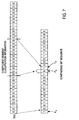
- Fig. 8 is a flowchart showing the procedure by which the coefficient combining part 35 obtains a sequence of coefficient segments E q .
- step S1 the values S 0 , S 1 and q are initialized to zeros.
- step S2 it is determined whether q is smaller than Q; if so, it is determined in step S3 whether the coefficient segment classification information G(q) is 1. If not, it is defined in step S4 that the coefficient segment E g0 q (S 0 , m) is E q (q, m), then in step S5 the value S0 is incremented by one, and in step S8 the value q is incremented by one, followed by a return to step S2.
- step S3 If it is determined in step S3 that the information G(q) is 1, the coefficient segment E g1 q (S 1 , m) is defined to be E q (q, m) in step S6, then in step S7 the value S1 is incremented by one, and in step S8 the value q is incremented by one, followed by a return to step S2.
- the frequency-time transformation part 36 frequency-time transforms the sequence of coefficients X q (q ⁇ M+m) from the coefficient combining part 35 to generate an audio signal x q , and outputs it.
- the frequency-time transform can be done by inverse discrete cosine transform (IDCT) or inverse modified discrete cosine transform (IMDCT).
- IDCT inverse discrete cosine transform
- IMDCT inverse modified discrete cosine transform
- N input coefficients are transformed into 2N time-domain samples. These samples are multiplied by a window function expressed by the following equation, after which N samples in the first half of the current frame and N samples in the latter half of the previous frame are added together to obtain N samples, which are output.
- Fig. 9 illustrates in block form a second embodiment of the present invention.
- processing parts 11, 12, 13, 14, 15, 19 and 20 constitute the coding part 10, which receives an input audio signal in the form of a sample sequence and outputs a coded bit sequence.
- Processing parts 31, 34 and 36 through 40 make up the decoding part 30, which receives the coded bit sequence and outputs an audio signal in the form of a sample sequence.
- Fig. 10 is a diagram for explaining the flattening of frequency-domain coefficients in this embodiment.
- Row A shows the state in which the frequency-domain coefficients provided from the time-frequency transformation part 11 are defined as a coefficient segment E(q, m) by the coefficient segment generating part 12.
- Rows D and E show two contiguous sequences of classified coefficient segments provided from the coefficient segment classifying part 14, that is, two coefficient segment groups E g0 and E g1 .
- the processing of the coefficient segments shown on Rows A through E is the same as in the case of the first embodiment.
- the coefficient segment groups E g0 and E g1 (Rows E and D) from the coefficient segment classifying part 14 and their sizes S 0 and S 1 are fed to the flattening/combining part 20.
- the coefficient segment classification information G(q) from the coefficient segment classification determining part 13 is also input to the flattening/combining part 20.
- the representative values L 0 and/or L 1 of the coefficient segments for the same subband for such a reason as follows:
- the coefficient values of subbands spaced one or more subbands apart in frequency are likely to greatly differ, and when they are normalized together, the flatness is not so much improved.
- the vector quantization part 19 vector quantizes the frequency-domain coefficients provided from the flattening/combining part 20, and sends a coded index In e to the multiplexing part 18.
- the vector quantization may preferably be weighted interleave vector quantization.
- the multiplexing part 18 multiplexes the coded index In e from the vector quantization part 19, together with the compressed classification information G(q)* from the coefficient segment classification information compressing part 15 and the coefficient segment flattening information L 0 * and L 1 * from the flattening/combining part 20, and sends the multiplexed output to, for instance, the decoding part 30.
- the decoding part 30 in this embodiment will be described below.
- the vector inverse-quantization part 37 inverse-quantizes, for example, by referring to a codebook, the vector quantization index In e from the demultiplexing part 31 to, uses it to obtain a sequence of flattened frequency-domain coefficients e q (q, m), and sends it to the coefficient segment generating part 38.
- the coefficient segment classifying part 39 classifies the flattened coefficient segments e q (q) into flattened coefficient segment groups e g0 q (size S 0 ) and e g1 q (size S 1 ) by the same method as in the coefficient segment classifying part 14 in the Fig. 4 embodiment.
- the frequency-time transformation part 36 transforms the entire-band coefficient segments EA(q
- Figs. 11A and 11B illustrate in block form examples of configurations of the flattening/combining part 20 and the inverse-flattening/combining part 40 in the second embodiment described above with reference to Fig. 9.
- the coefficient segment group E g0 and its size S 0 which are provided from the coefficient segment classifying part 14, are input to the first flattening part 21.
- the coefficient segment group E g0 and its size S 1 which are also provided from the coefficient segment classifying part 14, are input to the second flattening part 22.
- the first flattening part 21 flattens the coefficient segment group E g0 from the coefficient segment classifying part 14, using the coefficient segment classification information G(q) as auxiliary information.
- the flattening of the coefficient segment group E g0 is a process that calculates a representative value for each of the plural coefficient segments (subbands) and normalizes the coefficients forming all the coefficient segments of each subband by the calculated representative value.
- Fig. 12 illustrates in block form an example of the configuration of the first flattening part 21.
- the coefficient segment group EA is fed to a subband dividing part 21-2.
- step S6 it is determined whether q is smaller than Q; if so, the process returns to step S2, repeating steps S2, S3, S4 and S5. If q is not smaller than Q in step S6, restoration of the coefficient segment group E g0 to the entire band is finished.
- the sequence of coefficient segments EA expanded over the entire band is split into subbands.
- the bandwidths of the subbands may be held constant over the entire band, or may be wider in higher frequency bands.
- the coefficient segments thus split into the subbands are provided to a subband representative value calculating part 21-3 and a normalization part 21-5.
- the subband representative value calculating part 21-3 calculates the representative value for each subband.
- the representative value may be the maximum one of absolute values of the coefficients in the subband, or the square root of an average of those of the powers of the coefficients in the subband which are larger than 0. the calculated representative value is provided to a subband representative value coding part 21-4.
- the subband representative value coding part 21-4 encodes the representative value of each subband.
- the subband representative value is scalar quantized to obtain a quantized index L 0 *. If the quantized index is 0, no representative value is coded. Only representative values of quantized indexes greater than 0 are fed as the coefficient flattening information to the multiplexing part 18.
- An alternative is to apply interleave vector quantization to the representative values.
- the quantized representative values L 0 are provided to the normalization part 21-5.
- the coefficient segments E g0 split into subbands from the subband dividing part 21-2 are normalized using the quantized subband representative values generated in the subband representative coding part 21-4.
- the normalized, that is, the flattened coefficient segments e g0 are provided to a coefficient segment group reconstructing part 21-6.
- the coefficient segment group restoring part 21-6 the entire band coefficient segments normalized by reversing the procedure of the frequency band restoring part 21-1 are restored to the flattened coefficient segment group, which is output from the first flattening part 21.
- the second flattening part 22 is identical in construction to the first flattening part 21, and follows the same procedure as that of the latter to flatten the coefficient segment group E g1 fed from the coefficient segment classifying part 14, using the coefficient segment classification information G(q) as auxiliary information.
- the procedure is the same as that of the first flattening part 21, but in the steps corresponding to those of the frequency band restoring part 21-1 and the coefficient segment group restoring part 21-6 the processes for the coefficient segment classification information G(q) of the value 1 and 0 are exchanged.
- the coefficient segment group E g1 does not exist in some of the subbands, but in such subbands the flattening by the second flattening part 22 is not performed. This applies to every process by the second flattening part 22 described later on.
- the coefficient combining part 23 combines the coefficient segment groups flattened in the first and second flattening parts 21 and 22, respectively, to obtain flattened frequency-domain coefficients.
- the coefficient segment groups e g0 q and e g1 q received from the coefficient segment classifying part 39 are inverse-flattened using the decoded coefficient segment flattening information L 0 and L 1 , and in accordance wit the coefficient segment classification information G(q) these two groups of inverse-flattened coefficient segments E g0 q , E g1 q are combined into a single sequence of frequency-domain coefficients, E q (q, m), which are output from the inverse-flattening/combining part 40.
- Fig. 14 illustrates in block form the configuration of the first inverse-flattening part 41 in Fig. 11B corresponding to the first flattening part 21 in Fig. Fig. 12.
- the sequence of coefficient segments EA(q) expanded over the entire band is split into subbands.
- the bandwidths of the subbands may be held constant over the entire band, or may be wider in higher frequency bands.
- the coefficient segments split into the subbands are provided to a inverse-normalizing part 41-5.
- a subband representative value decoding part 41-4 the coefficient segment flattening information L 0 * input thereto is decoded by a decoding method corresponding to the coding method used in the subband representative value coding part 21-4 (Fig. 12) to obtain the subband representative value L 0 .
- the flattened coefficient segments e g0 q split into the subbands, provided from the subband dividing part 41-2, are inverse-normalized using the subband representative value L 0 decoded in the subband representative value decoding part 41-4.
- a coefficient segment group restoring part 41-6 the inverse-normalized coefficient segments are restored into the coefficient segment group through processing reverse to that in the frequency band restoring part 41-1, and the thus restored coefficient segment group is used as the output E g0 q from the first inverse-flattening part 41.
- the second inverse-flattening part 42 in Fig. 11B is identical in construction to the above-described first inverse-flattening part 41 in Fig. 14, and inverse-flattens the flattened coefficient segment group e g1 q , using the subband representative value L 1 derived from the flattening information L 1 * provided from the demultiplexing part 31.
- the inverse-flattening procedure is the same as that of the first inverse-flattening part 41, but in the steps corresponding to those of the frequency band restoring part 41-1 and the coefficient segment group restoring part 41-6 the processes for the coefficient segment classification information G(q) of the value 1 and 0 are exchanged.
- the coefficient segment group e g1 q does not exist in some of the subbands, but in such subbands the inverse-flattening by the second inverse-flattening part 42 is not performed. This applies to every process by the second inverse-flattening part 42 described later on.
- Fig. 12 which shows an example of the flattening part 21 (or 22) in Fig. 11A
- the coefficient segments are restored first over the entire band and then to the coefficient segment group by being flattened through normalization
- Fig. 15 depicts an example of the configuration of the flattening part 21 which directly normalizes the coefficient segment group without restoring it over the entire band.
- the subband dividing part 21-2 splits the coefficient segment group E g0 , fed from the coefficient classifying part 14 along with the size S 0 , into subbands (Row E) based on the classification information G(q) from the coefficient segment classification determining part 13, and obtain the correspondence between the subbands and the classification information G(q).
- the subband representative value calculating part 21-3 may use for each subband the square mean of absolute values of coefficient values or the square mean of coefficient values except zero.
- the subband representative value is coded in the subband representative value coding part 21-4, and the coded representative value L 1 * is provided as the coefficient flattening information to the multiplexing part 18, while at the same time the quantized subband representative value L 0 obtained by decoding is provided to the normalization part 21-5, wherein the subband coefficient segments are normalized to obtain the flattened coefficient segment group e g0 .
- the second flattening part 2 can also similarly be configured.
- Fig. 16 illustrates in block form an example of the configuration of the first inverse-flattening part 41 of the decoding part 30 that corresponds to the Fig. 15 configuration of the first flattening part 21.
- the flattened coefficient segment group e g0 q from the coefficient segment classifying part 39 (Fig. 9) is split by the subband dividing part 41-2 into subbands associated with the coefficient segment classification information G(q), thereafter being provided to the de-normalization part 41-5.
- the subband representative value decoding part 41-4 decodes the coded coefficient segment flattening information L 0 * from the demultiplexing part 31 to obtain the subband representative value L 0 , which is provided to the de-normalization part 41-5.
- the de-normalization part 41-5 inverse-normalizes the coefficient segment group e g0 q by the subband representative value L 0 corresponding to each subband, thereby obtaining the inverse-flattened coefficient segment group E g0 q .
- Figs. 17A and 17B depict other examples of the configurations of the flattening/combining part 20 and the inverse-flattening/combining part 40 in Fig. 9, respectively.
- the subregions are each formed by combining input coefficient segments belonging to the same subband when they are developed on the frequency axis.
- the subbands are preset.
- the representative value my be, for example, the maximum one of absolute values of coefficients in each subregion or an average value of the absolute values of the coefficients except 0.
- this segment sequence is the same as the sequence of coefficient segments generated by the coefficient segment generating part 12 (Fig. 9)
- the coefficient combining part 24A may be dispensed with.
- a flattening part 25 divides the sequence of coefficient segments E from the coefficient combining part 24A (or coefficient segment generating part 12) by the flattening information sequence from the flattening information combining part 23A for each q to obtain a flattened coefficient sequence over the entire band (Fig. 10, Row H).
- the thus obtained flattened coefficient sequence is provided to the vector quantization part 19 in Fig. 9.
- the inverse-flattening/combining part 40 of the decoding part 30 performs, as depicted in Fig. 17B, processing reverse to that of the flattening part 20 (Fig. 17A) of the coding part 10. That is, first and second flattening information decoding parts 41A and 42A decode the flattening information L 0 * and L 1 * from the demultiplexing part 31A and provide the subregion representative values L 0 and L 1 to a flattening information combining part 43A.
- the flattening information combining part 43A combines the flattening information L 0 and L 1 into a single sequence over the entire band based on the coefficient segment classification information G(q), and provides it to an inverse-flattening part 45.
- a coefficient combining part 44A is supplied with the flattened coefficient segment groups e g0 q and e g1 q from the coefficient segment classifying part 39 (Fig. 9), and based on the coefficient segment classification information G(q), combines the flattened coefficient segment groups e g0 q and e g1 q into a single sequence of flattened coefficient segment e q (q, m) over the entire band.
- the inverse-flattening part 45 is supplied with the single sequence of entire band flattened coefficient segment e q (q, m) and inverse-flattens it by the single sequence of entire band flattening information from the flattening information combining part 43A to generate the frequency-domain coefficients E q (q, m), which is provided to the frequency-time transformation part 36 (Fig. 9).
- Fig. 18 illustrates in block form a third embodiment of the present invention. This embodiment differs from the Fig. 9 embodiment in that a flattening part 29 is interposed between the time-frequency transformation part 11 and the coefficient segment generating part 12 in the coding part 10 and that an inverse-flattening part 49 is interposed between the inverse-flattening/combining part 40 and the frequency-time transformation part 36 in the decoding part 30.
- the flattening part 29 flattens the frequency-domain coefficient sequence from the time-frequency transformation part 11 and sends the flattened sequence of coefficient segments to the coefficient segment generating part 12.
- the flattening scheme may preferably be, for instance, normalization by linear predictive coding (LPC) spectrum.
- LPC linear predictive coding
- the linear prediction coefficient LP used to generate the LPC spectrum is encoded and sent as auxiliary information LP* to the multiplexing part 18. Subsequent processings are similar to those in Fig. 9.
- the inverse-flattening part 49 generates an LPC spectrum from a linear prediction coefficient LP obtained by decoding linear prediction coefficient information LP* fed from the demultiplexing part 31, and uses the LPC spectrum to de-flatten the coefficient sequence E q (q, m) from the inverse-flattening/combining part 40 to obtain frequency-domain coefficients, which are output to the frequency-time transformation part 36.
- the operations of the other parts are the same as in the Fig. 9 embodiment.
- the group sizes S0 and S1 need not be calculated.
- the coefficient segments has been described to be classified into two groups, but they may be classified into three or more groups. While the width of the of the coefficient segment has been described to be around 100 Hz, it may be chosen suitably under 200 Hz or so, and it is also possible to make the bandwidth narrower toward the low-frequency range. Moreover, the coefficient segments need not always be divided over the entire frequency band, and the splitting of the coefficient segments over a limited frequency range falls within the scope of the present invention.
- the first and second flattening parts 21 and 22 of the flattening/combining part 20 and the first and second inverse-flattening parts 41 and 42 of the inverse-flattening/combining part 40 may be identical in construction with the flattening part and the inverse-flattening part shown in Figs. 12 and 14, respectively, or with those shown in Figs. 15 and 16.
- the flattening/combining part 20 and the inverse-flattening part 40 in Fig. 18 may be replaced with those depicted in Figs. 17A and 17B, respectively.
- the Fig. 18 configuration with the flattening part 29 disposed between the time-frequency transformation part 11 and the coefficient segment generating part 12 can be applied to the first embodiment shown in Fig. 4.
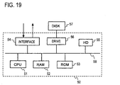
- Fig. 19 schematically depicts the configuration for practicing the coding and decoding methods of the present invention by a computer.
- the computer 50 includes CPU 51, RAM 52, ROM 53, I/O interface 54 and hard disk 55 interconnected via bus 58.
- the ROM 53 has written therein a basic program for the operation of the computer 50, and the hard disk 55 has prestored therein programs for carrying out the coding and decoding methods according to the present invention.
- the CPU 51 loads the coding program into the RAM 52 from the hard disk 55, then encodes an audio sample signal input via the interface 54 by processing it in accordance with the coding program, and outputs the coded signal via the interface 54.
- the CPU 51 loads the decoding program into the RAM 52 from the hard disk 55, then processes an input code under the control of the decoding program, and outputs he decoded audio sample signal.
- the coding/decoding programs for practicing the methods of the present invention may be program recorded on an external disk drive connected via a drive 56 to he internal bus 58.
- the recording medium with the programs for carrying out the coding and decoding methods of the present invention may be a magnetic recording medium, an IC memory, or any other recording medium such as a compact disk.
- frequency-domain coefficients are sequentially divided into plural coefficient segments each consisting of plural coefficients, then the coefficient segments are each classified into one of plural groups according to the according to the intensity of the coefficient segment, and coding is performed for each group.
- the coefficient segments of the same group have good flatness, which allows efficient coding.
Landscapes
- Engineering & Computer Science (AREA)
- Physics & Mathematics (AREA)
- Spectroscopy & Molecular Physics (AREA)
- Computational Linguistics (AREA)
- Signal Processing (AREA)
- Health & Medical Sciences (AREA)
- Audiology, Speech & Language Pathology (AREA)
- Human Computer Interaction (AREA)
- Acoustics & Sound (AREA)
- Multimedia (AREA)
- Compression, Expansion, Code Conversion, And Decoders (AREA)
- Signal Processing For Digital Recording And Reproducing (AREA)
Applications Claiming Priority (2)
| Application Number | Priority Date | Filing Date | Title |
|---|---|---|---|
| JP7706199 | 1999-03-23 | ||
| JP7706199 | 1999-03-23 |
Publications (3)
| Publication Number | Publication Date |
|---|---|
| EP1047047A2 true EP1047047A2 (fr) | 2000-10-25 |
| EP1047047A3 EP1047047A3 (fr) | 2000-11-15 |
| EP1047047B1 EP1047047B1 (fr) | 2005-02-02 |
Family
ID=13623290
Family Applications (1)
| Application Number | Title | Priority Date | Filing Date |
|---|---|---|---|
| EP00105923A Expired - Lifetime EP1047047B1 (fr) | 1999-03-23 | 2000-03-23 | Méthode et appareil de codage et décodage de signal audio et supports d'enregistrement avec des programmes à cette fin |
Country Status (3)
| Country | Link |
|---|---|
| US (1) | US6658382B1 (fr) |
| EP (1) | EP1047047B1 (fr) |
| DE (1) | DE60017825T2 (fr) |
Cited By (5)
| Publication number | Priority date | Publication date | Assignee | Title |
|---|---|---|---|---|
| WO2006121101A1 (fr) | 2005-05-13 | 2006-11-16 | Matsushita Electric Industrial Co., Ltd. | Appareil de codage audio et méthode de modification de spectre |
| WO2007008012A3 (fr) * | 2005-07-11 | 2007-03-08 | Lg Electronics Inc | Dispositif et procédé de traitement d'un signal audio |
| WO2008003467A1 (fr) * | 2006-07-04 | 2008-01-10 | Dolby Sweden Ab | Unité de filtre et procédé pour générer des réponses impulsionnelles de filtre de sous-bande |
| CN104903956A (zh) * | 2012-10-10 | 2015-09-09 | 弗兰霍菲尔运输应用研究公司 | 用于通过使用频谱模式有效合成正弦曲线和扫描的设备及方法 |
| US9135922B2 (en) | 2010-08-24 | 2015-09-15 | Lg Electronics Inc. | Method for processing audio signals, involves determining codebook index by searching for codebook corresponding to shape vector generated by using location information and spectral coefficients |
Families Citing this family (16)
| Publication number | Priority date | Publication date | Assignee | Title |
|---|---|---|---|---|
| US7272556B1 (en) * | 1998-09-23 | 2007-09-18 | Lucent Technologies Inc. | Scalable and embedded codec for speech and audio signals |
| US6978236B1 (en) * | 1999-10-01 | 2005-12-20 | Coding Technologies Ab | Efficient spectral envelope coding using variable time/frequency resolution and time/frequency switching |
| JP3881943B2 (ja) * | 2002-09-06 | 2007-02-14 | 松下電器産業株式会社 | 音響符号化装置及び音響符号化方法 |
| US7372998B2 (en) * | 2003-05-14 | 2008-05-13 | Harris Corporation | System and method for efficient non-overlapping partitioning of rectangular regions of interest in multi-channel detection |
| JP5045295B2 (ja) * | 2007-07-30 | 2012-10-10 | ソニー株式会社 | 信号処理装置及び方法、並びにプログラム |
| EP2193348A1 (fr) * | 2007-09-28 | 2010-06-09 | Voiceage Corporation | Procédé et dispositif pour une quantification efficace d'informations de transformée dans un codec de parole et d'audio incorporé |
| US20090210222A1 (en) * | 2008-02-15 | 2009-08-20 | Microsoft Corporation | Multi-Channel Hole-Filling For Audio Compression |
| WO2011048094A1 (fr) * | 2009-10-20 | 2011-04-28 | Fraunhofer-Gesellschaft zur Förderung der angewandten Forschung e.V. | Codec audio multimode et codage celp adapté à ce codec |
| CN102158692B (zh) * | 2010-02-11 | 2013-02-13 | 华为技术有限公司 | 编码方法、解码方法、编码器和解码器 |
| US9075446B2 (en) | 2010-03-15 | 2015-07-07 | Qualcomm Incorporated | Method and apparatus for processing and reconstructing data |
| CN102222505B (zh) * | 2010-04-13 | 2012-12-19 | 中兴通讯股份有限公司 | 可分层音频编解码方法系统及瞬态信号可分层编解码方法 |
| US9136980B2 (en) | 2010-09-10 | 2015-09-15 | Qualcomm Incorporated | Method and apparatus for low complexity compression of signals |
| WO2012144128A1 (fr) | 2011-04-20 | 2012-10-26 | パナソニック株式会社 | Dispositif de codage vocal/audio, dispositif de décodage vocal/audio et leurs procédés |
| JP5860145B2 (ja) | 2012-06-28 | 2016-02-16 | 株式会社日立製作所 | 無線通信による信号処理装置および方法 |
| JP6281336B2 (ja) * | 2014-03-12 | 2018-02-21 | 沖電気工業株式会社 | 音声復号化装置及びプログラム |
| EP3751567B1 (fr) | 2019-06-10 | 2022-01-26 | Axis AB | Procédé, programme informatique, codeur et dispositif de surveillance |
Family Cites Families (6)
| Publication number | Priority date | Publication date | Assignee | Title |
|---|---|---|---|---|
| US5487086A (en) * | 1991-09-13 | 1996-01-23 | Comsat Corporation | Transform vector quantization for adaptive predictive coding |
| ES2165389T3 (es) | 1993-05-31 | 2002-03-16 | Sony Corp | Aparato y metodo para codificar o descodificar señales, y medio de grabacion. |
| US5805770A (en) * | 1993-11-04 | 1998-09-08 | Sony Corporation | Signal encoding apparatus, signal decoding apparatus, recording medium, and signal encoding method |
| US5684920A (en) * | 1994-03-17 | 1997-11-04 | Nippon Telegraph And Telephone | Acoustic signal transform coding method and decoding method having a high efficiency envelope flattening method therein |
| WO1995027335A1 (fr) * | 1994-04-01 | 1995-10-12 | Sony Corporation | Methode et dispositif de codage et de decodage d'informations, methode de transmission d'informations et support d'enregistrement de l'information |
| US5950151A (en) * | 1996-02-12 | 1999-09-07 | Lucent Technologies Inc. | Methods for implementing non-uniform filters |
-
2000
- 2000-03-23 EP EP00105923A patent/EP1047047B1/fr not_active Expired - Lifetime
- 2000-03-23 US US09/534,297 patent/US6658382B1/en not_active Expired - Lifetime
- 2000-03-23 DE DE60017825T patent/DE60017825T2/de not_active Expired - Lifetime
Cited By (53)
| Publication number | Priority date | Publication date | Assignee | Title |
|---|---|---|---|---|
| CN101176147B (zh) * | 2005-05-13 | 2011-05-18 | 松下电器产业株式会社 | 语音编码装置以及频谱变形方法 |
| US8296134B2 (en) | 2005-05-13 | 2012-10-23 | Panasonic Corporation | Audio encoding apparatus and spectrum modifying method |
| WO2006121101A1 (fr) | 2005-05-13 | 2006-11-16 | Matsushita Electric Industrial Co., Ltd. | Appareil de codage audio et méthode de modification de spectre |
| EP1881487A4 (fr) * | 2005-05-13 | 2008-11-12 | Matsushita Electric Industrial Co Ltd | Appareil de codage audio et méthode de modification de spectre |
| US8121836B2 (en) | 2005-07-11 | 2012-02-21 | Lg Electronics Inc. | Apparatus and method of processing an audio signal |
| US8417100B2 (en) | 2005-07-11 | 2013-04-09 | Lg Electronics Inc. | Apparatus and method of encoding and decoding audio signal |
| US7930177B2 (en) | 2005-07-11 | 2011-04-19 | Lg Electronics Inc. | Apparatus and method of encoding and decoding audio signals using hierarchical block switching and linear prediction coding |
| US7830921B2 (en) | 2005-07-11 | 2010-11-09 | Lg Electronics Inc. | Apparatus and method of encoding and decoding audio signal |
| US7949014B2 (en) | 2005-07-11 | 2011-05-24 | Lg Electronics Inc. | Apparatus and method of encoding and decoding audio signal |
| US7962332B2 (en) | 2005-07-11 | 2011-06-14 | Lg Electronics Inc. | Apparatus and method of encoding and decoding audio signal |
| US7966190B2 (en) | 2005-07-11 | 2011-06-21 | Lg Electronics Inc. | Apparatus and method for processing an audio signal using linear prediction |
| US7987008B2 (en) | 2005-07-11 | 2011-07-26 | Lg Electronics Inc. | Apparatus and method of processing an audio signal |
| US7987009B2 (en) | 2005-07-11 | 2011-07-26 | Lg Electronics Inc. | Apparatus and method of encoding and decoding audio signals |
| US7991012B2 (en) | 2005-07-11 | 2011-08-02 | Lg Electronics Inc. | Apparatus and method of encoding and decoding audio signal |
| US7991272B2 (en) | 2005-07-11 | 2011-08-02 | Lg Electronics Inc. | Apparatus and method of processing an audio signal |
| US7996216B2 (en) | 2005-07-11 | 2011-08-09 | Lg Electronics Inc. | Apparatus and method of encoding and decoding audio signal |
| US8010372B2 (en) | 2005-07-11 | 2011-08-30 | Lg Electronics Inc. | Apparatus and method of encoding and decoding audio signal |
| US8032386B2 (en) | 2005-07-11 | 2011-10-04 | Lg Electronics Inc. | Apparatus and method of processing an audio signal |
| US8032240B2 (en) | 2005-07-11 | 2011-10-04 | Lg Electronics Inc. | Apparatus and method of processing an audio signal |
| US8032368B2 (en) | 2005-07-11 | 2011-10-04 | Lg Electronics Inc. | Apparatus and method of encoding and decoding audio signals using hierarchical block swithcing and linear prediction coding |
| US8046092B2 (en) | 2005-07-11 | 2011-10-25 | Lg Electronics Inc. | Apparatus and method of encoding and decoding audio signal |
| US8050915B2 (en) | 2005-07-11 | 2011-11-01 | Lg Electronics Inc. | Apparatus and method of encoding and decoding audio signals using hierarchical block switching and linear prediction coding |
| US8055507B2 (en) | 2005-07-11 | 2011-11-08 | Lg Electronics Inc. | Apparatus and method for processing an audio signal using linear prediction |
| US8065158B2 (en) | 2005-07-11 | 2011-11-22 | Lg Electronics Inc. | Apparatus and method of processing an audio signal |
| US8149877B2 (en) | 2005-07-11 | 2012-04-03 | Lg Electronics Inc. | Apparatus and method of encoding and decoding audio signal |
| US8108219B2 (en) | 2005-07-11 | 2012-01-31 | Lg Electronics Inc. | Apparatus and method of encoding and decoding audio signal |
| US8554568B2 (en) | 2005-07-11 | 2013-10-08 | Lg Electronics Inc. | Apparatus and method of processing an audio signal, utilizing unique offsets associated with each coded-coefficients |
| US8149878B2 (en) | 2005-07-11 | 2012-04-03 | Lg Electronics Inc. | Apparatus and method of encoding and decoding audio signal |
| US7835917B2 (en) | 2005-07-11 | 2010-11-16 | Lg Electronics Inc. | Apparatus and method of processing an audio signal |
| US8510120B2 (en) | 2005-07-11 | 2013-08-13 | Lg Electronics Inc. | Apparatus and method of processing an audio signal, utilizing unique offsets associated with coded-coefficients |
| US8149876B2 (en) | 2005-07-11 | 2012-04-03 | Lg Electronics Inc. | Apparatus and method of encoding and decoding audio signal |
| US8155144B2 (en) | 2005-07-11 | 2012-04-10 | Lg Electronics Inc. | Apparatus and method of encoding and decoding audio signal |
| US8155153B2 (en) | 2005-07-11 | 2012-04-10 | Lg Electronics Inc. | Apparatus and method of encoding and decoding audio signal |
| US8180631B2 (en) | 2005-07-11 | 2012-05-15 | Lg Electronics Inc. | Apparatus and method of processing an audio signal, utilizing a unique offset associated with each coded-coefficient |
| US8510119B2 (en) | 2005-07-11 | 2013-08-13 | Lg Electronics Inc. | Apparatus and method of processing an audio signal, utilizing unique offsets associated with coded-coefficients |
| US8255227B2 (en) | 2005-07-11 | 2012-08-28 | Lg Electronics, Inc. | Scalable encoding and decoding of multichannel audio with up to five levels in subdivision hierarchy |
| US8275476B2 (en) | 2005-07-11 | 2012-09-25 | Lg Electronics Inc. | Apparatus and method of encoding and decoding audio signals |
| WO2007008012A3 (fr) * | 2005-07-11 | 2007-03-08 | Lg Electronics Inc | Dispositif et procédé de traitement d'un signal audio |
| US8155152B2 (en) | 2005-07-11 | 2012-04-10 | Lg Electronics Inc. | Apparatus and method of encoding and decoding audio signal |
| US8326132B2 (en) | 2005-07-11 | 2012-12-04 | Lg Electronics Inc. | Apparatus and method of encoding and decoding audio signal |
| EP3739752A1 (fr) * | 2006-07-04 | 2020-11-18 | Dolby International AB | Système de filtre comprenant un convertisseur de filtre et un compresseur de filtre et procédé de fonctionnement du système de filtre |
| KR101201167B1 (ko) | 2006-07-04 | 2012-11-13 | 돌비 인터네셔널 에이비 | 압축된 서브밴드 필터 임펄스 응답들을 형성하는 필터 압축기 및 방법 |
| US8255212B2 (en) | 2006-07-04 | 2012-08-28 | Dolby International Ab | Filter compressor and method for manufacturing compressed subband filter impulse responses |
| WO2008003467A1 (fr) * | 2006-07-04 | 2008-01-10 | Dolby Sweden Ab | Unité de filtre et procédé pour générer des réponses impulsionnelles de filtre de sous-bande |
| EP3236587A1 (fr) * | 2006-07-04 | 2017-10-25 | Dolby International AB | Système de filtre comprenant un convertisseur de filtre et un compresseur de filtre et procédé de fonctionnement du système de filtre |
| EP4481731A3 (fr) * | 2006-07-04 | 2025-03-26 | Dolby International AB | Système de filtration comprenant un convertisseur de filtre et un compresseur de filtre et procédé de fonctionnement du système de filtration |
| CN101512899B (zh) * | 2006-07-04 | 2012-12-26 | 杜比国际公司 | 滤波器压缩器以及用于产生压缩子带滤波器冲激响应的方法 |
| EP3447916A1 (fr) * | 2006-07-04 | 2019-02-27 | Dolby International AB | Système de filtre comprenant un convertisseur de filtre et un compresseur de filtre et procédé de fonctionnement du système de filtre |
| EP2337224A3 (fr) * | 2006-07-04 | 2012-01-25 | Dolby International AB | Unité de à filtre et procédé pour générer des réponses impulsionnelles de filtre de sous-bande |
| EP3985873A1 (fr) * | 2006-07-04 | 2022-04-20 | Dolby International AB | Système de filtre comprenant un convertisseur de filtre et un compresseur de filtre et procédé de fonctionnement du système de filtre |
| EP4564349A3 (fr) * | 2006-07-04 | 2025-08-27 | Dolby International AB | Système de filtration comprenant un convertisseur de filtre et un compresseur de filtre et procédé de fonctionnement du système de filtration |
| US9135922B2 (en) | 2010-08-24 | 2015-09-15 | Lg Electronics Inc. | Method for processing audio signals, involves determining codebook index by searching for codebook corresponding to shape vector generated by using location information and spectral coefficients |
| CN104903956A (zh) * | 2012-10-10 | 2015-09-09 | 弗兰霍菲尔运输应用研究公司 | 用于通过使用频谱模式有效合成正弦曲线和扫描的设备及方法 |
Also Published As
| Publication number | Publication date |
|---|---|
| DE60017825D1 (de) | 2005-03-10 |
| DE60017825T2 (de) | 2006-01-12 |
| EP1047047A3 (fr) | 2000-11-15 |
| US6658382B1 (en) | 2003-12-02 |
| EP1047047B1 (fr) | 2005-02-02 |
Similar Documents
| Publication | Publication Date | Title |
|---|---|---|
| EP1047047B1 (fr) | Méthode et appareil de codage et décodage de signal audio et supports d'enregistrement avec des programmes à cette fin | |
| EP2479750B1 (fr) | Procédé pour le filtrage hiérarchique d'un signal audio et procédé pour la réconstruction hiérarchique des échantillons temporels d'un signal audio | |
| US6735339B1 (en) | Multi-stage encoding of signal components that are classified according to component value | |
| US7620554B2 (en) | Multichannel audio extension | |
| KR100803205B1 (ko) | 저비트율 오디오 신호 부호화/복호화 방법 및 장치 | |
| US7333929B1 (en) | Modular scalable compressed audio data stream | |
| JP3434260B2 (ja) | オーディオ信号符号化方法及び復号化方法、これらの装置及びプログラム記録媒体 | |
| JP3353868B2 (ja) | 音響信号変換符号化方法および復号化方法 | |
| EP0919989A1 (fr) | Codeur de signaux audio, decodeur de signaux audio, et procede de codage et de decodage de signaux audio | |
| US20040083094A1 (en) | Wavelet-based compression and decompression of audio sample sets | |
| US8019600B2 (en) | Speech signal compression and/or decompression method, medium, and apparatus | |
| Lincoln | An experimental high fidelity perceptual audio coder | |
| JP3557164B2 (ja) | オーディオ信号符号化方法及びその方法を実行するプログラム記憶媒体 | |
| JP4191503B2 (ja) | 音声楽音信号符号化方法、復号化方法、符号化装置、復号化装置、符号化プログラム、および復号化プログラム | |
| AU2011205144B2 (en) | Scalable compressed audio bit stream and codec using a hierarchical filterbank and multichannel joint coding | |
| JP3465341B2 (ja) | オーディオ信号符号化方法 | |
| JP3361790B2 (ja) | オーディオ信号符号化方法、オーディオ信号復号化方法およびオーディオ信号符号化/復号化装置と前記方法を実施するプログラムを記録した記録媒体 | |
| AU2011221401B2 (en) | Scalable compressed audio bit stream and codec using a hierarchical filterbank and multichannel joint coding | |
| Motlicek et al. | Arithmetic coding of sub-band residuals in FDLP speech/audio codec | |
| JPH1091196A (ja) | 音響信号符号化方法および音響信号復号化方法 | |
| Motlicek et al. | Entropy coding of Quantized Spectral Components in FDLP audio codec | |
| HK1171859B (en) | Method for hierarchically filtering an input audio signal and method for hierarchically reconstructing time samples of an input audio signal |
Legal Events
| Date | Code | Title | Description |
|---|---|---|---|
| PUAI | Public reference made under article 153(3) epc to a published international application that has entered the european phase |
Free format text: ORIGINAL CODE: 0009012 |
|
| PUAL | Search report despatched |
Free format text: ORIGINAL CODE: 0009013 |
|
| 17P | Request for examination filed |
Effective date: 20000323 |
|
| AK | Designated contracting states |
Kind code of ref document: A2 Designated state(s): DE FR GB |
|
| AX | Request for extension of the european patent |
Free format text: AL;LT;LV;MK;RO;SI |
|
| AK | Designated contracting states |
Kind code of ref document: A3 Designated state(s): AT BE CH CY DE DK ES FI FR GB GR IE IT LI LU MC NL PT SE |
|
| AX | Request for extension of the european patent |
Free format text: AL;LT;LV;MK;RO;SI |
|
| AKX | Designation fees paid |
Free format text: DE FR GB |
|
| 17Q | First examination report despatched |
Effective date: 20030718 |
|
| GRAP | Despatch of communication of intention to grant a patent |
Free format text: ORIGINAL CODE: EPIDOSNIGR1 |
|
| GRAS | Grant fee paid |
Free format text: ORIGINAL CODE: EPIDOSNIGR3 |
|
| GRAA | (expected) grant |
Free format text: ORIGINAL CODE: 0009210 |
|
| AK | Designated contracting states |
Kind code of ref document: B1 Designated state(s): DE FR GB |
|
| REG | Reference to a national code |
Ref country code: GB Ref legal event code: FG4D |
|
| REF | Corresponds to: |
Ref document number: 60017825 Country of ref document: DE Date of ref document: 20050310 Kind code of ref document: P |
|
| PLBE | No opposition filed within time limit |
Free format text: ORIGINAL CODE: 0009261 |
|
| STAA | Information on the status of an ep patent application or granted ep patent |
Free format text: STATUS: NO OPPOSITION FILED WITHIN TIME LIMIT |
|
| ET | Fr: translation filed | ||
| 26N | No opposition filed |
Effective date: 20051103 |
|
| REG | Reference to a national code |
Ref country code: FR Ref legal event code: PLFP Year of fee payment: 16 |
|
| PGFP | Annual fee paid to national office [announced via postgrant information from national office to epo] |
Ref country code: FR Payment date: 20150121 Year of fee payment: 16 Ref country code: GB Payment date: 20150318 Year of fee payment: 16 |
|
| PGFP | Annual fee paid to national office [announced via postgrant information from national office to epo] |
Ref country code: DE Payment date: 20150331 Year of fee payment: 16 |
|
| REG | Reference to a national code |
Ref country code: DE Ref legal event code: R119 Ref document number: 60017825 Country of ref document: DE |
|
| GBPC | Gb: european patent ceased through non-payment of renewal fee |
Effective date: 20160323 |
|
| REG | Reference to a national code |
Ref country code: FR Ref legal event code: ST Effective date: 20161130 |
|
| PG25 | Lapsed in a contracting state [announced via postgrant information from national office to epo] |
Ref country code: GB Free format text: LAPSE BECAUSE OF NON-PAYMENT OF DUE FEES Effective date: 20160323 Ref country code: FR Free format text: LAPSE BECAUSE OF NON-PAYMENT OF DUE FEES Effective date: 20160331 Ref country code: DE Free format text: LAPSE BECAUSE OF NON-PAYMENT OF DUE FEES Effective date: 20161001 |