EP1047111A2 - Kurzbogen-Entladungslampe - Google Patents
Kurzbogen-Entladungslampe Download PDFInfo
- Publication number
- EP1047111A2 EP1047111A2 EP00108395A EP00108395A EP1047111A2 EP 1047111 A2 EP1047111 A2 EP 1047111A2 EP 00108395 A EP00108395 A EP 00108395A EP 00108395 A EP00108395 A EP 00108395A EP 1047111 A2 EP1047111 A2 EP 1047111A2
- Authority
- EP
- European Patent Office
- Prior art keywords
- short
- arc discharge
- tube
- light
- sealing tube
- Prior art date
- Legal status (The legal status is an assumption and is not a legal conclusion. Google has not performed a legal analysis and makes no representation as to the accuracy of the status listed.)
- Granted
Links
Images



Classifications
-
- H—ELECTRICITY
- H01—ELECTRIC ELEMENTS
- H01J—ELECTRIC DISCHARGE TUBES OR DISCHARGE LAMPS
- H01J61/00—Gas-discharge or vapour-discharge lamps
- H01J61/02—Details
- H01J61/36—Seals between parts of vessels; Seals for leading-in conductors; Leading-in conductors
- H01J61/366—Seals for leading-in conductors
-
- G—PHYSICS
- G03—PHOTOGRAPHY; CINEMATOGRAPHY; ANALOGOUS TECHNIQUES USING WAVES OTHER THAN OPTICAL WAVES; ELECTROGRAPHY; HOLOGRAPHY
- G03F—PHOTOMECHANICAL PRODUCTION OF TEXTURED OR PATTERNED SURFACES, e.g. FOR PRINTING, FOR PROCESSING OF SEMICONDUCTOR DEVICES; MATERIALS THEREFOR; ORIGINALS THEREFOR; APPARATUS SPECIALLY ADAPTED THEREFOR
- G03F7/00—Photomechanical, e.g. photolithographic, production of textured or patterned surfaces, e.g. printing surfaces; Materials therefor, e.g. comprising photoresists; Apparatus specially adapted therefor
- G03F7/70—Microphotolithographic exposure; Apparatus therefor
- G03F7/70008—Production of exposure light, i.e. light sources
- G03F7/70016—Production of exposure light, i.e. light sources by discharge lamps
-
- H—ELECTRICITY
- H01—ELECTRIC ELEMENTS
- H01J—ELECTRIC DISCHARGE TUBES OR DISCHARGE LAMPS
- H01J61/00—Gas-discharge or vapour-discharge lamps
- H01J61/84—Lamps with discharge constricted by high pressure
- H01J61/86—Lamps with discharge constricted by high pressure with discharge additionally constricted by close spacing of electrodes, e.g. for optical projection
Definitions
- This invention concerns a short-arc type discharge lamp used for a light source in such applications as projectors, exposure or semiconductors, ultraviolet hardening and so on.
- Short-arc discharge lamps have been used, for example, as light sources in light source equipment, such as projectors or other light projection equipment.
- a cathode and anode have faced each other within a bulb made of quartz glass, in which xenon gas, for example, was sealed.
- FIG. 5 is a cross-sectional explanatory drawing that shows one example of a conventional short-arc discharge lamp.
- the bulb 30 of this short-arc discharge lamp comprises a light-emitting tube 31 to which an outwardly extending sealing tube 32 is connected at each side.
- a constricted portion 32a, which is a part of the sealing tube 32, is formed where the sealing tube 32 joins the light-emitting tube 31.
- a cathode 33 and anode 34 are located facing each other.
- the cathode 33 and the anode 34 are each mounted on the end of an electrode rod which passes through a sleeve material 35 of quartz glass, for example, and projects outward through the sealing tube 32.
- An air seal 37 is formed by fusing the end of the sealing tube 32 to the electrode rod 35.
- the sleeve material 36 is fastened in place by fusing it into a single piece with the constricted portion 32a. In this way, the electrode rod 35 is held in place by the sleeve material 36 and the end of the sealing tube 32.
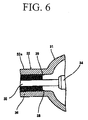
- Figure 6 is a cross-sectional explanatory drawing of a key part of the short-arc discharge lamp shown in Figure 5.
- a pendant ridge 38 formed when the constricted portion 32a of the sealing tube 32 is formed extends around the full inner circumference of the sealing tube 32 near to the end of the sleeve material 36 which is closest to the light-emitting tube 31.
- a wedge-shaped space 39 is thus formed between the pendant ridge 38 and the end of the sleeve material 36 that is closest to the light-emitting tube 31.
- the constricted portion 32a of the sealing tube 32 is formed by reducing the diameter of the sealing tube 32, by means of heating a portion of the outer periphery of the sealing tube 32 while the pressure within the bulb is reduced, for example, to between 1 x 10 -3 and 1 x 10 -4 Torr.
- the sleeve material 36 be fixed in place while preventing the constricted portion 32a of the sealing tube 32 and the sleeve material 36 from fusing into a single piece, by means of placing molybdenum foil between the sleeve material 36 and the constricted portion 32a. It has been found, however, that even with such a construction, it is not possible to completely resolve the problem described above, and cracks sometimes appear in the constricted portion when the lamp is turned on and off repeatedly.
- This invention was perfected as a result of long research to understand the causes of the problem stated above. Its purpose is to reliably prevent the appearance of cracks in the sealing tube, and thus to provide a short-arc discharge lamp with a long service life.
- the short-arc discharge lamp of this invention is one having a bulb comprising a light-emitting tube and sealing tubes connected to both sides of the light-emitting tube, with an anode and a cathode positioned facing each other within the light-emitting tube, the anode and cathode being on the ends of electrode rods that pass through sleeve material that is supported by the sealing tubes, in which short-arc discharge lamp, molybdenum foil is located between the sleeve material and the sealing tube, the outer surface of the molybdenum foil which faces the sealing tube having undergone surface treatment with a high-melting-point metal that is resistant to oxidation.
- the high-melting-point metal is preferably chosen from among tungsten, rhenium, tantalum, rhodium and platinum.
- molybdenum foil is located between the sleeve material and the sealing tube, and the outer surface of the molybdenum foil which faces the sealing tube has undergone surface treatment with a high-melting-point metal with resistance to oxidation. Because of this, the molybdenum foil does not fuse with the sealing tube, and it is possible to prevent the appearance of cracks in the sealing tube, and as a result, it is possible to obtain a short-arc discharge lamp with long service life.
- the bulb 10 in the short-arc discharge lamp of this embodiment is formed of quartz glass, and comprises an ellipsoidal light-emitting tube 11 and cylindrical sealing tubes 11 that are connected to and extend outward from opposite sides of the light-emitting tube 11. There is a constricted portion 12a on each sealing tube 12 near to where the sealing tube 12 connects to the light-emitting tube 11.
- a cathode 13 and an anode 14 are located facing each other within the light-emitting tube 11 of the bulb 10.
- Each of the cathode 13 and the anode 14 is fixed to the end of and is held in place by an electrode rod 15 made of a tungsten rod, for example.
- the electrode rod 15 extends along the center axis of the sealing tube 12, and the back end of it projects from the sealing tube 12. At the outer end of the sealing tube 12, an air seal 17 is formed by fusing the sealing tube 12 to the electrode rod 15.
- An inert gas such as xenon, argon or krypton
- a light-emitting substance such as mercury
- the pressure of the included gas will be at least 1,500 Torr when the lamp is lit, and preferably 15,000 Torr or more.
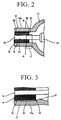
- a sleeve material 16 of quartz glass is located within the sealing tube 12. It is pierced by a through-hole 19 that is appropriate to the outer diameter of the electrode rod 15, and the electrode rod 15 passes through it. This sleeve material 16 is held in place in the constricted portion 12a of the sealing tube 12 by a pendant ridge 21 ( Figure 3) which creates a wedge-shaped space 22.
- a molybdenum foil 18 is located between the outer periphery of the sleeve material 16 and the constricted portion 12a of the sealing tube 12, and can be mounted on the outer periphery of the sleeve material 16.
- the outer surface of this molybdenum foil 18, which is in contact with the inner surface of the constricted portion 12a of the sealing tube 12, has a thin film 20 formed by surface treatment with a high-melting-point metal which is resistant to oxidation.
- the thickness of the thin film 20 formed on the surface of the molybdenum foil 18 is preferably between 0.1 and 4 ⁇ m, and the thickness of the foil itself is preferably 20 ⁇ m or less. If the thickness of the foil is greater than 20 ⁇ m, the molybdenum foil 18 becomes excessively rigid and spring-back occurs when the foil is wrapped around the outer periphery of the sleeve material 16, making application of the foil difficult.
- Such metals as tungsten, rhenium, tantalum, rhodium or platinum are specific examples of high-melting-point metals which are resistant to oxidation that can be used for surface treatment of the molybdenum foil 18.
- the method of surface treatment of the molybdenum foil 18 can be, for example, plating, vapor deposition or flame spraying.
- the molybdenum foil 18 is located between the sleeve material 16 and the constricted portion 12a of the sealing tube 12, and the outer surface of the molybdenum foil 18 that is in contact with the inner surface of the constricted portion 12a of the sealing tube 12 has been surface treated with a high-melting-point metal with resistance to oxidation. Because of this, cracks do not appear in the constricted portion 12a even in the event that pressure of the gas included in the light-emitting tube 11 is high.
- the molybdenum foil 18 has been surface treated with a high-melting point, oxidation resistant metal, no oxidation products of molybdenum are formed on the surface of the molybdenum foil 18, and even if oxidation products of the high-melting-point metal are formed, those oxidation products have low affinity for the quartz glass of the constricted portion 12a. Therefore, the molybdenum foil 18 does not fuse with the constricted portion 12a.
- the seal structure is not damaged even if the pressure of the sealed gas is high when the lamp is lit, and the lamp has a long service life.
- the effect of this is particularly prominent in discharge lamps in which the pressure of the sealed gas is 15,000 Torr or above when the lamp is lit. Accordingly, it is possible to have short-arc discharge lamps with high lighting power.
- a xenon short-arc discharge lamp with a rated power of 2 kW was built following the structure in Figure 1.
- the bulb 10 of this discharge lamp had a maximum outside diameter of 42 mm and inside volume of 53 cm 3 ;
- the sealing tube 12 had an outside diameter of 22.5 mm, inside diameter of 17.5 mm, and length of 40 mm; and
- the constricted portion 12a had an outside diameter of 20 mm, inside diameter of 12 mm, and length of 30 mm.
- the electrode rod 15 was a tungsten rod 4mm in diameter.
- the cathode 13 had a maximum outside diameter of 8.0 mm and length of 9.0 mm.
- the anode 14 had a maximum outside diameter of 10.3 mm and length of 12 mm.
- the gap between the cathode 13 and anode 14 was 3.5 mm. 15,000 Torr of xenon gas was sealed within the bulb 10.
- the sleeve material 16 was made of quartz glass with an outside diameter of 12 mm, inside diameter of 6 mm, and length of 30 mm.
- the molybdenum foil 18 was 15 ⁇ m thick, and one surface was plated with rhodium to form a thin film 0.5 ⁇ m thick; it was wrapped to the extent of 1.5 turns of the outer periphery of the sleeve material 16.
- Xenon short-arc discharge lamps were built in the same way as in test case 1, except that the molybdenum foil did not undergo surface treatment with rhodium. Ten discharge lamps built in this way were tested in the same way as in test case 1. After about 2,000 hours of aggregate operation, it was confirmed that cracks had appeared in the constricted portions of seven of the discharge lamps.
- the constricted portion was formed by reducing the diameter of a portion of the sealing tube; but, it is sometimes unnecessary to reduce the diameter of the sealing tube to hold the sleeve material in place; the effectiveness of this invention is not impaired in such cases.
- molybdenum foil is located between the sleeve material and the sealing tube, and the surface of the molybdenum foil next to the sealing tube has undergone surface treatment with a high-melting-point metal with resistance to oxidation. It is possible, by this means to prevent the appearance of cracks in the sealing tube, and accordingly it is possible to obtain short-arc discharge lamps with long service life.
Landscapes
- Physics & Mathematics (AREA)
- Engineering & Computer Science (AREA)
- Plasma & Fusion (AREA)
- General Physics & Mathematics (AREA)
- Vessels And Coating Films For Discharge Lamps (AREA)
Applications Claiming Priority (2)
| Application Number | Priority Date | Filing Date | Title |
|---|---|---|---|
| JP11682599A JP3480364B2 (ja) | 1999-04-23 | 1999-04-23 | ショートアーク型放電ランプ |
| JP11682599 | 1999-04-23 |
Publications (3)
| Publication Number | Publication Date |
|---|---|
| EP1047111A2 true EP1047111A2 (de) | 2000-10-25 |
| EP1047111A3 EP1047111A3 (de) | 2004-07-28 |
| EP1047111B1 EP1047111B1 (de) | 2008-03-26 |
Family
ID=14696569
Family Applications (1)
| Application Number | Title | Priority Date | Filing Date |
|---|---|---|---|
| EP00108395A Expired - Lifetime EP1047111B1 (de) | 1999-04-23 | 2000-04-17 | Kurzbogen-Entladungslampe |
Country Status (4)
| Country | Link |
|---|---|
| US (1) | US6433479B1 (de) |
| EP (1) | EP1047111B1 (de) |
| JP (1) | JP3480364B2 (de) |
| DE (1) | DE60038407T2 (de) |
Cited By (6)
| Publication number | Priority date | Publication date | Assignee | Title |
|---|---|---|---|---|
| US6969950B2 (en) * | 2002-04-24 | 2005-11-29 | Patent-Treuhand-Gesellschaft für elektrische Glühlampen mbH | Sealing foil and associated lamp having this foil |
| US7116023B2 (en) * | 2004-03-23 | 2006-10-03 | Emerson Electric Co. | End cap for interconnecting winding coils of a segmented stator to reduce phase-on-phase conditions and associated methods |
| WO2007133926A3 (en) * | 2006-05-12 | 2008-08-14 | Gen Electric | Foil connector for a lamp |
| WO2010124904A1 (de) * | 2009-04-30 | 2010-11-04 | Osram Gesellschaft mit beschränkter Haftung | Entladungslampe |
| CN102194643A (zh) * | 2010-03-10 | 2011-09-21 | 株式会社Orc制作所 | 放电灯 |
| DE102018207236A1 (de) * | 2018-05-09 | 2019-11-14 | Osram Gmbh | Lagerungselement mit flächig ausgebildeter schicht |
Families Citing this family (8)
| Publication number | Priority date | Publication date | Assignee | Title |
|---|---|---|---|---|
| JP3669292B2 (ja) * | 2001-06-14 | 2005-07-06 | ウシオ電機株式会社 | ショートアーク型放電ランプ |
| JP3709560B2 (ja) * | 2002-01-21 | 2005-10-26 | 日本碍子株式会社 | 高圧放電灯用組み立て体および高圧放電灯 |
| US7525252B2 (en) * | 2002-12-27 | 2009-04-28 | General Electric Company | Sealing tube material for high pressure short-arc discharge lamps |
| JP4214826B2 (ja) * | 2003-04-22 | 2009-01-28 | ウシオ電機株式会社 | ショートアーク型超高圧放電ランプ |
| US20060175973A1 (en) * | 2005-02-07 | 2006-08-10 | Lisitsyn Igor V | Xenon lamp |
| JP4702173B2 (ja) * | 2006-05-16 | 2011-06-15 | ウシオ電機株式会社 | 閃光放電ランプ装置 |
| JP5365799B2 (ja) * | 2009-10-23 | 2013-12-11 | ウシオ電機株式会社 | 高圧放電ランプおよび高圧放電ランプの製造方法 |
| JP6375944B2 (ja) * | 2014-12-26 | 2018-08-22 | 東芝ライテック株式会社 | メタルハライドランプ |
Family Cites Families (7)
| Publication number | Priority date | Publication date | Assignee | Title |
|---|---|---|---|---|
| NL7506655A (nl) * | 1975-06-05 | 1976-12-07 | Philips Nv | Korte-boog ontladingslamp. |
| HU185198B (en) * | 1982-01-28 | 1984-12-28 | Egyesuelt Izzolampa | Current inlet particularly for vacuumtechnical devices |
| USRE31519E (en) * | 1982-11-12 | 1984-02-07 | General Electric Company | Lead-in seal and lamp utilizing same |
| JPH02170338A (ja) * | 1988-12-23 | 1990-07-02 | Ushio Inc | 電極組立体 |
| DE9013735U1 (de) * | 1990-10-02 | 1992-02-06 | Patent-Treuhand-Gesellschaft für elektrische Glühlampen mbH, 8000 München | Hochdruckentladungslampe |
| US5576598A (en) * | 1995-08-31 | 1996-11-19 | Osram Sylvania Inc. | Lamp with glass sleeve and method of making same |
| JP3430887B2 (ja) * | 1997-10-31 | 2003-07-28 | ウシオ電機株式会社 | ショートアークランプ |
-
1999
- 1999-04-23 JP JP11682599A patent/JP3480364B2/ja not_active Expired - Lifetime
-
2000
- 2000-04-17 DE DE60038407T patent/DE60038407T2/de not_active Expired - Lifetime
- 2000-04-17 EP EP00108395A patent/EP1047111B1/de not_active Expired - Lifetime
- 2000-04-19 US US09/552,674 patent/US6433479B1/en not_active Expired - Lifetime
Cited By (8)
| Publication number | Priority date | Publication date | Assignee | Title |
|---|---|---|---|---|
| US6969950B2 (en) * | 2002-04-24 | 2005-11-29 | Patent-Treuhand-Gesellschaft für elektrische Glühlampen mbH | Sealing foil and associated lamp having this foil |
| US7116023B2 (en) * | 2004-03-23 | 2006-10-03 | Emerson Electric Co. | End cap for interconnecting winding coils of a segmented stator to reduce phase-on-phase conditions and associated methods |
| WO2007133926A3 (en) * | 2006-05-12 | 2008-08-14 | Gen Electric | Foil connector for a lamp |
| WO2010124904A1 (de) * | 2009-04-30 | 2010-11-04 | Osram Gesellschaft mit beschränkter Haftung | Entladungslampe |
| DE102009019526B4 (de) * | 2009-04-30 | 2025-10-23 | Osram Gmbh | Kurzbogen-Entladungslampe für Gleichstrom-Betrieb mit Drahtwendel als Dämpfungs-Führungs-Element zwischen dem Verengungsabschnitt des Lampenschafts und dem Elektrodenstab |
| CN102194643A (zh) * | 2010-03-10 | 2011-09-21 | 株式会社Orc制作所 | 放电灯 |
| CN102194643B (zh) * | 2010-03-10 | 2015-11-18 | 株式会社Orc制作所 | 放电灯 |
| DE102018207236A1 (de) * | 2018-05-09 | 2019-11-14 | Osram Gmbh | Lagerungselement mit flächig ausgebildeter schicht |
Also Published As
| Publication number | Publication date |
|---|---|
| DE60038407T2 (de) | 2009-04-09 |
| DE60038407D1 (de) | 2008-05-08 |
| JP2000306549A (ja) | 2000-11-02 |
| EP1047111A3 (de) | 2004-07-28 |
| EP1047111B1 (de) | 2008-03-26 |
| JP3480364B2 (ja) | 2003-12-15 |
| US6433479B1 (en) | 2002-08-13 |
Similar Documents
| Publication | Publication Date | Title |
|---|---|---|
| EP1047111B1 (de) | Kurzbogen-Entladungslampe | |
| US5493167A (en) | Lamp assembly with shroud employing insulator support stops | |
| EP1484784B1 (de) | Kurzbogen-Ultrahochdruck-Entladungslampe und Verfahren zur Herstellung einer solchen Lampe | |
| GB2306765A (en) | Amalgam support arrangement for an electrodeless discharge lamp | |
| US4806828A (en) | High pressure sodium discharge lamps with hydrogen getter | |
| US4625149A (en) | Metal vapor discharge lamp including an inner burner having tapered ends | |
| US7705538B2 (en) | High-pressure discharge lamp | |
| JP2004178894A (ja) | ショートアーク型放電ランプ | |
| US4658177A (en) | Electric lamp with oriented current conductors extending through a press seal | |
| US6534917B1 (en) | Mercury-filled discharge lamp with stabilized light intensity | |
| JPH05314950A (ja) | ランプ | |
| EP1387391A2 (de) | Hochdruckentladungslampe und Lampeneinheit unter Verwendung derselben | |
| EP0604221B1 (de) | Leuchtstofflampe | |
| CN101438379A (zh) | 灯用箔片连接件 | |
| US20030189406A1 (en) | Metal halide lamp with ceramic discharge vessel | |
| US20100102702A1 (en) | Component for an electric lamp with outer bulb | |
| US20030189407A1 (en) | Ultrahigh pressure mercury lamp | |
| US5051657A (en) | Safety filament assembly for double-enveloped arc discharge lamp | |
| US20100237778A1 (en) | Bushing system for a lamp | |
| JP3610908B2 (ja) | ショートアーク型超高圧放電ランプ | |
| KR20040083379A (ko) | 방전 램프 | |
| JP2000100386A (ja) | 高圧金属蒸気放電灯 | |
| JPS63241850A (ja) | 高圧放電灯 | |
| JP3384451B2 (ja) | 蛍光ランプおよび電球形蛍光ランプ | |
| JP2025031072A (ja) | ショートアーク型放電ランプおよびショートアーク型放電ランプの製造方法 |
Legal Events
| Date | Code | Title | Description |
|---|---|---|---|
| PUAI | Public reference made under article 153(3) epc to a published international application that has entered the european phase |
Free format text: ORIGINAL CODE: 0009012 |
|
| AK | Designated contracting states |
Kind code of ref document: A2 Designated state(s): AT BE CH CY DE DK ES FI FR GB GR IE IT LI LU MC NL PT SE |
|
| AX | Request for extension of the european patent |
Free format text: AL;LT;LV;MK;RO;SI |
|
| PUAL | Search report despatched |
Free format text: ORIGINAL CODE: 0009013 |
|
| AK | Designated contracting states |
Kind code of ref document: A3 Designated state(s): AT BE CH CY DE DK ES FI FR GB GR IE IT LI LU MC NL PT SE |
|
| AX | Request for extension of the european patent |
Extension state: AL LT LV MK RO SI |
|
| 17P | Request for examination filed |
Effective date: 20040630 |
|
| AKX | Designation fees paid |
Designated state(s): DE GB NL |
|
| GRAP | Despatch of communication of intention to grant a patent |
Free format text: ORIGINAL CODE: EPIDOSNIGR1 |
|
| GRAS | Grant fee paid |
Free format text: ORIGINAL CODE: EPIDOSNIGR3 |
|
| GRAA | (expected) grant |
Free format text: ORIGINAL CODE: 0009210 |
|
| AK | Designated contracting states |
Kind code of ref document: B1 Designated state(s): DE GB NL |
|
| REG | Reference to a national code |
Ref country code: GB Ref legal event code: FG4D |
|
| REF | Corresponds to: |
Ref document number: 60038407 Country of ref document: DE Date of ref document: 20080508 Kind code of ref document: P |
|
| PLBE | No opposition filed within time limit |
Free format text: ORIGINAL CODE: 0009261 |
|
| STAA | Information on the status of an ep patent application or granted ep patent |
Free format text: STATUS: NO OPPOSITION FILED WITHIN TIME LIMIT |
|
| 26N | No opposition filed |
Effective date: 20081230 |
|
| PGFP | Annual fee paid to national office [announced via postgrant information from national office to epo] |
Ref country code: NL Payment date: 20190313 Year of fee payment: 20 |
|
| PGFP | Annual fee paid to national office [announced via postgrant information from national office to epo] |
Ref country code: DE Payment date: 20190402 Year of fee payment: 20 |
|
| PGFP | Annual fee paid to national office [announced via postgrant information from national office to epo] |
Ref country code: GB Payment date: 20190417 Year of fee payment: 20 |
|
| REG | Reference to a national code |
Ref country code: DE Ref legal event code: R071 Ref document number: 60038407 Country of ref document: DE |
|
| REG | Reference to a national code |
Ref country code: NL Ref legal event code: MK Effective date: 20200416 |
|
| REG | Reference to a national code |
Ref country code: GB Ref legal event code: PE20 Expiry date: 20200416 |
|
| PG25 | Lapsed in a contracting state [announced via postgrant information from national office to epo] |
Ref country code: GB Free format text: LAPSE BECAUSE OF EXPIRATION OF PROTECTION Effective date: 20200416 |