EP1047171A1 - Dispositif d'arrêt pour tambour de câble - Google Patents
Dispositif d'arrêt pour tambour de câble Download PDFInfo
- Publication number
- EP1047171A1 EP1047171A1 EP19990123752 EP99123752A EP1047171A1 EP 1047171 A1 EP1047171 A1 EP 1047171A1 EP 19990123752 EP19990123752 EP 19990123752 EP 99123752 A EP99123752 A EP 99123752A EP 1047171 A1 EP1047171 A1 EP 1047171A1
- Authority
- EP
- European Patent Office
- Prior art keywords
- cable
- cable reel
- engaging portion
- stopper tool
- rotary drum
- Prior art date
- Legal status (The legal status is an assumption and is not a legal conclusion. Google has not performed a legal analysis and makes no representation as to the accuracy of the status listed.)
- Ceased
Links
- 238000004804 winding Methods 0.000 claims abstract description 37
- 239000011347 resin Substances 0.000 claims description 5
- 229920005989 resin Polymers 0.000 claims description 5
- 238000002360 preparation method Methods 0.000 abstract description 9
- 230000000452 restraining effect Effects 0.000 abstract description 7
- 238000010276 construction Methods 0.000 description 4
- 239000004952 Polyamide Substances 0.000 description 2
- 239000000463 material Substances 0.000 description 2
- 229920002647 polyamide Polymers 0.000 description 2
- 239000004677 Nylon Substances 0.000 description 1
- 229920002302 Nylon 6,6 Polymers 0.000 description 1
- 230000000593 degrading effect Effects 0.000 description 1
- 230000005611 electricity Effects 0.000 description 1
- 238000001125 extrusion Methods 0.000 description 1
- 238000005286 illumination Methods 0.000 description 1
- 238000000465 moulding Methods 0.000 description 1
- 229920001778 nylon Polymers 0.000 description 1
- 230000002265 prevention Effects 0.000 description 1
Images


Classifications
-
- B—PERFORMING OPERATIONS; TRANSPORTING
- B65—CONVEYING; PACKING; STORING; HANDLING THIN OR FILAMENTARY MATERIAL
- B65H—HANDLING THIN OR FILAMENTARY MATERIAL, e.g. SHEETS, WEBS, CABLES
- B65H75/00—Storing webs, tapes, or filamentary material, e.g. on reels
- B65H75/02—Cores, formers, supports, or holders for coiled, wound, or folded material, e.g. reels, spindles, bobbins, cop tubes, cans, mandrels or chucks
- B65H75/18—Constructional details
- B65H75/28—Arrangements for positively securing ends of material
- B65H75/285—Holding devices to prevent the wound material from unwinding
-
- B—PERFORMING OPERATIONS; TRANSPORTING
- B65—CONVEYING; PACKING; STORING; HANDLING THIN OR FILAMENTARY MATERIAL
- B65H—HANDLING THIN OR FILAMENTARY MATERIAL, e.g. SHEETS, WEBS, CABLES
- B65H75/00—Storing webs, tapes, or filamentary material, e.g. on reels
- B65H75/02—Cores, formers, supports, or holders for coiled, wound, or folded material, e.g. reels, spindles, bobbins, cop tubes, cans, mandrels or chucks
- B65H75/34—Cores, formers, supports, or holders for coiled, wound, or folded material, e.g. reels, spindles, bobbins, cop tubes, cans, mandrels or chucks specially adapted or mounted for storing and repeatedly paying-out and re-storing lengths of material provided for particular purposes, e.g. anchored hoses, power cables
- B65H75/38—Cores, formers, supports, or holders for coiled, wound, or folded material, e.g. reels, spindles, bobbins, cop tubes, cans, mandrels or chucks specially adapted or mounted for storing and repeatedly paying-out and re-storing lengths of material provided for particular purposes, e.g. anchored hoses, power cables involving the use of a core or former internal to, and supporting, a stored package of material
- B65H75/40—Cores, formers, supports, or holders for coiled, wound, or folded material, e.g. reels, spindles, bobbins, cop tubes, cans, mandrels or chucks specially adapted or mounted for storing and repeatedly paying-out and re-storing lengths of material provided for particular purposes, e.g. anchored hoses, power cables involving the use of a core or former internal to, and supporting, a stored package of material mobile or transportable
-
- B—PERFORMING OPERATIONS; TRANSPORTING
- B65—CONVEYING; PACKING; STORING; HANDLING THIN OR FILAMENTARY MATERIAL
- B65H—HANDLING THIN OR FILAMENTARY MATERIAL, e.g. SHEETS, WEBS, CABLES
- B65H75/00—Storing webs, tapes, or filamentary material, e.g. on reels
- B65H75/02—Cores, formers, supports, or holders for coiled, wound, or folded material, e.g. reels, spindles, bobbins, cop tubes, cans, mandrels or chucks
- B65H75/34—Cores, formers, supports, or holders for coiled, wound, or folded material, e.g. reels, spindles, bobbins, cop tubes, cans, mandrels or chucks specially adapted or mounted for storing and repeatedly paying-out and re-storing lengths of material provided for particular purposes, e.g. anchored hoses, power cables
- B65H75/38—Cores, formers, supports, or holders for coiled, wound, or folded material, e.g. reels, spindles, bobbins, cop tubes, cans, mandrels or chucks specially adapted or mounted for storing and repeatedly paying-out and re-storing lengths of material provided for particular purposes, e.g. anchored hoses, power cables involving the use of a core or former internal to, and supporting, a stored package of material
- B65H75/44—Constructional details
- B65H75/4457—Arrangements of the frame or housing
- B65H75/4468—Tubular frame
-
- H—ELECTRICITY
- H01—ELECTRIC ELEMENTS
- H01R—ELECTRICALLY-CONDUCTIVE CONNECTIONS; STRUCTURAL ASSOCIATIONS OF A PLURALITY OF MUTUALLY-INSULATED ELECTRICAL CONNECTING ELEMENTS; COUPLING DEVICES; CURRENT COLLECTORS
- H01R13/00—Details of coupling devices of the kinds covered by groups H01R12/70 or H01R24/00 - H01R33/00
- H01R13/60—Means for supporting coupling part when not engaged
-
- H—ELECTRICITY
- H02—GENERATION; CONVERSION OR DISTRIBUTION OF ELECTRIC POWER
- H02G—INSTALLATION OF ELECTRIC CABLES OR LINES, OR OF COMBINED OPTICAL AND ELECTRIC CABLES OR LINES
- H02G11/00—Arrangements of electric cables or lines between relatively-movable parts
- H02G11/02—Arrangements of electric cables or lines between relatively-movable parts using take-up reel or drum
-
- H—ELECTRICITY
- H01—ELECTRIC ELEMENTS
- H01R—ELECTRICALLY-CONDUCTIVE CONNECTIONS; STRUCTURAL ASSOCIATIONS OF A PLURALITY OF MUTUALLY-INSULATED ELECTRICAL CONNECTING ELEMENTS; COUPLING DEVICES; CURRENT COLLECTORS
- H01R25/00—Coupling parts adapted for simultaneous co-operation with two or more identical counterparts, e.g. for distributing energy to two or more circuits
Definitions
- the present invention relates to a stopper tool for a cable reel which holds back the rotation of the cable reel degrading the work efficiency and the arrayed state with loose restraining force irrespectively of whether the cable reel is used, not used or going to be used.
- a cable reel is a device from which a cable is drawn to a position to use electric power where a fixed interconnection is not provided for power supply.
- Various lengths of cables are wound and stored around the cable reel, but the length is typically in the range from several meters to several ten meters.
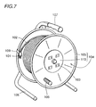
- Fig. 7 is a perspective view of a side plate of the front side of a conventional cable reel.
- This cable reel includes a cable 102, a plug 101 attached at an end of the cable, a rotary drum side plate 104 including a rim 105 and a rotary drum side surface 110, a rotary drum (only side surface 110 is shown), a receptacle 103, a handle 106 and a frame pipe 108 used as a supporting tool.
- plug 101 When the cable reel is used, plug 101 is inserted to the receptacle of a power supply which supplies power and a length of the cable necessary is drawn to the position to use power, and the plug of a appliance to use power is inserted to the receptacle 103 of the cable reel.
- cable 102 When the cable reel is not used, cable 102 is rewound by handle 106 and stored in the cable reel.
- the above described stopper tool prevents the cable from being drawn and being disarranged because of the rotation of the rotary drum when the cable is stored and not used. If the cable is drawn and used for a long time, the cable reel should be prevented from freely rotating. In the operation of drawing out the cable, or after a necessary length of the cable has been drawn, the user may stumble over and kick the cable reel for example, which could cause the cable reel to rotate and allow the cable to be drawn out.
- the stopper tool according to the above-described invention cannot prevent such rotation in the state in which the cable has been drawn.
- a desirable stopper tool in the use-preparation state after the cable has been drawn once has such loose restraining force that the stopper tool acts to restrain the rotation of the rotary drum to a certain limited extent, and may allow the length of the cable to be adjusted with prescribed force or greater force applied.
- One object of the present invention is to provide a stopper tool for cable reel which restrains the cable reel with loose restraining force from rotating irrespectively of whether it is in a state of use, non-use or use-preparation.
- a stopper tool for cable reel holds back the rotation of the rotary drum in the cable reel including a cable and includes an engaging portion provided at one end to detachably fit the rim of a side plate of the rotary drum, a winding portion provided at the other end to be wound and engaged around a component forming the cable reel in accordance with the size of the diameter of the component and a bellows portion provided between the engaging portion and the winding portion to generate tensile force when the engaging portion engages the rim of the side plate of the rotary drum and the winding portion is wound around the portion of the cable reel and engaged.
- the cable reel can be prevented from rotating irrespectively of whether the cable reel is in a state of use, non-use or use-preparation.
- a component forming the cable reel means the individual component except the side plates of the rotary drum, which constitutes the whole cable reel.
- the winding portion is desirably wound around a frame pipe, a component of the cable reel and engaged.
- the stopper tool has its engaging portion at its one end engaged to the rim of the side plate of the rotary drum, and the winding portion at the other end is wound and engaged around the frame pipe, so that the rotation of the cable reel can be prevented irrespectively of whether the cable reel is in a state of use, non-use or use-preparation.
- the prevention of the rotation may be only loosely performed for the reasons described above.
- the stopper tool for cable reel described above desirably has its winding portion wound around and engaged at the cable which is a component of the cable reel.
- the winding portion is wound around and engaged at the cable.
- the winding portion wound around and engaged at the cable desirably has a structure which can be readily wound and engaged.
- the engaging portion is formed of resin whose elasticity causes the rim of side plate of the rotary drum to be detachably fit, and the intensity of restraining force in the engagement is desirably such that the rotary drum can be rotated to draw out or rewind the cable for adjustment in the engagement state.
- an electrical appliance supplied with electricity from the cable reel, an illumination lamp, for example is to be slightly moved, the cable can be readily drawn out since the restraining force of the stopper tool is mild as described above, and yet the cable is not drawn out unlimitedly so that the arrayed state can be maintained.
- the winding portion includes a through portion through which passed is the remaining tip end after the other end is wound around the drum component and a waving surface portion having ridges and grooves on the surface extending crossing the direction in which the winding portion extends.
- the tip end of the other end wound around the component of the cable reel is passed through the through portion, and the waving surface portion engages the protruding portion provided in the through portion, so that the tip end of the other end is wound around and engaged at the component of the cable reel.
- the winding portion can be very securely wound around and engaged at the component of the cable reel, and the engagement cannot be readily released. If the same state is maintained for a long time, the above-described construction of the winding portion is particularly effective.
- the bellows portion and winding portion extend in different directions and continue at a prescribed angle.
- the engaging portion provided at one end and the winding portion provided at the other end are both engaged at the component portions of the cable reel at a prescribed distance, the bellows portion and winding portion are linearly continued so that the length of each portion can be more easily fit to the distance for attachment.
- the attachment part is not constant among different types of cable reels or even among cable reels of the same type, the bellows portion which can be freely expanded/contracted or deformed and the winding portion are continued at a prescribed angle, and therefore the engagement at both ends can be performed more easily.
- cable reels of any types can be readily prevented from rotating using a single stopper tool.
- a cable engaging portion to fit and engage a cable at the tip of one end with the engaging portion is desirably provided.
- the cable can be engaged together with the rim of the side plate of the cable reel or without engaging the rim of the cable reel. As a result, such a state where only the cable is released and disarranged during transport of the cable reel can be prevented.
- the cable reel is placed at a high position, it can be prevented that the cable is drawn downward and expanded bit by bit while withstanding the resistance of the engaging portion at the rim of the dram side plate.
- openings directed opposite to each other are desirably provided.
- the rim of the cable reel side plate can be engaged by the engaging portion from the top and then engaged by the cable engaging portion to support the cable from below.
- the cable engaging portion secures the engagement of the engaging portion by the weight of the cable and plug, and the engaging portion maintains the engagement of the cable to support the cable engaging portion.
- a cable reel includes a side plate 4 including a rim portion 5 and a rotary drum side surface 10, a rotary drum (only side surface 10 is shown), a frame pipe 8, a support frame grip portion 7, and a stopper tool 9.
- the stopper tool is manufactured by integrally molding polyamide (Nylon 66) by extrusion.
- the material of the stopper tool is not limited to polyamide, or other kinds of Nylon and resin can be employed.
- Stopper tool 9 is wound around frame pipe 8 and engaged, or its engaging portion 11 fits the rim 5 of the side plate of the cable reel in a recessed portion 15 as shown in Fig. 3.
- the remaining part of winding portion 13 is passed through through portion 22, and a waving surface portion 23 provided at the surface near the tip end is engaged with a protruding portion 24 provided at the through portion.
- the firm winding and engagement structure as described above is preferable.
- a simpler engagement structure is preferable.
- a through hole is preferably provided in the center of the tip end of the remaining part of the winding portion and a projecting portion provided at the bottom of the winding portion is passed through the through hole for engagement.
- Fig.3 shows the state in which frame pipe 8 around which the winding portion of stopper tool 9 is wound and engaged and the side plate 4 of the rotary drum is fixed with engaging portion 11 being engaged at the rim 5 of the side plate as well as the state in which the engagement is released.
- the bellows portion can be effectively expanded/contracted or deformed.
- the engagement of the engaging portion to the rim of the side plate is performed by elastic fitting by the recess 15 of resin engaging portion 11, the rotation of the side plate is allowed as long as the side plate rim is stored in the recess. Therefore, even if the stopper tool is mounted to hold back the rotation, slow and light rotation so as to allow the length of the cable to be adjusted can be made.
- the cable in this use-preparation state can be more readily arrayed and adjusted.
- the cable reel can be prevented from rotating irrespectively of whether the cable reel is in a state of use, non-use or use-preparation and yet the restraining force is mild, so that the rotation to adjust the length of the cable can be performed with the stopper tool being mounted.
- a stopper tool according to a second embodiment of the present invention includes in addition to the tool according to the first embodiment a cable engaging portion 21.
- the other construction of the cable reel is the same as the first embodiment.
- Cable engaging portion 21 has a recess 16, in which the cable is fit.
- the direction of the opening of engaging portion 11 to which the rim of the drum side plate is fit and the direction of the opening of cable engaging portion 21 are opposite to each other.
- engaging portion 11 fits the rim 5 of the drum side plate in recess 15, and cable engaging portion 21 fits cable 25 in recess 1G.
- engaging portion 11 grasps the rim 5 of the drum side plate from the top and cable engaging portion 21 grasps cable 25 so as to support the cable from below.
- engaging portion 11 can surely grasp the rim 5 of drum side plate by the weight of cable 25 and plug 26. Meanwhile, the grasping of cable 25 by cable engaging portion 21 from below can be maintained stably because engaging portion 11 is supported by the rim 5 of the drum side plate.
Landscapes
- Storage Of Web-Like Or Filamentary Materials (AREA)
- Storing, Repeated Paying-Out, And Re-Storing Of Elongated Articles (AREA)
Applications Claiming Priority (2)
| Application Number | Priority Date | Filing Date | Title |
|---|---|---|---|
| JP1999002724U JP3063304U (ja) | 1999-04-22 | 1999-04-22 | ケ―ブルドラムの止め具 |
| JP272499 | 1999-04-22 |
Publications (1)
| Publication Number | Publication Date |
|---|---|
| EP1047171A1 true EP1047171A1 (fr) | 2000-10-25 |
Family
ID=11537271
Family Applications (1)
| Application Number | Title | Priority Date | Filing Date |
|---|---|---|---|
| EP19990123752 Ceased EP1047171A1 (fr) | 1999-04-22 | 1999-11-30 | Dispositif d'arrêt pour tambour de câble |
Country Status (2)
| Country | Link |
|---|---|
| EP (1) | EP1047171A1 (fr) |
| JP (1) | JP3063304U (fr) |
Citations (6)
| Publication number | Priority date | Publication date | Assignee | Title |
|---|---|---|---|---|
| DE1829062U (de) * | 1961-01-31 | 1961-04-06 | Vliesena G M B H | Kabeltrommel. |
| DE1207176B (de) * | 1961-09-05 | 1965-12-16 | Wilhelm Sauer | Vorrichtung zum Halten des freien Endes eines elektrischen Geraetezuleitungskabels |
| EP0149072A2 (fr) * | 1984-01-13 | 1985-07-24 | Hugo Brennenstuhl GmbH & Co. KG | Tambour de câble portatif |
| JPS6331067U (fr) * | 1986-08-12 | 1988-02-29 | ||
| DE19505926A1 (de) * | 1995-02-21 | 1996-08-22 | Holzschuh Gmbh & Co Kg | Kabeltrommel |
| DE29808962U1 (de) * | 1998-05-20 | 1998-11-12 | Kess, Helmar, Dipl.-Ing., 82547 Eurasburg | Kabelbefestigung |
-
1999
- 1999-04-22 JP JP1999002724U patent/JP3063304U/ja not_active Expired - Lifetime
- 1999-11-30 EP EP19990123752 patent/EP1047171A1/fr not_active Ceased
Patent Citations (6)
| Publication number | Priority date | Publication date | Assignee | Title |
|---|---|---|---|---|
| DE1829062U (de) * | 1961-01-31 | 1961-04-06 | Vliesena G M B H | Kabeltrommel. |
| DE1207176B (de) * | 1961-09-05 | 1965-12-16 | Wilhelm Sauer | Vorrichtung zum Halten des freien Endes eines elektrischen Geraetezuleitungskabels |
| EP0149072A2 (fr) * | 1984-01-13 | 1985-07-24 | Hugo Brennenstuhl GmbH & Co. KG | Tambour de câble portatif |
| JPS6331067U (fr) * | 1986-08-12 | 1988-02-29 | ||
| DE19505926A1 (de) * | 1995-02-21 | 1996-08-22 | Holzschuh Gmbh & Co Kg | Kabeltrommel |
| DE29808962U1 (de) * | 1998-05-20 | 1998-11-12 | Kess, Helmar, Dipl.-Ing., 82547 Eurasburg | Kabelbefestigung |
Also Published As
| Publication number | Publication date |
|---|---|
| JP3063304U (ja) | 1999-10-29 |
Similar Documents
| Publication | Publication Date | Title |
|---|---|---|
| US4182005A (en) | Electrical cord holder | |
| US20080121763A1 (en) | Cable clip for organizing and routing cables and wires | |
| US4991265A (en) | Cord tie device | |
| US5075933A (en) | Cable locking and retaining device | |
| ES2269573T3 (es) | Arrollamiento de retencion para la administracion de la red de cables. | |
| US5402971A (en) | Cable tie having loop attachment | |
| CN1131684C (zh) | 可收缩的附加行李箱固定和安全系固装置及方法 | |
| US6286777B1 (en) | Extension cord storage and dispensing system | |
| US8545041B2 (en) | Mounting clip | |
| US5810525A (en) | Tool and bit band for drills | |
| US3903601A (en) | Dispenser for orthodontic chain-formed intraoral devices | |
| US5588622A (en) | Bag holder | |
| US5449067A (en) | Extension cord caddy | |
| SE454489B (sv) | Hallare for chucknyckel | |
| US20040007640A1 (en) | Units for storing flexible elongated objects | |
| US5398895A (en) | Cord holder and support | |
| US7125277B2 (en) | plug retention system | |
| WO2011134062A1 (fr) | Dispositif à cordon électrique à liberté sur 360 degrés et système associé | |
| CA2016877C (fr) | Moulinet | |
| US7077363B2 (en) | Single-handed cord/cable management device | |
| US6802471B1 (en) | Cord-attached wrap-up device | |
| US20110265290A1 (en) | Universal cable clamp | |
| EP1047171A1 (fr) | Dispositif d'arrêt pour tambour de câble | |
| US8209820B1 (en) | Cord-retaining fastener for bundled cords | |
| US6237769B1 (en) | Device to protect light strings for storage |
Legal Events
| Date | Code | Title | Description |
|---|---|---|---|
| PUAI | Public reference made under article 153(3) epc to a published international application that has entered the european phase |
Free format text: ORIGINAL CODE: 0009012 |
|
| AK | Designated contracting states |
Kind code of ref document: A1 Designated state(s): DE FR GB IT |
|
| AX | Request for extension of the european patent |
Free format text: AL;LT;LV;MK;RO;SI |
|
| 17P | Request for examination filed |
Effective date: 20010124 |
|
| 17Q | First examination report despatched |
Effective date: 20010312 |
|
| AKX | Designation fees paid |
Free format text: DE FR GB IT |
|
| GRAG | Despatch of communication of intention to grant |
Free format text: ORIGINAL CODE: EPIDOS AGRA |
|
| STAA | Information on the status of an ep patent application or granted ep patent |
Free format text: STATUS: THE APPLICATION HAS BEEN REFUSED |
|
| 18R | Application refused |
Effective date: 20020311 |