EP1047199A2 - Dispositif et méthode de transmission de données - Google Patents
Dispositif et méthode de transmission de données Download PDFInfo
- Publication number
- EP1047199A2 EP1047199A2 EP00107367A EP00107367A EP1047199A2 EP 1047199 A2 EP1047199 A2 EP 1047199A2 EP 00107367 A EP00107367 A EP 00107367A EP 00107367 A EP00107367 A EP 00107367A EP 1047199 A2 EP1047199 A2 EP 1047199A2
- Authority
- EP
- European Patent Office
- Prior art keywords
- syndrome
- error
- word
- data transmission
- code
- Prior art date
- Legal status (The legal status is an assumption and is not a legal conclusion. Google has not performed a legal analysis and makes no representation as to the accuracy of the status listed.)
- Granted
Links
Images



Classifications
-
- H—ELECTRICITY
- H03—ELECTRONIC CIRCUITRY
- H03M—CODING; DECODING; CODE CONVERSION IN GENERAL
- H03M13/00—Coding, decoding or code conversion, for error detection or error correction; Coding theory basic assumptions; Coding bounds; Error probability evaluation methods; Channel models; Simulation or testing of codes
- H03M13/65—Purpose and implementation aspects
- H03M13/6502—Reduction of hardware complexity or efficient processing
-
- H—ELECTRICITY
- H03—ELECTRONIC CIRCUITRY
- H03M—CODING; DECODING; CODE CONVERSION IN GENERAL
- H03M13/00—Coding, decoding or code conversion, for error detection or error correction; Coding theory basic assumptions; Coding bounds; Error probability evaluation methods; Channel models; Simulation or testing of codes
- H03M13/03—Error detection or forward error correction by redundancy in data representation, i.e. code words containing more digits than the source words
- H03M13/05—Error detection or forward error correction by redundancy in data representation, i.e. code words containing more digits than the source words using block codes, i.e. a predetermined number of check bits joined to a predetermined number of information bits
- H03M13/13—Linear codes
- H03M13/17—Burst error correction, e.g. error trapping, Fire codes
- H03M13/175—Error trapping or Fire codes
-
- H—ELECTRICITY
- H03—ELECTRONIC CIRCUITRY
- H03M—CODING; DECODING; CODE CONVERSION IN GENERAL
- H03M13/00—Coding, decoding or code conversion, for error detection or error correction; Coding theory basic assumptions; Coding bounds; Error probability evaluation methods; Channel models; Simulation or testing of codes
- H03M13/35—Unequal or adaptive error protection, e.g. by providing a different level of protection according to significance of source information or by adapting the coding according to the change of transmission channel characteristics
-
- H—ELECTRICITY
- H03—ELECTRONIC CIRCUITRY
- H03M—CODING; DECODING; CODE CONVERSION IN GENERAL
- H03M13/00—Coding, decoding or code conversion, for error detection or error correction; Coding theory basic assumptions; Coding bounds; Error probability evaluation methods; Channel models; Simulation or testing of codes
- H03M13/35—Unequal or adaptive error protection, e.g. by providing a different level of protection according to significance of source information or by adapting the coding according to the change of transmission channel characteristics
- H03M13/356—Unequal error protection [UEP]
Definitions
- VRC Variable Redundancy Codes
- variable redundancy codes allows the Length of the redundancy inserted by the channel coding to change dynamically. This property is particularly in Transmission channels with (temporally) variable block length of the Source and / or channel data (see e.g. UMTS (xx04 V0.5.0, UTRA FDD, multiplexing, channel coding and interleaving description) is an advantage.
- the fire codes used here are special due to their Ability to detect and / or correct bundle errors can, marked.
- the decoding of bundle error correcting Mostly, as in Error Control Coding, Fundamentals and Applications, Shu Lin / Daniel J. Castello Jr., 1983, illustrated by means of "errortrapping" Technology implemented.
- e is the period of the irreducible polynomial P (x) of degree m, where e ⁇ 2 m - 1.
- FIG. 3 is a schematic first with reference to FIG Representation of a common coding method followed by Data transmission of the coded data explained.
- 4 is a schematic Representation of a common decoding method accordingly the coding method of FIG. 3 explained.
- This error bundle E (x) is thus divided into an error bundle pattern (error burst pattern) b (x) and an error position (error position) t of this pattern b (x) from the beginning of the code block.
- FIG. 3 (c) shows the scheme for generating the transmitted code word C (x) from the k data bits D (x) and the two redundancies R 0 (x) with c bits from FIG. 3 (a) and R 1 (x ) with m bits from Fig. 3 (b).
- the two disturbed partial code words M 0 (x) and M 1 (x), each with k bits, are available to the decoder on the receiver side as input data for further processing.
- the coding can be done using a single redundancy word R (x) can be performed. In order to errors in the redundancy bit can also be corrected.
- Fig. 4 shows such a conventional in a schematic representation Decoding arrangement, which is described in Example 9.2 in Error Control Coding, Fundamentals and Applications, Shu Lin / Daniel J. Castello Jr., 1983 is explained in more detail.
- the data transmission device with the Features of claim 1 and the corresponding data transmission method according to claim 5 point over the known Approaches have the advantage that they are a special one quick and easy implementation of the coding / decoding devices offer for such a VRC code, which is particularly suitable for correcting bundle errors Codes with variable redundancy and / or data length.
- the idea on which the present invention is based is that it uses a mirroring technique.
- the mirror image version S ⁇ (x) of the syndrome pattern S (x) is used for a particularly simple and code length-independent determination of the error bundle position t.
- the mirror image of P (x), ie P * (x) is used to connect the search register. The location t of the error pattern is thereby identified. This search of the error position only requires t search cycles.
- This invention dispenses with complex arithmetic operations. There are only elementary sliding, AND, XOR, counting and Comparative operations and mirroring of register contents performed.
- the determination of the error position t is independent of the (flexible) parameters c and k.
- This invention allows easy implementation of cyclic VRC codes (variable redundancy codes).
- VRC codes variable redundancy codes.
- error detection and / or correction of VRCs are supported with low implementation complexity.
- the number of redundant bits r can exactly meet the requirements of source and channel data rate can be adjusted without that major changes to the coding and decoding architecture would be necessary.
- the length of the data block k to be coded can be exactly adapted the requirements of source and channel data rate without changing the coding and decoding architecture should be made.
- the technique of implementing the VRC code allows one flexible trade-off between error detection and error correction.
- the length of recognizable tufts of errors can be changed at any time at the expense or in favor of declining correction ability can be increased or decreased flexibly (and vice versa) without make a change to the decoding / coding architecture to have to.
- the implemented error correction and detection is easy to change and can therefore meet system requirements and / or the quality of the transmission channel can be adjusted.
- the invention thus provides an apparatus and a method for coding / decoding codes with variable Redundancy (variable redundancy codes, VRC), which allows the length of the redundancy inserted by the channel coding r dynamically change the length of the data block k dynamically change and both error detection as Correction also allowed without complex arithmetic operations to determine the bundle error pattern and its Position in the code block are required.
- VRC variable redundancy codes
- a comparison device for comparing the Error pattern with the mirrored syndrome included, where the mirrored partial polynomial as feedback / wiring is provided to the position of the error pattern identify.
- the Receiving device a first shift register for reading of the syndrome, a mirroring device for mirroring the read syndrome first shift register and a second Shift register for reading the mirrored syndrome contain.
- This implementation is particularly cheap in terms of hardware.
- the coding device is designed so that restriction of Length of the code word to the length of the period of the partial polynomial is provided. This helps further calculations to avoid.
- the coding device is designed for the length of the code word c ⁇ 2 ⁇ b - 1 applies, where b represents the length of a bundle error that can still be corrected with the help of this code and can at most take the value m, where m is the degree of the partial polynomial. Since a compromise must be made between error detection d and error correction b, small values for b are typically chosen to ensure a reasonable error detection.
- MSB denote the most significant bit and MSB the least significant bit.
- the coding process on the transmitter side runs as follows.
- FIG. 1 shows a schematic illustration of a decoding method as an embodiment of the present invention.
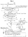
- Fig. 2 shows a schematic representation of a concrete Decoding example for the decoding method according to FIG. 1.
- register 300 The mirror image of the contents of register 300 is from now with the "lowest" m bits (from LSB to LSB + m - 1) of register 100 compared.
- Register 300, that is wired with the mirror image of P (X) is now clocked while counter 304 elapsed time (Clocks) and the comparator 303 counts both bit patterns compared with each other.
- the invention is digital in any way Suitable for data transmission.
Landscapes
- Physics & Mathematics (AREA)
- Probability & Statistics with Applications (AREA)
- Engineering & Computer Science (AREA)
- Theoretical Computer Science (AREA)
- Error Detection And Correction (AREA)
- Detection And Prevention Of Errors In Transmission (AREA)
Applications Claiming Priority (2)
| Application Number | Priority Date | Filing Date | Title |
|---|---|---|---|
| DE19918507A DE19918507A1 (de) | 1999-04-23 | 1999-04-23 | Datenübertragungsvorrichtung und -verfahren |
| DE19918507 | 1999-04-23 |
Publications (3)
| Publication Number | Publication Date |
|---|---|
| EP1047199A2 true EP1047199A2 (fr) | 2000-10-25 |
| EP1047199A3 EP1047199A3 (fr) | 2003-04-23 |
| EP1047199B1 EP1047199B1 (fr) | 2004-12-15 |
Family
ID=7905646
Family Applications (1)
| Application Number | Title | Priority Date | Filing Date |
|---|---|---|---|
| EP00107367A Expired - Lifetime EP1047199B1 (fr) | 1999-04-23 | 2000-04-05 | Dispositif et méthode de transmission de données |
Country Status (2)
| Country | Link |
|---|---|
| EP (1) | EP1047199B1 (fr) |
| DE (2) | DE19918507A1 (fr) |
Cited By (1)
| Publication number | Priority date | Publication date | Assignee | Title |
|---|---|---|---|---|
| EP1267494A3 (fr) * | 2001-06-14 | 2003-12-17 | Fanuc Ltd | Méthode de génération de configurations d'erreurs en rafales, et appareil de détection et de correction d'erreurs sur des rafales et des octets |
Families Citing this family (10)
| Publication number | Priority date | Publication date | Assignee | Title |
|---|---|---|---|---|
| RU2251814C1 (ru) * | 2003-08-18 | 2005-05-10 | Федеральное государственное унитарное предприятие "Калужский научно-исследовательский институт телемеханических устройств" | Способ передачи информации с использованием адаптивного помехоустойчивого кодирования |
| RU2276837C1 (ru) * | 2004-11-22 | 2006-05-20 | Федеральное государственное унитарное предприятие "Калужский научно-исследовательский институт телемеханических устройств" | Способ передачи информации с использованием адаптивного помехоустойчивого кодирования |
| RU2280325C1 (ru) * | 2005-02-15 | 2006-07-20 | Федеральное государственное унитарное предприятие "Калужский научно-исследовательский институт телемеханических устройств" | Способ декодирования помехоустойчивого каскадного кода переменной длины |
| RU2295196C1 (ru) * | 2005-08-01 | 2007-03-10 | Федеральное государственное унитарное предприятие "Калужский научно-исследовательский институт телемеханических устройств" | Способ контроля качества канала связи |
| RU2299515C1 (ru) * | 2005-09-19 | 2007-05-20 | Федеральное государственное унитарное предприятие "Калужский научно-исследовательский институт телемеханических устройств" | Способ передачи информации с использованием адаптивного помехоустойчивого кодирования |
| RU2327297C2 (ru) * | 2006-03-21 | 2008-06-20 | Федеральное государственное унитарное предприятие "Научно-исследовательский институт "Рубин" | Способ декодирования блоковых кодов со стираниями элементов |
| RU2319199C2 (ru) * | 2006-03-27 | 2008-03-10 | Станислав Антонович Осмоловский | Универсальный способ передачи информации с контролируемыми параметрами |
| RU2321176C1 (ru) * | 2006-06-05 | 2008-03-27 | Федеральное государственное унитарное предприятие "Калужский научно-исследовательский институт телемеханических устройств" | Способ контроля качества канала связи |
| RU2377722C2 (ru) * | 2007-06-21 | 2009-12-27 | Валерий Владимирович Золотарев | Способ декодирования помехоустойчивого кода |
| RU2369023C1 (ru) * | 2008-02-26 | 2009-09-27 | Федеральное государственное унитарное предприятие "Калужский научно-исследовательский институт телемеханических устройств" | Способ передачи и приема сообщений в системе связи |
Family Cites Families (2)
| Publication number | Priority date | Publication date | Assignee | Title |
|---|---|---|---|---|
| US3811108A (en) * | 1973-05-29 | 1974-05-14 | Honeywell Inf Systems | Reverse cyclic code error correction |
| US5381423A (en) * | 1989-07-25 | 1995-01-10 | Italtel Societa Italiana Telecomunicazioni S.P.A. | Process and device for the decoding of a shortened, cyclic binary code using error correction |
-
1999
- 1999-04-23 DE DE19918507A patent/DE19918507A1/de not_active Ceased
-
2000
- 2000-04-05 DE DE50008932T patent/DE50008932D1/de not_active Expired - Lifetime
- 2000-04-05 EP EP00107367A patent/EP1047199B1/fr not_active Expired - Lifetime
Cited By (2)
| Publication number | Priority date | Publication date | Assignee | Title |
|---|---|---|---|---|
| EP1267494A3 (fr) * | 2001-06-14 | 2003-12-17 | Fanuc Ltd | Méthode de génération de configurations d'erreurs en rafales, et appareil de détection et de correction d'erreurs sur des rafales et des octets |
| US6990625B2 (en) | 2001-06-14 | 2006-01-24 | Fanuc Ltd | Burst error pattern generation method, and burst and byte error detection correction apparatus |
Also Published As
| Publication number | Publication date |
|---|---|
| DE50008932D1 (de) | 2005-01-20 |
| DE19918507A1 (de) | 2000-10-26 |
| EP1047199B1 (fr) | 2004-12-15 |
| EP1047199A3 (fr) | 2003-04-23 |
Similar Documents
| Publication | Publication Date | Title |
|---|---|---|
| DE10133595B4 (de) | Pufferschaltung, Speicherzugriffsverfahren und Reed-Solomon-Decoder | |
| AT393926B (de) | Geraet zur feststellung und korrektur von fehlern in empfangenen digitaldatensignalen | |
| DE69019777T2 (de) | Datenstrom-Rahmensynchronisation. | |
| DE69905255T2 (de) | Verbesserte verschachteler für turbo-kodes | |
| DE102009044555B4 (de) | Verfahren und Vorrichtung zum Durchführen einer CRC-Prüfung | |
| EP0697770B1 (fr) | Procédé de décodage arithmétique | |
| DE10238841B4 (de) | Parallelverarbeitung der Decodierung und der zyklischen Redundanzüberprüfung beim Empfang von Mobilfunksignalen | |
| EP0545498B1 (fr) | Procédé et circuit pour décoder des signaux codés en RS | |
| EP1047199B1 (fr) | Dispositif et méthode de transmission de données | |
| DE2503107A1 (de) | Korrekturcode fuer impulsfehler | |
| DE69601430T2 (de) | Ver- und entschachtelung von datenelementen | |
| DE19607710A1 (de) | Verfahren und Vorrichtung zur Korrektur von Fehlern unter Verwendung mehrfacher Schätzungen | |
| DE3750456T2 (de) | Fehlerkorrigierender, bitserieller Dekodierer. | |
| EP0541161A2 (fr) | Système de transmission pour la correction d'erreurs individuelles ou en faisceau d'un signal numérique codé cycliquement | |
| EP0011749A1 (fr) | Circuit de correction de données | |
| DE69229397T2 (de) | Verfahren zur kodierung und dekodierung einer digitalen nachricht | |
| EP0567799B1 (fr) | Appareil pour la réception de données | |
| DE2906578C2 (fr) | ||
| DE3032468C2 (de) | Schaltungsanordnung zur Erkennung des Musters von Fehlerbündeln | |
| EP0293728A2 (fr) | Méthode de décodage de données | |
| DE69004801T2 (de) | Verfahren und vorrichtung zur dekodierung eines verkürzten zyklischen binärcodes mit fehlerkorrektur. | |
| DE2163105A1 (de) | Verfahren und schaltungsanordnung zum dekodieren und korrigieren eines sogenannten convolutional-code | |
| EP0748055B1 (fr) | Procédé pour le décodage de données des blocs dans un récepteur pour des signaux RDS | |
| DE4130907A1 (de) | Schaltungsanordnung zur erzeugung zyklischer codes | |
| DE3527726C2 (fr) |
Legal Events
| Date | Code | Title | Description |
|---|---|---|---|
| PUAI | Public reference made under article 153(3) epc to a published international application that has entered the european phase |
Free format text: ORIGINAL CODE: 0009012 |
|
| AK | Designated contracting states |
Kind code of ref document: A2 Designated state(s): AT BE CH CY DE DK ES FI FR GB GR IE IT LI LU MC NL PT SE |
|
| AX | Request for extension of the european patent |
Free format text: AL;LT;LV;MK;RO;SI |
|
| PUAL | Search report despatched |
Free format text: ORIGINAL CODE: 0009013 |
|
| AK | Designated contracting states |
Designated state(s): AT BE CH CY DE DK ES FI FR GB GR IE IT LI LU MC NL PT SE |
|
| AX | Request for extension of the european patent |
Extension state: AL LT LV MK RO SI |
|
| 17P | Request for examination filed |
Effective date: 20031023 |
|
| 17Q | First examination report despatched |
Effective date: 20031203 |
|
| AKX | Designation fees paid |
Designated state(s): DE FR GB IT |
|
| GRAP | Despatch of communication of intention to grant a patent |
Free format text: ORIGINAL CODE: EPIDOSNIGR1 |
|
| GRAS | Grant fee paid |
Free format text: ORIGINAL CODE: EPIDOSNIGR3 |
|
| GRAA | (expected) grant |
Free format text: ORIGINAL CODE: 0009210 |
|
| AK | Designated contracting states |
Kind code of ref document: B1 Designated state(s): DE FR GB IT |
|
| REG | Reference to a national code |
Ref country code: GB Ref legal event code: FG4D Free format text: NOT ENGLISH |
|
| REG | Reference to a national code |
Ref country code: IE Ref legal event code: FG4D Free format text: GERMAN |
|
| REF | Corresponds to: |
Ref document number: 50008932 Country of ref document: DE Date of ref document: 20050120 Kind code of ref document: P |
|
| GBT | Gb: translation of ep patent filed (gb section 77(6)(a)/1977) |
Effective date: 20050407 |
|
| PLBE | No opposition filed within time limit |
Free format text: ORIGINAL CODE: 0009261 |
|
| STAA | Information on the status of an ep patent application or granted ep patent |
Free format text: STATUS: NO OPPOSITION FILED WITHIN TIME LIMIT |
|
| ET | Fr: translation filed | ||
| 26N | No opposition filed |
Effective date: 20050916 |
|
| REG | Reference to a national code |
Ref country code: GB Ref legal event code: 732E |
|
| REG | Reference to a national code |
Ref country code: FR Ref legal event code: TP |
|
| REG | Reference to a national code |
Ref country code: FR Ref legal event code: PLFP Year of fee payment: 17 |
|
| REG | Reference to a national code |
Ref country code: FR Ref legal event code: PLFP Year of fee payment: 18 |
|
| REG | Reference to a national code |
Ref country code: FR Ref legal event code: PLFP Year of fee payment: 19 |
|
| PGFP | Annual fee paid to national office [announced via postgrant information from national office to epo] |
Ref country code: IT Payment date: 20190419 Year of fee payment: 20 |
|
| PGFP | Annual fee paid to national office [announced via postgrant information from national office to epo] |
Ref country code: FR Payment date: 20190423 Year of fee payment: 20 |
|
| PGFP | Annual fee paid to national office [announced via postgrant information from national office to epo] |
Ref country code: GB Payment date: 20190424 Year of fee payment: 20 Ref country code: DE Payment date: 20190628 Year of fee payment: 20 |
|
| REG | Reference to a national code |
Ref country code: DE Ref legal event code: R071 Ref document number: 50008932 Country of ref document: DE |
|
| REG | Reference to a national code |
Ref country code: GB Ref legal event code: PE20 Expiry date: 20200404 |
|
| PG25 | Lapsed in a contracting state [announced via postgrant information from national office to epo] |
Ref country code: GB Free format text: LAPSE BECAUSE OF EXPIRATION OF PROTECTION Effective date: 20200404 |