EP1047201B1 - CDMA Empfänger - Google Patents
CDMA Empfänger Download PDFInfo
- Publication number
- EP1047201B1 EP1047201B1 EP20000108652 EP00108652A EP1047201B1 EP 1047201 B1 EP1047201 B1 EP 1047201B1 EP 20000108652 EP20000108652 EP 20000108652 EP 00108652 A EP00108652 A EP 00108652A EP 1047201 B1 EP1047201 B1 EP 1047201B1
- Authority
- EP
- European Patent Office
- Prior art keywords
- signal
- correlation value
- reception timing
- reception
- value data
- Prior art date
- Legal status (The legal status is an assumption and is not a legal conclusion. Google has not performed a legal analysis and makes no representation as to the accuracy of the status listed.)
- Expired - Lifetime
Links
- 238000005070 sampling Methods 0.000 claims description 31
- 230000004044 response Effects 0.000 claims description 3
- 238000012545 processing Methods 0.000 description 16
- 238000012935 Averaging Methods 0.000 description 14
- 238000000034 method Methods 0.000 description 9
- 238000004891 communication Methods 0.000 description 8
- 230000005540 biological transmission Effects 0.000 description 5
- 238000010295 mobile communication Methods 0.000 description 5
- 230000007480 spreading Effects 0.000 description 5
- 230000015572 biosynthetic process Effects 0.000 description 4
- 238000010586 diagram Methods 0.000 description 4
- 238000003786 synthesis reaction Methods 0.000 description 4
- 238000013459 approach Methods 0.000 description 3
- 230000001934 delay Effects 0.000 description 3
- 230000009467 reduction Effects 0.000 description 3
- 238000012937 correction Methods 0.000 description 2
- 230000003111 delayed effect Effects 0.000 description 2
- 230000006866 deterioration Effects 0.000 description 2
- 230000008859 change Effects 0.000 description 1
- 238000001514 detection method Methods 0.000 description 1
- 230000000694 effects Effects 0.000 description 1
- 238000000605 extraction Methods 0.000 description 1
- 230000006872 improvement Effects 0.000 description 1
- 238000002360 preparation method Methods 0.000 description 1
- 238000001228 spectrum Methods 0.000 description 1
- 238000004368 synchrotron infrared microspectroscopy Methods 0.000 description 1
Images


Classifications
-
- H—ELECTRICITY
- H04—ELECTRIC COMMUNICATION TECHNIQUE
- H04B—TRANSMISSION
- H04B1/00—Details of transmission systems, not covered by a single one of groups H04B3/00 - H04B13/00; Details of transmission systems not characterised by the medium used for transmission
- H04B1/69—Spread spectrum techniques
- H04B1/707—Spread spectrum techniques using direct sequence modulation
- H04B1/7073—Synchronisation aspects
- H04B1/7075—Synchronisation aspects with code phase acquisition
- H04B1/70755—Setting of lock conditions, e.g. threshold
-
- H—ELECTRICITY
- H04—ELECTRIC COMMUNICATION TECHNIQUE
- H04B—TRANSMISSION
- H04B1/00—Details of transmission systems, not covered by a single one of groups H04B3/00 - H04B13/00; Details of transmission systems not characterised by the medium used for transmission
- H04B1/69—Spread spectrum techniques
- H04B1/707—Spread spectrum techniques using direct sequence modulation
- H04B1/7097—Interference-related aspects
- H04B1/7103—Interference-related aspects the interference being multiple access interference
- H04B1/7107—Subtractive interference cancellation
- H04B1/71075—Parallel interference cancellation
Definitions
- This invention relates to a receiver of a code-division multiple access system and, in particular, to a receiver of a code-division multiple access system intended to improve a reception quality.
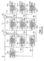
- the CDMA receiver performs an interference removing operation of a multistage type in which interference removal is repeatedly carded out in three stages for three users.
- a multiplexed signal 13 received by the CDMA receiver is supplied to the reception timing detecting section 10, the first-stage interference estimating sections 11 11 through 11 31 , and the residual signal producing section 12 1 .
- the multiplexed signal 13 is a frame signal composed of a plurality of slots. At a predetermined position in the frame, a pilot symbol as predetermined pattern data is added before or after an information symbol of a predetermined length.
- the reception timing detecting section 10 detects the pilot symbol added to the multiplexed signal 13 to detect data reception timings of desired users.
- the third-stage interference estimating sections 11 13 through 11 33 extract desired user signals for the residual signal 20 and produce demodulation signals 21 1 through 21 3 of the desired users corresponding to the user signals 16 1 through 16 3 and 18 1 through 18 3 produced by the first- and the second-stage interference estimating sections 11 11 through 11 31 and 11 12 through 11 32 , respectively.
- the residual signal 20 approaches nearer to zero than the residual signal 17 so that the third-stage interference estimating sections 11 13 through 11 33 produce the demodulation signals 21 1 through 21 3 from the added user signals after the interference is removed at maximum, respectively.
- JP-A Japanese Unexamined Patent Publication
- H10-190494 "INTERFERENCE CANCELLER AND CHANNEL ESTIMATION”.
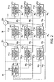
- Fig. 3 shows the characteristic part of the first-stage interference estimating sections of the CDMA receiver in Fig. 2 according to the first embodiment.
- the first-stage interference estimating sections 31 11 through 31 31 are separately illustrated in correspondence to the reception timings detected for the individual users for which simultaneous demodulation is possible.
- these sections are integrated in Fig. 3 into a first-stage interference estimating section 44 1 .
- the first-stage interference estimating section 44 1 has demodulation processing units 45 1 through 45 3 and re-spreading units 46 1 through 46 3 for the reception timings, respectively, and comprises a RAKE combining unit 47 1 and a reproduction signal producing unit 48 1 in common to all of the reception timings.
- the transmission-path estimating part 54 1 calculates transmission-path characteristic information by the use of a pilot symbol known to be preliminarily contained in the reception signal and compensates despread data with reference to the transmission-path characteristic information. Such demodulation by the demodulating portion 49 1 is carried out in synchronism with the reception timing produced by the reception timing producing portion 50 1 .
- the reception timing producing portion 50 1 produces the reception timing obtained by preliminarily compensating the processing delay of the reception timing detecting section 30 or other internal propagation delays, and further corrects the reception timing with reference to the reception timing information 35 1 . For example, the reception timing produced as mentioned above preliminarily considering the delay is used as a base and corrected with reference to the reception timing information 35 1 .
- the demodulation processing units 56 1 through 56 3 are substantially similar in structure to one another.
- the re-spreading units 57 1 through 57 3 are similar in structure to one another.
- the demodulation processing unit 56 1 comprises a demodulating portion 60 1 for demodulating an input signal, an SIR information producing portion 61 1 for measuring an SIR of the input signal to produce SIR information, and an adder portion 62 1 .
- the demodulating portion 60 1 comprises a despreading part 63 1 and a transmission-path estimating part 64 1 .
- the demodulation processing unit 56 1 further comprises a reception timing producing portion 65 1 for producing a demodulation timing of the demodulating portion.
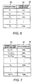
- Fig. 9 shows a characteristic part of a reception timing detecting section of the CDMA receiver according to the second embodiment of this invention. Similar parts are designated by like reference numerals as those of the reception timing detecting section 30 in Fig. 2 according to the first embodiment and the description thereof will appropriately be omitted.
- the reception timing detecting section 100 in the second embodiment has correlation value calculating units 70 1 through 70 3 for individual reception timings and comprises a spread code delay generating unit 71, a spread code producing unit 72, and a reception timing calculating unit 101 in common to all of the reception timings.
- the reception timing calculating unit 101 comprises an SIR calculating portion 102, a correlation value data averaging portion 75, and a reception timing determining portion 76.
Landscapes
- Engineering & Computer Science (AREA)
- Computer Networks & Wireless Communication (AREA)
- Signal Processing (AREA)
- Noise Elimination (AREA)
- Mobile Radio Communication Systems (AREA)
- Synchronisation In Digital Transmission Systems (AREA)
Claims (3)
- CDMA-Empfänger zum Empfangen eines Signals als Empfangssignal (33), das durch Unterziehen eines Datensignals, das ein vorgegebenes Muster aufweist, einer Spreizmodulation durch Verwendung eines Spreizcodes gegeben ist, wobei der Empfänger aufweist:Korrelationswertdaten-Erzeugungsmittel (701 - 703) zum Erzeugen von Korrelationswertdaten, die erhalten werden durch Multiplizieren des Empfangssignals mit dem Spreizcode und den vorgegebenen Musterdaten,Signal-Interferenz-Verhältnis-Berechnungsmittel (74 oder 102) zum Berechnen eines Signal-Interferenz-Verhältnisses des Empfangssignals undEmpfangszeitsetzungs-Bestimmungsmittel (36) zur Erfassung einer Empfangszeitsetzung der vorgegebenen Musterdaten in Abhängigkeit von den Korrelationswertdaten und dem Signal-Interferenz-Verhältnis, wobeidas Empfangszeitsetzungs-Bestimmungsmittel ausgelegt ist, um die Empfangszeitsetzung zu bestimmen, falls der Maximalwert der Korrelationswertdaten entsprechend der Zeitsetzung einen vorgegebenen ersten Schwellwert überschreitet und das der Zeitsetzung entsprechende Signal-Interferenz-Verhältnis, das den Maximalwert hat, einen vorgegebenen zweiten Schwellwert überschreitet.
- CDMA-Empfänger nach Anspruch 1, wobei
das Signal-Interferenz-Verhältnis-Berechnungsmittel (102) ausgelegt ist, das Signal-Interferenz-Verhältnis von dem Empfangssignal und den Korrelationswertdaten, die durch das Korrelationswertdaten-Erzeugungsmittel berechnet wurden, zu berechnen. - CDMA-Empfänger nach Anspruch 1, wobei
das Korrelationswertdaten-Erzeugungsmittel (701 - 703) ausgebildet ist, Korrelationswertdaten bei jedem Abtastpunkt innerhalb eines vorgegebenen Zeitbereichs zu erzeugen,
wobei der Empfänger ferner aufweist
Korrelationswertdaten-Speichermittel (79) zum Speichern in Übereinstimmung mit jedem Abtastpunkt, der Korrelationswertdaten, die durch die Korrelationswertdaten-Erzeugungsmittel berechnet wurden,
Signal-Interferenz-Verhältnis-Speichermittel (82) zum Erzeugen eines interpolierten Signal-Interferenz-Verhältnisses für jedes Signal-Interferenz-Verhältnis, das durch das Signal-Interferenz-Verhältnis-Berechnungsmittel berechnet wurde, für jeden Abtastpunkt innerhalb des Zeitbereichs basierend auf einer Empfangszeitsetzung, bei dem das Signal-Interferenz-Verhältnis berechnet wird, und zum Speichern der interpolierten Signal-Interferenz-Verhältnisse in Übereinstimmung mit jedem Abtastpunkt,
Auffindungsmittel zum Auffinden von maximalen Korrelationswertdaten unter den Korrelationswertdaten, die in dem Korrelationswertdaten-Speichermittel gespeichert sind,
Korrelationswertdaten-Beurteilungsmittel zum Beurteilen, ob die maximalen Korrelationswertdaten, die durch die Auffindungsmittel aufgefunden wurden, einen vorgegebenen ersten Schwellwert überschreiten, und
Verhältnisbeurteilungsmittel zum Beurteilen, wenn die Korrelationswertdaten-Beurteilungsmittel beurteilen, dass die maximalen Korrelationswertdaten den ersten Schwellwert überschreiten, ob ein bestimmtes Signal-Interferenz-Verhältnis, das in dem Signal-Interferenz-Verhältnis-Speichermittel in Übereinstimmung mit einem bestimmten Abtastpunkt der maximalen Korrelationswertdaten gespeichert sind, einen vorgegebenen zweiten Schwellwert überschreiten, wobei
das Empfangszeitsetzungsbestimmungsmittel (76) ausgebildet ist, um zu bestimmen, einer Empfangszeitsetzung entsprechend dem bestimmten Abtastpunkt als Empfangszeitsetzung der vorgegebenen Musterdaten, wenn das Verhältnisbeurteilungsmittel beurteilt, dass das bestimmte Signal-Interferenz-Verhältnis den zweiten Schwellwert überschreitet.
Applications Claiming Priority (2)
| Application Number | Priority Date | Filing Date | Title |
|---|---|---|---|
| JP11303999A JP3251261B2 (ja) | 1999-04-21 | 1999-04-21 | Cdma受信装置 |
| JP11303999 | 1999-04-21 |
Publications (3)
| Publication Number | Publication Date |
|---|---|
| EP1047201A2 EP1047201A2 (de) | 2000-10-25 |
| EP1047201A3 EP1047201A3 (de) | 2003-10-15 |
| EP1047201B1 true EP1047201B1 (de) | 2006-10-25 |
Family
ID=14601942
Family Applications (1)
| Application Number | Title | Priority Date | Filing Date |
|---|---|---|---|
| EP20000108652 Expired - Lifetime EP1047201B1 (de) | 1999-04-21 | 2000-04-20 | CDMA Empfänger |
Country Status (7)
| Country | Link |
|---|---|
| US (1) | US6804215B1 (de) |
| EP (1) | EP1047201B1 (de) |
| JP (1) | JP3251261B2 (de) |
| KR (1) | KR100364943B1 (de) |
| CN (1) | CN1115017C (de) |
| BR (1) | BR0001248A (de) |
| DE (1) | DE60031472T2 (de) |
Families Citing this family (9)
| Publication number | Priority date | Publication date | Assignee | Title |
|---|---|---|---|---|
| JP3672808B2 (ja) * | 2000-09-06 | 2005-07-20 | 松下電器産業株式会社 | 無線通信端末装置及び干渉キャンセル方法 |
| JP3473575B2 (ja) * | 2000-11-29 | 2003-12-08 | 日本電気株式会社 | Cdma移動通信装置及びそれに用いる基地局検出方法 |
| JP4572482B2 (ja) * | 2001-04-11 | 2010-11-04 | 株式会社デンソー | Cdma方式の無線通信機の復調装置 |
| JP3895228B2 (ja) * | 2002-05-07 | 2007-03-22 | 松下電器産業株式会社 | 無線通信装置および到来方向推定方法 |
| US7423976B2 (en) * | 2002-09-24 | 2008-09-09 | Interdigital Technology Corporation | Block error rate estimate reporting for target signal to interference ratio adjustment |
| JP5186748B2 (ja) * | 2006-09-29 | 2013-04-24 | 富士通株式会社 | 無線通信装置および無線通信方法 |
| US8638726B2 (en) * | 2006-11-08 | 2014-01-28 | Intel Corporation | Device, system, and method for broadcasting predefined reference maps for wireless communication |
| KR100826376B1 (ko) | 2006-11-24 | 2008-05-02 | 삼성전기주식회사 | Cdma 수신기의 매핑을 이용한 상관 방법 및 신호 처리방법 |
| US8929934B2 (en) * | 2012-04-25 | 2015-01-06 | Intel Mobile Communications GmbH | Communication devices and methods for operating a communication device |
Family Cites Families (17)
| Publication number | Priority date | Publication date | Assignee | Title |
|---|---|---|---|---|
| WO1995024086A2 (en) * | 1994-02-25 | 1995-09-08 | Philips Electronics N.V. | A multiple access digital transmission system and a radio base station and a receiver for use in such a system |
| US5642377A (en) * | 1995-07-25 | 1997-06-24 | Nokia Mobile Phones, Ltd. | Serial search acquisition system with adaptive threshold and optimal decision for spread spectrum systems |
| JP2723094B2 (ja) | 1995-11-07 | 1998-03-09 | 日本電気株式会社 | Cdma受信装置 |
| JP2798128B2 (ja) | 1996-08-06 | 1998-09-17 | 日本電気株式会社 | Cdmaマルチユーザ受信装置 |
| US6026115A (en) * | 1996-08-23 | 2000-02-15 | Ntt Mobile Communications Network, Inc. | Rake receiver |
| JP3663562B2 (ja) | 1996-12-20 | 2005-06-22 | 富士通株式会社 | 干渉キャンセラ及びチャネル推定方法 |
| US5917851A (en) | 1996-12-30 | 1999-06-29 | Nokia Telecommunications Oy | Method for allocating rake branches and rake receiver |
| US6456644B1 (en) * | 1997-06-23 | 2002-09-24 | Cellnet Data Systems, Inc. | Bandpass correlation of a spread spectrum signal |
| US6363049B1 (en) * | 1998-03-25 | 2002-03-26 | Sony Corporation | Adaptive acquisition system for CDMA and spread spectrum systems compensating for frequency offset and noise |
| JP3891373B2 (ja) | 1998-03-26 | 2007-03-14 | ソニー株式会社 | 復調装置及び復調方法 |
| JP3024750B2 (ja) * | 1998-04-07 | 2000-03-21 | 日本電気株式会社 | Ds−cdmaマルチユーザ干渉キャンセラ装置及びds−cdma通信システム |
| US6229842B1 (en) * | 1998-07-16 | 2001-05-08 | Telefonaktiebolaget Lm Ericsson (Publ) | Adaptive path selection threshold setting for DS-CDMA receivers |
| JP2991196B1 (ja) | 1998-08-24 | 1999-12-20 | 日本電気株式会社 | Cdma受信方法および受信機 |
| JP3967472B2 (ja) | 1998-09-07 | 2007-08-29 | 富士通株式会社 | Cdma受信機 |
| JP3156783B2 (ja) | 1999-01-21 | 2001-04-16 | 日本電気株式会社 | スペクトラム拡散通信システムにおける同期捕捉装置および同期捕捉方法 |
| US6501788B1 (en) * | 1999-01-22 | 2002-12-31 | Ericsson Inc. | Apparatus and methods for intereference cancellation in spread spectrum communications systems |
| JP3930187B2 (ja) * | 1999-03-03 | 2007-06-13 | 株式会社日立コミュニケーションテクノロジー | 同期制御方法、受信機、基地局及び移動端末 |
-
1999
- 1999-04-21 JP JP11303999A patent/JP3251261B2/ja not_active Expired - Fee Related
-
2000
- 2000-04-20 KR KR1020000020874A patent/KR100364943B1/ko not_active Expired - Fee Related
- 2000-04-20 BR BR0001248A patent/BR0001248A/pt not_active IP Right Cessation
- 2000-04-20 US US09/553,476 patent/US6804215B1/en not_active Expired - Fee Related
- 2000-04-20 EP EP20000108652 patent/EP1047201B1/de not_active Expired - Lifetime
- 2000-04-20 DE DE2000631472 patent/DE60031472T2/de not_active Expired - Fee Related
- 2000-04-21 CN CN00105946A patent/CN1115017C/zh not_active Expired - Fee Related
Also Published As
| Publication number | Publication date |
|---|---|
| BR0001248A (pt) | 2000-10-31 |
| US6804215B1 (en) | 2004-10-12 |
| DE60031472T2 (de) | 2007-08-23 |
| KR100364943B1 (ko) | 2002-12-16 |
| EP1047201A2 (de) | 2000-10-25 |
| DE60031472D1 (de) | 2006-12-07 |
| JP3251261B2 (ja) | 2002-01-28 |
| CN1271222A (zh) | 2000-10-25 |
| CN1115017C (zh) | 2003-07-16 |
| KR20000071750A (ko) | 2000-11-25 |
| EP1047201A3 (de) | 2003-10-15 |
| JP2000307475A (ja) | 2000-11-02 |
Similar Documents
| Publication | Publication Date | Title |
|---|---|---|
| US6067315A (en) | Method and apparatus for coherently-averaged power estimation | |
| KR100212306B1 (ko) | 코드 분할 다중 접속(cdma) 복조 장치 | |
| EP1235360B1 (de) | Kommunikationsengerät und demodulationsverfahren | |
| KR100263977B1 (ko) | 멀티스테이지형 간섭 상쇄기 | |
| US6272167B1 (en) | Spread spectrum communication system | |
| JP3228405B2 (ja) | 直接拡散cdma伝送方式の受信機 | |
| JPH08237190A (ja) | チャンネル評価方法及び受信機 | |
| JPH1051424A (ja) | Cdma復調装置 | |
| EP1047201B1 (de) | CDMA Empfänger | |
| US7167505B2 (en) | Radio receiving apparatus and radio receiving method | |
| EP1134916B1 (de) | Verfahren zum Erfassen der Synchronisation eines Zeitschlitzes in einem Direkt-Sequenz-Spreizspektrum-Kommunikationsempfänger | |
| KR100395384B1 (ko) | 간단한 구성을 갖는 수신기의 복조 | |
| JPH08335899A (ja) | Cdma復調回路 | |
| JP2003347968A (ja) | パス位置検出方法およびcdma受信装置 | |
| JP2991236B1 (ja) | 直接拡散受信デ―タの誤り推定装置および直接拡散受信装置 | |
| KR100326158B1 (ko) | 코드분할다중처리 이동통신시스템의 수신기의 채널 추정 보상장치 | |
| EP1041726B1 (de) | Empfangsgerät eines Spreizspektrumnachrichtenübertragungssystems | |
| JP2000307469A (ja) | スペクトル拡散型受信装置及び方法 | |
| JP2002319877A (ja) | Rake受信装置 | |
| JP2001024553A (ja) | Cdma受信装置の干渉キャンセラ装置 | |
| JP2003318780A (ja) | パス補足方法及びこの方法を利用するcdma受信装置 | |
| JP2003124845A (ja) | 受信装置および受信方法 | |
| JPWO1996042146A1 (ja) | Cdma復調装置 | |
| JP2003163613A (ja) | 受信装置及び受信方法 |
Legal Events
| Date | Code | Title | Description |
|---|---|---|---|
| PUAI | Public reference made under article 153(3) epc to a published international application that has entered the european phase |
Free format text: ORIGINAL CODE: 0009012 |
|
| AK | Designated contracting states |
Kind code of ref document: A2 Designated state(s): AT BE CH CY DE DK ES FI FR GB GR IE IT LI LU MC NL PT SE |
|
| AX | Request for extension of the european patent |
Free format text: AL;LT;LV;MK;RO;SI |
|
| PUAL | Search report despatched |
Free format text: ORIGINAL CODE: 0009013 |
|
| AK | Designated contracting states |
Kind code of ref document: A3 Designated state(s): AT BE CH CY DE DK ES FI FR GB GR IE IT LI LU MC NL PT SE |
|
| AX | Request for extension of the european patent |
Extension state: AL LT LV MK RO SI |
|
| 17P | Request for examination filed |
Effective date: 20030904 |
|
| 17Q | First examination report despatched |
Effective date: 20031117 |
|
| AKX | Designation fees paid |
Designated state(s): DE GB |
|
| GRAP | Despatch of communication of intention to grant a patent |
Free format text: ORIGINAL CODE: EPIDOSNIGR1 |
|
| GRAJ | Information related to disapproval of communication of intention to grant by the applicant or resumption of examination proceedings by the epo deleted |
Free format text: ORIGINAL CODE: EPIDOSDIGR1 |
|
| GRAP | Despatch of communication of intention to grant a patent |
Free format text: ORIGINAL CODE: EPIDOSNIGR1 |
|
| GRAS | Grant fee paid |
Free format text: ORIGINAL CODE: EPIDOSNIGR3 |
|
| GRAA | (expected) grant |
Free format text: ORIGINAL CODE: 0009210 |
|
| AK | Designated contracting states |
Kind code of ref document: B1 Designated state(s): DE GB |
|
| REG | Reference to a national code |
Ref country code: GB Ref legal event code: FG4D |
|
| REF | Corresponds to: |
Ref document number: 60031472 Country of ref document: DE Date of ref document: 20061207 Kind code of ref document: P |
|
| PLBE | No opposition filed within time limit |
Free format text: ORIGINAL CODE: 0009261 |
|
| STAA | Information on the status of an ep patent application or granted ep patent |
Free format text: STATUS: NO OPPOSITION FILED WITHIN TIME LIMIT |
|
| 26N | No opposition filed |
Effective date: 20070726 |
|
| PGFP | Annual fee paid to national office [announced via postgrant information from national office to epo] |
Ref country code: DE Payment date: 20090420 Year of fee payment: 10 |
|
| PGFP | Annual fee paid to national office [announced via postgrant information from national office to epo] |
Ref country code: GB Payment date: 20090415 Year of fee payment: 10 |
|
| GBPC | Gb: european patent ceased through non-payment of renewal fee |
Effective date: 20100420 |
|
| PG25 | Lapsed in a contracting state [announced via postgrant information from national office to epo] |
Ref country code: DE Free format text: LAPSE BECAUSE OF NON-PAYMENT OF DUE FEES Effective date: 20101103 |
|
| PG25 | Lapsed in a contracting state [announced via postgrant information from national office to epo] |
Ref country code: GB Free format text: LAPSE BECAUSE OF NON-PAYMENT OF DUE FEES Effective date: 20100420 |