EP1047284A2 - Elektroakustischer Wandler für extreme Druckbelastungen - Google Patents
Elektroakustischer Wandler für extreme Druckbelastungen Download PDFInfo
- Publication number
- EP1047284A2 EP1047284A2 EP00890125A EP00890125A EP1047284A2 EP 1047284 A2 EP1047284 A2 EP 1047284A2 EP 00890125 A EP00890125 A EP 00890125A EP 00890125 A EP00890125 A EP 00890125A EP 1047284 A2 EP1047284 A2 EP 1047284A2
- Authority
- EP
- European Patent Office
- Prior art keywords
- membrane
- converter according
- support
- area
- central part
- Prior art date
- Legal status (The legal status is an assumption and is not a legal conclusion. Google has not performed a legal analysis and makes no representation as to the accuracy of the status listed.)
- Withdrawn
Links
Images
Classifications
-
- H—ELECTRICITY
- H04—ELECTRIC COMMUNICATION TECHNIQUE
- H04R—LOUDSPEAKERS, MICROPHONES, GRAMOPHONE PICK-UPS OR LIKE ACOUSTIC ELECTROMECHANICAL TRANSDUCERS; ELECTRIC HEARING AIDS; PUBLIC ADDRESS SYSTEMS
- H04R9/00—Transducers of moving-coil, moving-strip, or moving-wire type
- H04R9/06—Loudspeakers
Definitions
- the invention relates to an electroacoustic transducer with a membrane that has a central part and an edge part and one directly at their transition area or indirectly attached coil in an annular Gap between two yoke parts of a magnet system for extreme pressure loads.
- Electroacoustic transducers especially those for portable ones Phones essentially consist of a capsule, which in turn consists of an upper part and a lower part, from a magnet with a mostly two-part Yoke and a membrane that carries a coil.
- the membrane is usually essentially ring-shaped Edge part and a dome-shaped or dome-shaped central part to distinguish.
- the membrane is with her fixed outer edge, mostly between the upper and the Lower part of the capsule clamped or glued on.
- the coil is attached in the area of the membrane in which the edge part with the central part comes together.
- the attachment can be directly on the membrane or on a coil carrier (if necessary through special training the membrane can be omitted in this area).
- the coil extends into a circular slot between the Yoke parts of the magnet, making the electro-acoustic Depending on the design, transducers as microphones or loudspeakers works.
- the invention aims to be an electroacoustic To create converters that do not have the disadvantages shown has and both against extreme pressure surges as is also stable against water.
- these objects are achieved in that water-resistant material known per se as membrane material Plastic such as polycarbonate, polyetherester urethane or PETP film, for example Mylar, is used and that at least in the central part of the membrane between the membrane and the underlying yoke part a mechanical support is provided at a distance from the membrane.
- membrane material Plastic such as polycarbonate, polyetherester urethane or PETP film, for example Mylar
- a mechanical support is provided at a distance from the membrane.
- the distance of the membrane from the support in the "idle state" - equal pressure on both sides of the membrane - must be larger than the largest in normal operation deflection of the membrane. This deflection can with knowledge of the membrane used and its mechanical Reaction to sound waves (microphone) or to the largest intended currents (loudspeakers or ear capsule) can be easily calculated by a specialist.
- this distance be smaller than there is an irreversible deformation of the Membrane corresponds.
- This value is also known to the Invention by a specialist in an envisaged membrane easy to calculate or with a few simple ones Try to determine.
- that between the Both boundaries available area is relatively large is and that no disadvantages occur when the mechanical Support until it is relatively close to the membrane.
- the mechanical support does not have to be the whole, under cover the central part of the membrane, but can have a preferably circular area in the Center capture, its diameter between 20%, preferred 40%, and 80% of the diameter of the one under the central part of the membrane lying yoke part. In order to the support surface reached (in the projection) is between 4%, preferably 16%, and particularly preferably 64% this area.
- the mechanical support surface can depend on the desired acoustic influence on the transducer his. So it is possible to change the contact area (below in this description the area of both the membrane as well as the support surface understood that with each other come into contact) “dense” or “permeable”.
- Dense means any essentially airtight Contact area, under permeable any air permeable Contact area.
- permeable contact surfaces are grids or sieve-like structures, scaffold-like Struts (similar to an umbrella frame) and the like, dense contact areas are for example To achieve platelets made of plastic or metal.
- the mechanical support becomes an acoustic friction set the characteristic in a predictable manner of the converter. It is according to the invention in this way possible, desired characteristics by an appropriate Design of the mechanical support better to achieve than before or at all for the first time.
- annular edge part of the membrane with a corresponding one mechanical support.
- This is essentially toroidal and has one of the undeformed Edge zone roughly corresponding shape of their contact surface on. What in this description about the central part the membrane is said to be mutatis mutandis also for their marginal part.
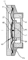
- An electroacoustic transducer has one from an upper part 1 and a lower part 2 existing capsule.
- a magnet 3 on a lower yoke part 4 stored and carries an upper yoke part 5.
- the lower Yoke part 4 has a bowl shape with a retracted upper edge. Between the two yoke parts 4, 5 remain an annular Gap free.
- a membrane 6 is between the two capsule parts 1, 2 pinched and / or glued.
- the membrane 6 has one Edge part 7 and a central part 8.
- a coil 9 is attached, for example glued. This coil protrudes into the annular gap between the two Yoke parts 4, 5.
- a mechanical support 10 In the space below the central part 8 of the membrane 6 a mechanical support 10 according to the invention is provided.
- this has Support 10 in the shape of a mushroom, i.e. she is with a central foot, with which they on the yoke part 5 attached, for example glued.
- the yoke part 5 is usually circular, since it together with the yoke part 4 forms a circular slot into which the coil 9 projects.
- the Size of the area of the yoke part 5 corresponds to the same reason practically completely the area of the Central parts 8 of the membrane 6, so that between the two Areas or their sizes do not have to be differentiated.
- the diameter is the circular support 10 almost 100% of Diameter of the yoke part 5, but this is as above executed, not necessary.
- the support 10 is in the embodiment shown represented by a solid line, but this is not Reference to the selected permeability of the contact surface. As indicated above, this permeability can be extended Limits can be chosen freely or depending on the desired acoustic characteristics can be selected.
- the edge part no supports are provided for the membrane, but it is easy for the person skilled in the art, also to place a support in this area.
- the capsule part 2 made of plastic can be one Support, e.g. in the form of radial ribs, in one piece with the capsule part 2, thus practically without Additional costs to be manufactured.
- the membrane 6 shown and in particular the type of Attachment of the coil 9 to the membrane corresponds to that well-known prior art, of which there are many variations and there are further developments, but based on the invention have no influence and therefore not closer here must be explained.
- the structure of the capsule may differ be formed without influencing the invention to have. Limiting the deformation is essential the membrane under external pressure on one Measure that it does not leave its elastic range yet.
- the device into which the capsule according to the invention is installed not under water is used, but the invention enables such Device, for example a cell phone (cell phone) to be carried in the water and after leaving it shake out the water that has entered the capsule and use the device.
- a cell phone cell phone
Landscapes
- Physics & Mathematics (AREA)
- Engineering & Computer Science (AREA)
- Acoustics & Sound (AREA)
- Signal Processing (AREA)
- Diaphragms For Electromechanical Transducers (AREA)
- Audible-Bandwidth Dynamoelectric Transducers Other Than Pickups (AREA)
- Reciprocating, Oscillating Or Vibrating Motors (AREA)
Abstract
Description
Claims (11)
- Elektroakustischer Wandler mit einer Membrane (6), die einen Zentralteil (8) und einen Randteil (7) aufweist und eine an deren Übergangsbereich direkt oder indirekt befestigte Spule (9), die in einen ringförmigen Spalt zwischen zwei Jochteilen (4, 5) ragt, dadurch gekennzeichnet, daß im Raum zwischen dem Zentralteil (8) und dem zugehörigen Jochteil (5) eine mechanische Abstützung (10) im Abstand von der Membrane angeordnet ist.
- Wandler nach Anspruch 1, dadurch gekennzeichnet, daß die Fläche der Abstützung zumindest 25 % der Fläche des Jochteiles (5) beträgt.
- Wandler nach Anspruch 2, dadurch gekennzeichnet, daß die Fläche der Abstützung zumindest 50 % der Fläche des Jochteiles (5) beträgt.
- Wandler nach einem der vorangehenden Ansprüche, dadurch gekennzeichnet, daß der Abstand zwischen dem Zentralteil (8) der Membrane (6) und der Stützfläche (10) kleiner ist, als es der Elastizitätsgrenze der Membrane (6) entspricht.
- Wandler nach einem der vorangehenden Ansprüche, dadurch gekennzeichnet, daß der Abstand zwischen dem Zentralteil (8) der Membrane (6) und der Stützfläche (10) größer ist, als es der maximalen Deformation der Membrane im Betrieb entspricht.
- Wandler nach einem der vorangehenden Ansprüche, dadurch gekennzeichnet, daß der Abstand zwischen dem Zentralteil (8) der Membrane (6) und der Stützfläche (10) größer ist, als es der 5-fachen maximalen Deformation der Membrane im Betrieb entspricht.
- Wandler nach einem der vorangehenden Ansprüche, dadurch gekennzeichnet, daß der Abstand zwischen dem Zentralteil (8) der Membrane (6) und der Stützfläche (10) größer ist, als es der 10-fachen maximalen Deformation der Membrane im Betrieb entspricht.
- Wandler nach einem der vorangehenden Ansprüche, dadurch gekennzeichnet, daß die Membrane (6) aus wasserfestem Material, beispielsweise aus Kunststoff wie Polycarbonat, Polyetheresterurethan oder PETP-Folie, beispielsweise Mylar, besteht.
- Wandler nach einem der vorangehenden Ansprüche, dadurch gekennzeichnet, daß im Bereich des Randteiles (7) der Membrane (6) eine mechanische Abstützung vorgesehen ist.
- Wandler nach Anspruch 9, dadurch gekennzeichnet, daß die Abstützung im Bereich des Randteiles (7) aus Vorsprüngen, bevorzugt aus radialen Rippen des Kapselteiles (2) besteht.
- Wandler nach einem der Ansprüche 10 oder 11, dadurch gekennzeichnet, daß die Hüllfläche der Abstützung im Bereich des Randteiles (7) im wesentlichen parallel zum Randteil (7) der Membrane (6) verläuft.
Applications Claiming Priority (2)
| Application Number | Priority Date | Filing Date | Title |
|---|---|---|---|
| AT71799A AT414069B (de) | 1999-04-22 | 1999-04-22 | Elektroakustischer wandler für extreme druckbelastungen |
| AT71799 | 1999-04-22 |
Publications (2)
| Publication Number | Publication Date |
|---|---|
| EP1047284A2 true EP1047284A2 (de) | 2000-10-25 |
| EP1047284A3 EP1047284A3 (de) | 2004-12-15 |
Family
ID=3497973
Family Applications (1)
| Application Number | Title | Priority Date | Filing Date |
|---|---|---|---|
| EP00890125A Withdrawn EP1047284A3 (de) | 1999-04-22 | 2000-04-20 | Elektroakustischer Wandler für extreme Druckbelastungen |
Country Status (3)
| Country | Link |
|---|---|
| EP (1) | EP1047284A3 (de) |
| JP (1) | JP2000333290A (de) |
| AT (1) | AT414069B (de) |
Cited By (5)
| Publication number | Priority date | Publication date | Assignee | Title |
|---|---|---|---|---|
| WO2005120125A1 (de) * | 2004-06-03 | 2005-12-15 | Sennheiser Electronic Gmbh & Co. Kg | Akustischer wandler |
| WO2018093406A1 (en) * | 2016-11-21 | 2018-05-24 | Robert Bosch Gmbh | Loudspeaker with multiple stage suspension system |
| CN110248295A (zh) * | 2019-06-27 | 2019-09-17 | 歌尔股份有限公司 | 发声装置和电子设备 |
| CN110277892A (zh) * | 2014-07-30 | 2019-09-24 | 日本电产三协株式会社 | 线性致动器 |
| CN111711907A (zh) * | 2020-06-30 | 2020-09-25 | 歌尔微电子有限公司 | 微型麦克风防尘装置及mems麦克风 |
Families Citing this family (5)
| Publication number | Priority date | Publication date | Assignee | Title |
|---|---|---|---|---|
| KR100533715B1 (ko) * | 2003-12-05 | 2005-12-05 | 신정열 | 코일판 가이드수단을 구비하는 평판형 스피커 |
| US7876923B2 (en) | 2006-02-27 | 2011-01-25 | Finnegan Brendan J | Loudspeaker gasketing |
| JP5068570B2 (ja) * | 2007-03-29 | 2012-11-07 | Necカシオモバイルコミュニケーションズ株式会社 | 防水音響装置 |
| JP6548931B2 (ja) * | 2015-03-25 | 2019-07-24 | 日本エレクトロニクス・サービス株式会社 | ダイナミックスピーカ装置 |
| JP2018050141A (ja) | 2016-09-21 | 2018-03-29 | カシオ計算機株式会社 | 音響装置 |
Family Cites Families (6)
| Publication number | Priority date | Publication date | Assignee | Title |
|---|---|---|---|---|
| GB1380914A (en) * | 1971-01-04 | 1975-01-15 | Rola Celestion Ltd | Diaphragm assemblies for electro-acoustic transducers |
| DE2253076A1 (de) * | 1971-10-29 | 1973-05-10 | Pioneer Electronic Corp | Membran fuer einen lautsprecher |
| JPS6042558Y2 (ja) * | 1980-04-17 | 1985-12-27 | ソニー株式会社 | スピ−カ |
| JPS605698A (ja) * | 1984-05-16 | 1985-01-12 | Nippon Columbia Co Ltd | 振動吸収装置 |
| DE3935786A1 (de) * | 1989-10-27 | 1991-05-02 | Ehmann Elektrotech | Schwingungsteil fuer einen kalottenlautsprecher |
| JPH0847082A (ja) * | 1994-07-26 | 1996-02-16 | Tohoku Pioneer Kk | スピーカ用振動板 |
-
1999
- 1999-04-22 AT AT71799A patent/AT414069B/de not_active IP Right Cessation
-
2000
- 2000-04-05 JP JP2000103258A patent/JP2000333290A/ja active Pending
- 2000-04-20 EP EP00890125A patent/EP1047284A3/de not_active Withdrawn
Cited By (10)
| Publication number | Priority date | Publication date | Assignee | Title |
|---|---|---|---|---|
| WO2005120125A1 (de) * | 2004-06-03 | 2005-12-15 | Sennheiser Electronic Gmbh & Co. Kg | Akustischer wandler |
| CN110277892A (zh) * | 2014-07-30 | 2019-09-24 | 日本电产三协株式会社 | 线性致动器 |
| WO2018093406A1 (en) * | 2016-11-21 | 2018-05-24 | Robert Bosch Gmbh | Loudspeaker with multiple stage suspension system |
| CN109937581A (zh) * | 2016-11-21 | 2019-06-25 | 罗伯特·博世有限公司 | 具有多级悬架系统的扬声器 |
| US11006220B2 (en) | 2016-11-21 | 2021-05-11 | Robert Bosch Gmbh | Loudspeaker with multiple stage suspension system |
| CN109937581B (zh) * | 2016-11-21 | 2021-10-29 | 罗伯特·博世有限公司 | 具有多级悬架系统的扬声器 |
| CN110248295A (zh) * | 2019-06-27 | 2019-09-17 | 歌尔股份有限公司 | 发声装置和电子设备 |
| CN110248295B (zh) * | 2019-06-27 | 2021-02-19 | 歌尔股份有限公司 | 发声装置和电子设备 |
| CN111711907A (zh) * | 2020-06-30 | 2020-09-25 | 歌尔微电子有限公司 | 微型麦克风防尘装置及mems麦克风 |
| CN111711907B (zh) * | 2020-06-30 | 2021-08-06 | 歌尔微电子有限公司 | 微型麦克风防尘装置及mems麦克风 |
Also Published As
| Publication number | Publication date |
|---|---|
| JP2000333290A (ja) | 2000-11-30 |
| EP1047284A3 (de) | 2004-12-15 |
| ATA71799A (de) | 2005-11-15 |
| AT414069B (de) | 2006-08-15 |
Similar Documents
| Publication | Publication Date | Title |
|---|---|---|
| AT523938B1 (de) | Aufsteckbarer Ohrhörer-Adapter_CFC | |
| DE19747562C2 (de) | Verfahren und Anordnung zum Steuern der Ausbreitung von Magnetfeldern durch elektrodynamische/-magnetische Wandler, insbesondere in Telekommunikationsgeräten | |
| DE10305844A1 (de) | Wasserdichter elektroakustischer Wandler und mit dem selben versehenes transportables elektronisches Gerät | |
| DE10130909A1 (de) | Vibrationslautsprecher mit Doppelmagnet | |
| DE202015009657U1 (de) | Lautsprechervorrichtung | |
| DE3926884A1 (de) | Elektroakustischer wandler | |
| AT414069B (de) | Elektroakustischer wandler für extreme druckbelastungen | |
| EP0493361A2 (de) | Als Richtmikrophon ausgebildeter Telephonhandapparat | |
| DE1243240B (de) | Elektroakustischer Wandler, dessen Einzelteile durch einen Formkoerper lagerichtig zusammengehalten sind | |
| DE102018001770A1 (de) | Dynamischer Lautsprecher mit einem Magnetsystem | |
| DE69831855T2 (de) | Lautsprecher | |
| EP2594089B1 (de) | Mikrofonschutzeinrichtung | |
| DE2716063B2 (de) | Dynamischer Wandler mit einer Schwingspule in einem mit einer magnetischen Flüssigkeit gefüllten Luftspalt | |
| DE102004007945A1 (de) | Elektroakustischer Umformer | |
| DE2119912C3 (de) | Elektroakustischer Wandler | |
| DE102005058736A1 (de) | Stereolautsprechersystem | |
| DE2259087A1 (de) | Auf einen telefonhoerer aufsteckbarer telefonadapter | |
| EP1460881A2 (de) | Magnetsystem eines Schallwandlers | |
| DE10356094A1 (de) | Induktionsspule mit Querempfindlichkeit für Hörgeräte | |
| DE2800882A1 (de) | Konferenz-telefonapparat | |
| EP0753982A2 (de) | Anordnung für Höreinrichtungen in Kommunikations-Endgeräten | |
| DE2443655C2 (de) | Schallführung für einen Kalottenlautsprecher | |
| DE913564C (de) | Dauermagnetsystem mit hoher Luftspaltinduktion, insbesondere fuer elektrodynamische Telephone und Lautsprecher | |
| DE3721230C2 (de) | ||
| DE2159003C2 (de) | Rufeinrichtung für ein elektrisches Telefon |
Legal Events
| Date | Code | Title | Description |
|---|---|---|---|
| PUAI | Public reference made under article 153(3) epc to a published international application that has entered the european phase |
Free format text: ORIGINAL CODE: 0009012 |
|
| AK | Designated contracting states |
Kind code of ref document: A2 Designated state(s): AT BE CH CY DE DK ES FI FR GB GR IE IT LI LU MC NL PT SE |
|
| AX | Request for extension of the european patent |
Free format text: AL;LT;LV;MK;RO;SI |
|
| PUAL | Search report despatched |
Free format text: ORIGINAL CODE: 0009013 |
|
| AK | Designated contracting states |
Kind code of ref document: A3 Designated state(s): AT BE CH CY DE DK ES FI FR GB GR IE IT LI LU MC NL PT SE |
|
| AX | Request for extension of the european patent |
Extension state: AL LT LV MK RO SI |
|
| RIC1 | Information provided on ipc code assigned before grant |
Ipc: 7H 04R 7/26 A |
|
| STAA | Information on the status of an ep patent application or granted ep patent |
Free format text: STATUS: THE APPLICATION IS DEEMED TO BE WITHDRAWN |
|
| 18D | Application deemed to be withdrawn |
Effective date: 20040504 |