EP1048245A2 - Geschlitzte Verteilanordnung - Google Patents
Geschlitzte Verteilanordnung Download PDFInfo
- Publication number
- EP1048245A2 EP1048245A2 EP00108995A EP00108995A EP1048245A2 EP 1048245 A2 EP1048245 A2 EP 1048245A2 EP 00108995 A EP00108995 A EP 00108995A EP 00108995 A EP00108995 A EP 00108995A EP 1048245 A2 EP1048245 A2 EP 1048245A2
- Authority
- EP
- European Patent Office
- Prior art keywords
- wall
- base part
- divider
- support rail
- base
- Prior art date
- Legal status (The legal status is an assumption and is not a legal conclusion. Google has not performed a legal analysis and makes no representation as to the accuracy of the status listed.)
- Withdrawn
Links
Images


Classifications
-
- A—HUMAN NECESSITIES
- A47—FURNITURE; DOMESTIC ARTICLES OR APPLIANCES; COFFEE MILLS; SPICE MILLS; SUCTION CLEANERS IN GENERAL
- A47B—TABLES; DESKS; OFFICE FURNITURE; CABINETS; DRAWERS; GENERAL DETAILS OF FURNITURE
- A47B63/00—Cabinets, racks or shelf units, specially adapted for storing books, documents, forms, or the like
-
- A—HUMAN NECESSITIES
- A47—FURNITURE; DOMESTIC ARTICLES OR APPLIANCES; COFFEE MILLS; SPICE MILLS; SUCTION CLEANERS IN GENERAL
- A47B—TABLES; DESKS; OFFICE FURNITURE; CABINETS; DRAWERS; GENERAL DETAILS OF FURNITURE
- A47B17/00—Writing-tables
- A47B17/03—Writing-tables with substantially horizontally extensible or adjustable parts other than drawers, e.g. leaves
- A47B17/033—Writing-tables with substantially horizontally extensible or adjustable parts other than drawers, e.g. leaves with parts added to the original furniture to enlarge its surface
Definitions
- This invention relates to an improved slotted divider arrangement for use in an office environment for storage and organization of documents, and particularly to a slotted divider arrangement for mounting on a support rail which can be disposed in raised relation relative to a worksurface to permit more efficient utilization of accessible space adjacent a worksurface.
- an object of this invention to provide an improved office accessory which can be used in conjunction with a worksurface while providing significant flexibility with respect to its use as well as its location, which can be readily positionally adjusted or disassembled when usage is not desired, and which can be associated with a worksurface in a raised position or relationship so as to not interfere with the available space on the worksurface while at the same time providing minimal obstruction with respect to visibility and openness.
- the improved office accessory of this invention is particularly desirable for use with and support on an elongate support rail which is positioned so as to extend along an edge of a worksurface in raised relation therewith, which support rail can be easily attached to and supported from the worksurface, or alternately can be attached to and supported from an adjacent wall.
- the support rail in turn permits many different types of accessories or tools to be readily attached or detached therefrom, and according to the present invention permits an improved slotted divider arrangement to be removably attached to and supported on the support rail so as to permit organized storage of selected documents or objects.
- an elongate support rail is supported so as to extend generally along and in raised relation relative to a rear edge of the worksurface.
- the rail is preferably supported on the worksurface by one or more intermediate support arms or stanchions, but alternately can be supported from an adjacent wall.
- the rail defines therein an elongate slot which extends lengthwise of the rail and, in the preferred embodiment, opens forwardly of the rail.
- the slotted divider arrangement is adapted to be engaged and supported on top of the rail.
- the divider includes a substantially horizontally planar base tray which sits on top of the rail so as to project outwardly from both sides thereof, and the base tray has a resilient flange projecting therefrom which is insertable into the slot so as to stably position the base tray on the rail.
- One or more generally U-shape divider elements are removably mounted on the base tray in adjacent side-by-side relation so as to define a plurality of adjacent storage slots which open transversely relative to the lengthwise direction of the support rail and are thus readily accessible by a worker standing or seated adjacent the front of the worksurface.
- the divider element has generally parallel but spaced front and back walls joined by a bottom wall extending generally perpendicularly therebetween.
- a bottom support leg or flange projects downwardly from the front edge of the bottom wall, substantially coplanar with the front wall, through a limited extent so that the lower free edge of the support flange bears against the upper surface of the base tray.
- This bearing engagement in conjunction with a further bearing engagement which occurs between the base tray and the apex between the back and bottom walls, stably supports the divider element such that the front and back walls project upwardly at a small angle relative to the vertical, thereby resulting in the bottom wall of the divider element extending at a small slope or incline relative to the horizontal.
- the divider element and base wall preferably have a cooperating structure to assist in securing the base tray and divider elements together, which cooperating structure in the preferred embodiment includes a pair of downwardly projecting hooks associated with the front flange and aligned with and projecting downwardly through small slots formed in the base tray.
- the base tray can be utilized without divider elements thereon, or can have from one up to a plurality (for example, four) of divider elements mounted thereon in adjacent relationship.
- the divider elements can be horizontally rotated 180° relative to the base tray so as to be positioned thereon for either rightward or leftward incline.
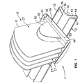
- FIG. 10 there is illustrated a slotted divider arrangement 10 according to the present invention.
- This arrangement 10 in the illustrated and preferred embodiment mounts on a support rail arrangement 11 which is positioned in close association with a worksurface 12.
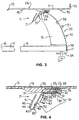
- the worksurface 12 as diagrammatically illustrated in Figure 3, has respective front and rear longitudinally extending edges 16 and 17, and defines thereon an enlarged and substantially horizontal upper surface 18.
- the worksurface 12 can be provided with legs (not shown) so as to function as the top of a table, or can be mounted on support arms which project outwardly from a wall positioned adjacent the rear edge of the worksurface, both such constructions being conventional and well known.
- the support rail arrangement 11 is intended for use in close association with the worksurface so as to provide additional mounting capability for office accessories or tools, such as the slotted divider arrangement 10.
- the support rail arrangement 11 includes an elongate support rail 21 which is preferably disposed so as to be adjacent and extend lengthwise along an edge of the worksurface 12, such as the rear edge 17 thereof.
- the support rail 21 is, in the illustrated arrangement, secured to an upper end of at least one, and typically a pair of, support arms or stanchions 22 which in the illustrated embodiment are secured to the worksurface and project upwardly therefrom adjacent the rear edge 17 so as to support the elongate support rail 21 in raised relationship relative to the worksurface.
- the slotted divider arrangement 10 includes a generally horizontal support base or tray 26 which can be removably but stably supported on top of the support rail 21, with the tray 26 and rail 21 being attached in a manner described hereinafter.
- the support tray 26 in turn removably mounts thereon one or more slotted divider elements 27 which can be positioned on top of the base tray 26 in side-by-side relation so as to define a plurality of adjacent upwardly-opening storage slots which also open forwardly of the worksurface.
- this rail is of a generally shallow and inverted V-shape configuration in cross section, and includes a rear leg 31 which is generally horizontal in the front-to-back direction of the worksurface.
- This rear leg 31 in turn is joined to a front leg 32 which, as it projects forwardly from its junction with the rear leg, is angled downwardly so that the legs 31 and 32 define a shallow V-like configuration.
- the rear leg 31 is defined by generally parallel and horizontal top and bottom walls 33 and 34, respectively, the latter being joined by a curved edge wall 35 at the rearward edges thereof.
- the walls 33 and 34 are vertically spaced so as to define a narrow slot 36 therebetween.
- This slot 36 extends lengthwise throughout the horizontal length of the rail and in addition opens horizontally forwardly so as to terminate at a mouth 37.
- the top wall 33, on the bottom surface thereof, is provided with a small downwardly projecting rib 38 which is disposed closely adjacent the closed end of the slot 36 for a purpose to be explained hereinafter.
- the front leg 32 of the support rail is of similar construction in that it is defined by spaced but substantially parallel top and bottom walls 41 and 42, respectfully, which are joined at their front edges by a curved edge wall 43. These walls thus define a slot 44 therebetween which also extends lengthwise throughout the rail, and opens generally rearwardly through the mouth 37.
- the slot 44 preferably extends at an angle relative to both the horizontal and vertical, whereas the slot 36 extends preferably horizontally.
- the top wall 41, on the inner surface thereof, is also preferably provided with a lengthwise-extending small rib 45 projecting downwardly therefrom in the vicinity of the closed end of the slot 44.
- the support rail 21 also has rib 46 extending lengthwise thereof along the undersurface of the rail substantially at the apex of the V as defined by the bottom walls 34 and 42.
- This rib 46 is of narrow width and projects outwardly only a limited extent, and at its outer end is joined to a lengthwise extending mounting rod 47 which is of increased cross-sectional size, and extends throughout substantially the length of the rail.
- the mounting rod 47 in the preferred embodiment is cylindrical in cross-section.
- the support rail 21, in the illustrated embodiment, is supported in upwardly spaced relation along the rear edge of the worksurface by at least one, and quite typically two or more, support arms or stanchions 22.
- This support arm 22 includes a main body or tower part 51 which is supported on the upper surface of the worksurface 11 adjacent the rear edge 17 thereof, and is cantilevered upwardly.
- This main body part 51 at its upper end terminates in front and rear support surfaces 52 and 53, respectively, which are angled with respect to one another so as to substantially supportingly bear directly under the rail bottom walls 42 and 34, respectively.
- the body part 51 also has a sleeve part 54 affixed thereto and extending transversely in generally horizontal and parallel relationship with the lengthwise extent of support rail 21.
- This sleeve part 54 has a cylindrical opening 55 extending horizontally and transversely through the body part 51 adjacent the upper end thereof.
- a narrow slot 56 opens upwardly from the opening 55 between the support surfaces 52 and 53, and extends transversely across the upper end of the body part 51.
- the opening 55 and slot 56 enable the mounting rod 47 and rib 46, respectively, as associated with the support rail 21 to be slidably inserted therein so as to secure the rail 21 and body part 51 together.
- the support arm 22 includes an L-shaped mounting part which has a generally upwardly extending leg 58 which overlaps and is fixedly secured to the rear upright surface of the body part 51. This, in the illustrated embodiment, is accomplished by means of a pair of pins 57 which project from the rear of the body part 51 and which are engaged within slots (not shown) formed in the upright leg 58 so as to permit fixed coupling of the leg 58 to the body part 51.
- This upright leg 58 is positioned so as to extend downwardly directly adjacent the worksurface rear edge 17 without protruding outwardly a significant extent, and the upright leg 58 at its lower end terminates in and is rigidly joined to a horizontally projecting forward leg 59, the latter being spaced downwardly from the bottom of the worksurface 12.
- This bottom horizontal leg 59 mounts thereon a manually adjustable fastening member 61.
- the latter is preferably threadedly engaged with the horizontal leg 59 and at its lower end has an enlarged head or knob which can be manually gripped, or gripped by a tool, so as to enable the upper end of the fastening member 61 to move into clamping engagement with the bottom of the worksurface upon rotation of the fastening member so as to secure the body part 51 tightly against the upper surface of the worksurface.
- the slotted divider arrangement 10 is defined primarily by an enlarged, planar, plate-like base wall 71 which extends in a generally horizontal plane when mounted on the support rail 21.
- the base wall 71 has a front edge 72 which is provided with a downwardly rounded or arcuate configuration both to improve the appearance thereof and to provide additional strength and stiffness.
- the rear edge of the base wall 71 has a flange 73 fixed thereto and projecting vertically upwardly therefrom through a small vertical extent, which flange also provides the base wall with increased strength and rigidity.
- This latter flange 73 also projects upwardly through a sufficient vertical extent so as to function as a rear stop or position limiting surface with respect to documents which are inserted into the slotted divider elements, as explained hereinafter.
- the base wall 71 has a plurality of small slots or openings 74 extending vertically therethrough.
- the slots 74 are disposed in uniformly spaced relationship within two rows which extend transversely across the width of the base wall, with one row being positioned more closely adjacent the front edge of the base wall, and the other row being positioned more closely adjacent the rear edge of the base wall.
- the rows of slots 74 are also spaced apart (i.e., in the front-to-back direction) by a distance which is greater than the front-to-back width of the support rail 21 so that the rows of slots are respectively positioned forwardly and rearwardly of the support rail.
- the tray 26 has a mounting flange 75 associated with the base wall 71 substantially centrally thereof.
- This flange 75 is offset horizontally downwardly from the base wall 71 by a small distance, and the flange 75 at one end (the forward end) is joined to the base wall 71 by a thickened reinforcing portion 76 which extends vertically therebetween.
- the other or rearward end of the flange 75, as well as the side edges of the flange, are free of direct connection to the base wall 71, whereby the mounting flange 75 is cantilevered rearwardly from the reinforcing portion 76 and thus functions similar to a stiff but resilient plate spring.
- the flange 75 adjacent the free end thereof, is provided with a pair of detent ribs or a detent recess on the upper surface so as to create a releasable detent-type engagement with the rail rib 38 when the support tray 26 is mounted on the support rail 21.
- the mounting flange 75 can be horizontally slidably inserted into the slot 36 associated with the rear rail leg 31 so that the base wall 71 of the tray 26 is securely and stably seated on the upper surface of the rail top wall 33 with this latter wall 33 being securely held between the base wall 71 and the mounting flange 75.
- the base tray is properly positioned and seated upon the support rail when the mounting flange 75 is fully inserted into the slot 36 so that the front edge of the top wall 33 substantially abuts the thickened portion 76 and at the same time the flange detents against the rail rib 38 so as to prevent accidental forward separation of the base tray from the support rail.
- the slotted divider element 27 when viewed in cross-section is of a generally upwardly-opening U-shape configuration and includes a main upright rear or support wall 81 which at its lower end is rigidly joined at a corner 91 to the rear of a base or bottom wall 82.
- This bottom wall 82 projects forwardly in substantially perpendicular relationship from the back wall 81 through a relatively small distance, and at its forward edge is joined through a corner 92 to a downwardly projecting front flange 83.
- the latter projects substantially perpendicularly downwardly from the bottom wall 82 so as to extend substantially in parallel relationship to the back wall 81.
- This front flange 83 is of short vertical extent and terminates in a lower free edge 84 which is adapted to bearingly engage the upper surface of the base tray 26 when the slotted divider element 27 is mounted thereon.
- the slotted divider element 27 also has a front wall 86 which projects upwardly from the corner 92 substantially coplanar with the front flange 83.
- This front wall 86 extends upwardly in sidewardly spaced but substantially parallel relationship with the back wall 81 and thus, in cooperation with the bottom wall 82, defines a channel-like storage slot 89 which opens upwardly and outwardly at both ends.
- the front wall 86 has a height which, as determined by the upper edge 87, is significantly less than, and in fact is typically about one-half the height of the back wall 81, the height of which is determined by its upper edge 87.
- the front wall 86 in the illustrated embodiment also has a generally rounded or arcuate peripheral edge so that it resembles approximately one-half of a cylinder or ellipse, and has a width (i.e., the length of the front wall in a direction transverse to the rail) which is significantly smaller than the width of the respective back wall 81, thereby providing improved aesthetics and accessibility with respect to at least the frontmost slotted divider element 27.
- the front flange 83 of the divider element has a pair of sidewardly-spaced tabs or hooks 85 cantilevered downwardly from the free edge 84, which tabs or hooks project downwardly through a transversely spaced pair of slots 74 formed in the base tray 26.
- the hooks 85 are preferably J- or L-shaped so that the lower horizontally projecting legs thereof project transversely under the base wall 71 to provide stability to the slotted divider elements by resisting tipping thereof.
- the slotted divider elements 27 can be individually positioned on the base tray 26 by orienting the divider elements so that the front and rear walls extend generally vertically to facilitate insertion of the J-hooks 85 through the slots 74 until the free edge of front flange 83 abuts the base wall 71. The slotted divider element is then vertically rotated through a small angle until the corner 91 abuts the top surface of the base wall 71, which in turn causes the J-hooks to engage under the base wall 71.
- a plurality of divider elements 27, up to four in the illustrated embodiment, can be sequentially mounted in side-by-side relationship on the base plate 26, which mounting starts from the rear and progressively works to the front. Further, due to the symmetry of the divider elements, they can be horizontally rotated 180° for mounting on the base plate so as to be inclined either rightwardly or leftwardly depending upon the preferred orientation of the worker.
- the slots 74 associated with the base plate are preferably spaced apart by a distance which substantially corresponds to the width of the divider elements when the latter are mounted on the base tray, whereby a plurality of divider slots 89 can thus be positioned in closely adjacent side-by-side relationship, substantially as illustrated by Figure 5.
- the plurality of storage slots 89 are readily accessible either from above or from the front of the worksurface, and thus various documents or objects can be conveniently stored within the storage slots 89.
- the rear flange 73 of the base plate 26 preferably projects upwardly a sufficient extent so as to project above the upper surfaces of the inclined bottom walls 82 of the divider elements 27, and thus functions as a stop surface for documents inserted into the storage slots.
- the front and back walls 81, 86 of the divider elements are disposed so as to extend at a small angle or incline relative to the vertical, and likewise the bottom wall 82 of the divider element also extends at a small incline relative to the horizontal, whereupon documents disposed in a respective storage slot will naturally lean against and be supported by the respective back wall 81.
- the slotted divider element 27 in its entirety, and the base tray 26 in its entirety, are each preferably formed from a generally thin sheet-like material so as to have a substantially uniform thickness throughout.
- both the slotted divider element 27 and the base tray 26 are each formed in one piece of a plastics material, such as ABS, PP, or HDPE, such as by injection molding. While the latter is preferred, it will be recognized that other forming and manufacturing techniques and materials can be utilized.
- the support rail 21 is preferably constructed of metal, such as aluminum, but other suitable materials can be utilized.
- the slotted divider arrangement can also be readily removed from the support rail, either partially or totally.
- the slotted divider elements 27 can be removed from the base tray 26 so that the latter remains on the support rail 21 and functions as a horizontal supporting tray or surface, as illustrated in Figure 2, or if desired the base tray 26 can also be readily removed from the support rail.
- the base tray 26 when mounted on the support rail 21, either with or without the slotted divider elements thereon, can also be slidably displaced longitudinally along the support rail so as to permit desired positioning thereof relative to the worksurface.
- the base tray 26 also includes pairs of feet 95 projecting downwardly from base wall 71 through a greater distance than the flange 75. These feet 95 enable the divider arrangement to be directly stably supported on the worksurface.
- support rail arrangement has been described above in conjunction with support stanchions which are secured to and project upwardly from the worksurface, it will be appreciated that the support rail can be supported independently of the worksurface, such as by means of arms which secure to an adjacent wall and project outwardly therefrom for securement to the support rail in the same manner as described herein, in which case the rail and its support would thus be free of any direct support or connection to the worksurface.
Landscapes
- Sheet Holders (AREA)
- Drawers Of Furniture (AREA)
Applications Claiming Priority (2)
| Application Number | Priority Date | Filing Date | Title |
|---|---|---|---|
| US09/304,161 US6227384B1 (en) | 1999-04-30 | 1999-04-30 | Slotted divider arrangement |
| US304161 | 1999-04-30 |
Publications (2)
| Publication Number | Publication Date |
|---|---|
| EP1048245A2 true EP1048245A2 (de) | 2000-11-02 |
| EP1048245A3 EP1048245A3 (de) | 2001-02-21 |
Family
ID=23175339
Family Applications (1)
| Application Number | Title | Priority Date | Filing Date |
|---|---|---|---|
| EP00108995A Withdrawn EP1048245A3 (de) | 1999-04-30 | 2000-04-27 | Geschlitzte Verteilanordnung |
Country Status (3)
| Country | Link |
|---|---|
| US (1) | US6227384B1 (de) |
| EP (1) | EP1048245A3 (de) |
| CA (1) | CA2306613A1 (de) |
Cited By (1)
| Publication number | Priority date | Publication date | Assignee | Title |
|---|---|---|---|---|
| EP1149544A3 (de) * | 2000-04-28 | 2002-03-13 | Haworth, Inc. | Mit Stützen auf einer Arbeitsplatte montierter abnehmbarer Lagerschrank |
Families Citing this family (38)
| Publication number | Priority date | Publication date | Assignee | Title |
|---|---|---|---|---|
| US6302366B1 (en) * | 1999-04-30 | 2001-10-16 | Haworth, Inc. | Grip clip |
| US6405878B1 (en) * | 2001-01-23 | 2002-06-18 | Norman G. Graham | Plate rail with easily removed arm |
| US6684929B2 (en) | 2002-02-15 | 2004-02-03 | Steelcase Development Corporation | Panel system |
| US6751914B2 (en) | 2002-03-01 | 2004-06-22 | Steelcase Development Corporation | Post and beam furniture system |
| USD478354S1 (en) | 2002-08-23 | 2003-08-12 | Officemate International Corp. | Incline paper sorter |
| USD502345S1 (en) * | 2002-09-25 | 2005-03-01 | Spectrum Concepts, Inc. | Media storage tray movable support |
| USD478355S1 (en) | 2002-10-24 | 2003-08-12 | Officemate International Corp. | Incline paper sorter |
| EP1413458A1 (de) * | 2002-10-25 | 2004-04-28 | Smead Manufacturing Company | Briefordner |
| USD489096S1 (en) | 2003-03-28 | 2004-04-27 | Officemate International Corp. | Paper sorter |
| US7152351B2 (en) * | 2003-07-24 | 2006-12-26 | Rubbermaid Incorporated | Cascadable file jackets |
| US20050016939A1 (en) * | 2003-07-24 | 2005-01-27 | Eby David C. | Desktop filing system |
| US7328799B2 (en) * | 2003-07-24 | 2008-02-12 | Rubbermaid Incorporated | Task trays |
| USD502220S1 (en) * | 2003-10-03 | 2005-02-22 | David M. Stravitz | Browser/sorter |
| US7086538B2 (en) * | 2003-11-04 | 2006-08-08 | Stravitz David M | Multi-section retaining/sorting/browsing apparatus |
| US20050173355A1 (en) * | 2003-11-04 | 2005-08-11 | Stravitz David M. | Multi-section retaining/sorting/browsing apparatus |
| US7389884B2 (en) * | 2003-11-04 | 2008-06-24 | Stravitz David M | Multi-section retaining/sorting/browsing apparatus |
| USD510600S1 (en) * | 2003-12-09 | 2005-10-11 | Smead Manufacturing Company | Letter file |
| USD502221S1 (en) * | 2004-01-08 | 2005-02-22 | Officemate International Corp. | Incline sorter |
| US7204373B2 (en) * | 2004-04-02 | 2007-04-17 | American Grease Stick Company | Angulated package and display system |
| US7918352B2 (en) * | 2004-04-02 | 2011-04-05 | Ags I-Prop, Llc | Angled package and display system |
| USD500803S1 (en) * | 2004-05-20 | 2005-01-11 | David M. Stravitz | Browser/sorter |
| USD504702S1 (en) * | 2004-09-23 | 2005-05-03 | David M. Stravitz | Browser/sorter |
| US9125833B2 (en) * | 2005-11-02 | 2015-09-08 | Relmada Therapeutics, Inc. | Multimodal abuse resistant and extended release opioid formulations |
| US8329744B2 (en) * | 2005-11-02 | 2012-12-11 | Relmada Therapeutics, Inc. | Methods of preventing the serotonin syndrome and compositions for use thereof |
| US20090082466A1 (en) * | 2006-01-27 | 2009-03-26 | Najib Babul | Abuse Resistant and Extended Release Formulations and Method of Use Thereof |
| WO2007056142A2 (en) * | 2005-11-02 | 2007-05-18 | Theraquest Biosciences, Llc | Methods of preventing the serotonin syndrome and compositions for use therefor |
| US8276523B2 (en) | 2008-05-28 | 2012-10-02 | Steelcase Inc. | Worksurface assembly |
| WO2010008863A1 (en) | 2008-06-23 | 2010-01-21 | Biodelivery Sciences International, Inc. | Multidirectional mucosal delivery devices and methods of use |
| USD678947S1 (en) * | 2012-03-06 | 2013-03-26 | Block And Company, Inc. | Sorter and writing implement holder |
| JP6340235B2 (ja) * | 2014-04-14 | 2018-06-06 | 株式会社吉川国工業所 | 靴収納用具 |
| CN104433305B (zh) * | 2014-11-24 | 2017-05-24 | 泉州百和仕展示用品有限公司 | 一种门店用自动吸附式宣传册叠放架 |
| US10010202B2 (en) * | 2015-05-07 | 2018-07-03 | Andrew Flocchini | Napkin holder |
| KR101694333B1 (ko) * | 2016-07-06 | 2017-01-17 | 주식회사 로이첸 | 의류 수납기구 |
| US11957258B2 (en) * | 2019-01-11 | 2024-04-16 | Peng-Yuan Chen | Top item holder |
| US10470573B1 (en) * | 2019-03-12 | 2019-11-12 | Sub-Zero, Inc. | Tray with support arm |
| USD1005092S1 (en) * | 2020-06-15 | 2023-11-21 | Hangzhou United Tools Co., Ltd. | Bracket |
| US11072198B1 (en) * | 2021-01-19 | 2021-07-27 | Vitalii Savryha | Modular paper organizer |
| US20260097608A1 (en) * | 2024-10-04 | 2026-04-09 | Askoh.Com Llc | Paper tray storage system |
Family Cites Families (42)
| Publication number | Priority date | Publication date | Assignee | Title |
|---|---|---|---|---|
| US401553A (en) | 1889-04-16 | Wood-working clamp | ||
| US1039554A (en) | 1912-05-23 | 1912-09-24 | Edward H B Lindhorst | Flag-holder for automobiles. |
| US1106265A (en) * | 1914-03-21 | 1914-08-04 | William Henry Whittle | File-box. |
| US1736574A (en) * | 1928-05-05 | 1929-11-19 | Binks Squire | Desk file |
| US2490269A (en) * | 1947-06-13 | 1949-12-06 | Johnson Edwin | Tray |
| US2551157A (en) | 1949-08-03 | 1951-05-01 | Price Brothers Inc | Sign bracket |
| US2658628A (en) * | 1950-07-07 | 1953-11-10 | Aurora Equipment Co | Adjustable shelf divider |
| US2751088A (en) * | 1952-05-07 | 1956-06-19 | Commercial Display Corp | Adjustable partition clip for trays and shelving |
| US2884139A (en) * | 1952-09-25 | 1959-04-28 | Aurora Equipment Co | Snap-on bin divider |
| US2759454A (en) * | 1953-06-01 | 1956-08-21 | Renska L Swart | Article holders |
| US2873860A (en) * | 1953-11-13 | 1959-02-17 | Florence J Holloway | Stationery rack |
| US2902166A (en) * | 1954-06-15 | 1959-09-01 | Morris W G Bahr | Storing and filing devices |
| US3812975A (en) * | 1971-12-27 | 1974-05-28 | J Gutierrez | Inter-actuating record holding structure |
| FR2271636B1 (de) * | 1974-01-25 | 1976-10-08 | Delage Jean | |
| US4034864A (en) * | 1975-02-03 | 1977-07-12 | Steelcase, Inc. | Document handling system |
| US4074810A (en) * | 1976-09-27 | 1978-02-21 | Rubbermaid Commercial Products Inc. | Combination tiered letter tray and vertical file |
| US4160570A (en) * | 1978-02-03 | 1979-07-10 | Aladdin Industries, Incorporated | Wall mounted modules for packaging, merchandising and storage |
| US4163497A (en) * | 1978-05-09 | 1979-08-07 | Mcewen William D | Pharmacist's prescription file holder |
| US4209098A (en) * | 1978-05-26 | 1980-06-24 | Adams John R | Adjustable storage system for fishing rods |
| US4323291A (en) | 1979-06-08 | 1982-04-06 | Hauserman Ltd. | Desk or the like with wire management |
| US4317416A (en) | 1979-12-17 | 1982-03-02 | Vanguard Diversified, Inc. | Connection means for assembling furniture |
| FR2544667B1 (fr) * | 1983-04-22 | 1986-02-07 | Services Equipements France | Casier oblique modulable |
| US4709891A (en) | 1986-01-02 | 1987-12-01 | Chicago Show Printing Co. | Support bracket for signs and advertising displays |
| US4762072A (en) * | 1986-10-07 | 1988-08-09 | Westinghouse Electric Corp. | Desk and space dividing wall panel assembly |
| US4905847A (en) * | 1987-02-02 | 1990-03-06 | Stuart Hall Company, Inc. | Display shelf system |
| US4852500A (en) | 1987-03-18 | 1989-08-01 | Herman Miller, Inc. | Integrated computer implement work area |
| DE3720639A1 (de) | 1987-06-23 | 1989-01-05 | Eggersmann Planmoebel | Buero-arbeitsplatz |
| FR2620317B1 (fr) * | 1987-09-10 | 1990-01-26 | Dacota Sa | Element de rangement pour documents ou autres et un ensemble de rangement a casiers inclines constitues de plusieurs desdits elements |
| US4884513A (en) | 1988-03-01 | 1989-12-05 | Herman Miller, Inc. | Work environment system |
| US4938442A (en) | 1988-06-21 | 1990-07-03 | Mastrodicasa Arthur R | Bracket and shelf assembly |
| DE8812473U1 (de) | 1988-10-03 | 1989-01-19 | VOKO - Franz Vogt & Co, 6301 Pohlheim | Arbeitsplatzvorrichtung |
| FR2642008B1 (fr) | 1989-01-26 | 1992-01-03 | Boitabloc | Support d'ecriture |
| US5103741A (en) | 1989-02-07 | 1992-04-14 | Steelcase Inc. | Modular furniture |
| US5092253A (en) * | 1989-02-07 | 1992-03-03 | Steelcase Inc. | Modular furniture |
| US4948205A (en) | 1989-03-08 | 1990-08-14 | Sligh Furniture Co. | Desk with concealed wire storage |
| DE3911017A1 (de) * | 1989-04-05 | 1990-10-11 | Ensslin Gmbh & Co | Labor- oder werkstattmoebel |
| US5048698A (en) | 1990-06-12 | 1991-09-17 | Westinghouse Electric Corp. | Office accessory mounting rail |
| US5057039A (en) | 1991-01-07 | 1991-10-15 | Westinghouse Electric Corp. | Electrical or communications monument for mounting along an edge of a work surface |
| USD333489S (en) | 1991-06-28 | 1993-02-23 | Steelcase Inc. | Diagonal paper sorter |
| US5486042A (en) | 1993-09-09 | 1996-01-23 | Steelcase, Inc. | Furniture arrangement |
| US5429252A (en) | 1993-11-02 | 1995-07-04 | Liu; Hung-Yang | Versatile rail for supporting objects in kitchen |
| US5955170A (en) * | 1995-09-11 | 1999-09-21 | Boone International, Inc. | Bulletin board mail holder and mail holder attaching mechanism |
-
1999
- 1999-04-30 US US09/304,161 patent/US6227384B1/en not_active Expired - Fee Related
-
2000
- 2000-04-26 CA CA002306613A patent/CA2306613A1/en not_active Abandoned
- 2000-04-27 EP EP00108995A patent/EP1048245A3/de not_active Withdrawn
Cited By (1)
| Publication number | Priority date | Publication date | Assignee | Title |
|---|---|---|---|---|
| EP1149544A3 (de) * | 2000-04-28 | 2002-03-13 | Haworth, Inc. | Mit Stützen auf einer Arbeitsplatte montierter abnehmbarer Lagerschrank |
Also Published As
| Publication number | Publication date |
|---|---|
| CA2306613A1 (en) | 2000-10-30 |
| US6227384B1 (en) | 2001-05-08 |
| EP1048245A3 (de) | 2001-02-21 |
Similar Documents
| Publication | Publication Date | Title |
|---|---|---|
| US6227384B1 (en) | Slotted divider arrangement | |
| US6267338B1 (en) | Support rail assembly for office accessories | |
| US6206206B1 (en) | Rail-mounted hanging file arrangement | |
| US6302366B1 (en) | Grip clip | |
| US9084482B2 (en) | Shelving systems and components therefor | |
| US20080136301A1 (en) | Tool and utensil stowage system | |
| US4316547A (en) | Hang rail support and hang rail | |
| EP0797401B1 (de) | Modulare aufbewahrungseinheit | |
| US6550875B1 (en) | Storage cabinet removably mounted on a worksurface by support stanchions | |
| US5779206A (en) | Hanger assembly | |
| US6481583B1 (en) | Tool holder system | |
| US8132679B2 (en) | Convertible card row | |
| US8910805B2 (en) | Shelving system and components | |
| US20100096349A1 (en) | Desktop organizer | |
| US20050092704A1 (en) | Storage organizers | |
| CA2367632C (en) | Funnel system for holding implements | |
| US5265358A (en) | Picture frame corner connector | |
| US6345722B1 (en) | Display rack for golf clubs | |
| US5191984A (en) | Display or storage rack for neckties and the like | |
| CA2257532A1 (en) | Rim top table | |
| US5417396A (en) | Universal upright interface bracket | |
| US3450304A (en) | Desk drawer construction | |
| JP3389874B2 (ja) | 部材の取付構造 | |
| US3842758A (en) | Over drawer head support | |
| US20080302739A1 (en) | Organizing and storing devices, systems, and methods |
Legal Events
| Date | Code | Title | Description |
|---|---|---|---|
| PUAI | Public reference made under article 153(3) epc to a published international application that has entered the european phase |
Free format text: ORIGINAL CODE: 0009012 |
|
| AK | Designated contracting states |
Kind code of ref document: A2 Designated state(s): AT BE CH CY DE DK ES FI FR GB GR IE IT LI LU MC NL PT SE |
|
| AX | Request for extension of the european patent |
Free format text: AL;LT;LV;MK;RO;SI |
|
| PUAL | Search report despatched |
Free format text: ORIGINAL CODE: 0009013 |
|
| AK | Designated contracting states |
Kind code of ref document: A3 Designated state(s): AT BE CH CY DE DK ES FI FR GB GR IE IT LI LU MC NL PT SE |
|
| AX | Request for extension of the european patent |
Free format text: AL;LT;LV;MK;RO;SI |
|
| 17P | Request for examination filed |
Effective date: 20010808 |
|
| AKX | Designation fees paid |
Free format text: AT BE CH CY DE DK ES FI FR GB GR IE IT LI LU MC NL PT SE |
|
| STAA | Information on the status of an ep patent application or granted ep patent |
Free format text: STATUS: THE APPLICATION HAS BEEN WITHDRAWN |
|
| 18W | Application withdrawn |
Withdrawal date: 20020617 |