EP1048247A1 - Ferrure d'articulation - Google Patents
Ferrure d'articulation Download PDFInfo
- Publication number
- EP1048247A1 EP1048247A1 EP00104060A EP00104060A EP1048247A1 EP 1048247 A1 EP1048247 A1 EP 1048247A1 EP 00104060 A EP00104060 A EP 00104060A EP 00104060 A EP00104060 A EP 00104060A EP 1048247 A1 EP1048247 A1 EP 1048247A1
- Authority
- EP
- European Patent Office
- Prior art keywords
- hinge
- stop plate
- fitting
- articulated
- area
- Prior art date
- Legal status (The legal status is an assumption and is not a legal conclusion. Google has not performed a legal analysis and makes no representation as to the accuracy of the status listed.)
- Withdrawn
Links
- 239000011324 bead Substances 0.000 claims abstract description 8
- 208000027418 Wounds and injury Diseases 0.000 description 4
- 230000006378 damage Effects 0.000 description 4
- 208000014674 injury Diseases 0.000 description 4
- 238000010276 construction Methods 0.000 description 3
- 230000001419 dependent effect Effects 0.000 description 1
- 239000000463 material Substances 0.000 description 1
- 230000001681 protective effect Effects 0.000 description 1
Images
Classifications
-
- A—HUMAN NECESSITIES
- A47—FURNITURE; DOMESTIC ARTICLES OR APPLIANCES; COFFEE MILLS; SPICE MILLS; SUCTION CLEANERS IN GENERAL
- A47C—CHAIRS; SOFAS; BEDS
- A47C20/00—Head-, foot- or like rests for beds, sofas or the like
- A47C20/04—Head-, foot- or like rests for beds, sofas or the like with adjustable inclination
-
- F—MECHANICAL ENGINEERING; LIGHTING; HEATING; WEAPONS; BLASTING
- F16—ENGINEERING ELEMENTS AND UNITS; GENERAL MEASURES FOR PRODUCING AND MAINTAINING EFFECTIVE FUNCTIONING OF MACHINES OR INSTALLATIONS; THERMAL INSULATION IN GENERAL
- F16C—SHAFTS; FLEXIBLE SHAFTS; ELEMENTS OR CRANKSHAFT MECHANISMS; ROTARY BODIES OTHER THAN GEARING ELEMENTS; BEARINGS
- F16C11/00—Pivots; Pivotal connections
- F16C11/04—Pivotal connections
Definitions
- the present invention relates to a hinge fitting with two by a hinge pin interconnected tabs, especially for use as Raised fitting for bed frames, slatted frames or the like, the maximum possible swivel angle of the two brackets - starting from an extended position - is mechanically limited.
- the possible maximum swivel angle is related to the stretched position, almost 90 °.
- Such a large maximum swivel angle is undesirable in many cases, especially when using one Articulated fitting as a stand-up fitting for lying frames, slatted frames or the like.
- the present invention has for its object a hinge fitting Generic type to create in a simple manner Swing angle limit reached and at the same time the risk of injury Squeezes in the joint area is eliminated.
- this object is achieved according to the invention by that to limit the swivel angle at least on one side of the mounting bracket a covering the joint area and connected to both tabs Stop plate is provided, each at a predetermined distance from Hinge axis and through both the stop plate and the respective bracket passing connecting bolt is connected to the tabs and that the Provide the stop plate with elongated holes in the passage area of the connecting bolts is.
- a second solution to the object of the invention is that for Swivel angle limitation at least on one side of the joint fitting the stop plate covering the joint area and connected to both brackets is provided, each at a predetermined distance from the hinge axis and by one that passes through both the stop plate and the respective tab Connecting bolt is connected to the tabs and that the tabs are provided with elongated holes in the passage area of the hinge pin.
- the maximum swivel angle is achieved by the stop plate in both cases of the two tabs limited relative to each other, whereby in the case of the first Proposed solution, this limitation primarily through the elongated holes in the stop plate and with the second proposed solution through the elongated holes in the tabs is achieved in the area of the hinge pin.
- the one-sided cover is used to protect against the risk of injury of the joint fitting in the immediate joint area should be sufficient easily but also possible, such a cover plate on both sides of the To attach hinge fitting.
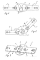
- FIG. 1-4 is an inventive and overall with the reference numeral 1 designated hinge fitting shown, which consists essentially of two articulated interconnected tabs 2 and 3, a hinge pin 4, a stop plate 5 and two connecting bolts 6, by means of which the stop plate 5 is connected to the tabs 2 and 3.
- the one designated by reference number 2 is Provide a bracket 7 in the area of the hinge pin 4, the dimension of this offset 7 being approximately the material thickness of the tabs 2 or 3 corresponds, so that the non-cranked tab 3 in one plane with the non-cranked Area of the tab 2 is.
- the stop plate 5 is through the mentioned Connecting bolts 6, for example in the form of rivet bolts or screws, connected to the two tabs 2 and 3.
- the stop plate 5 is in the passage area the connecting bolt 6 equipped with elongated holes 8.
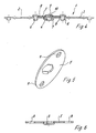
- Figures 4-6 also show very clearly that the stop plate 5 in the middle, in the assembled state lying in the joint area with a bead-like Characteristic 9 is provided, the depth of which is at least the thickness of the latter Area lying head 10 of the hinge pin 4 corresponds.
- This head 10 of the hinge pin 4 can thus be in the pronounced area of the Bead 9 move freely.
- the elongated holes 8 of the stop plate 5 are structurally chosen so that pivoting of the two tabs 2 and 3 against each other from that shown in Figure 1 Stretch position only up to a predetermined and desired angular amount is possible.
- the connecting bolts 6 are located on the circumference at the mutually facing ends of the two elongated holes 8, whereas the connecting bolts 6 when the joint fitting is in the extended position oblong holes 8 are at a maximum distance from the opposite ends, as clearly shown in Figure 4.
- the length of the elongated holes 8 can thus be used to influence the maximum possible swivel angle between the two brackets 2 and 3.
- the head 10 of the hinge pin 4 Moved relative to each other during the pivoting of the two tabs 2 and 3 the head 10 of the hinge pin 4 within the shape of the bead 9, so that if necessary, the length of the bead 9 is used to limit the swivel angle could be.
- the elongated holes 8 could be larger than in FIG. 4 shown because the swivel angle limitation by striking the head 10th of the hinge pin 4 would take place at the front ends 11 of the bead 9.
- a stop plate 5 is provided on one side of the hinge fitting. Deviating from this, it is also conceivable a corresponding, additional stop plate 5 on the opposite Attach side, so that the joint area is covered on both sides to protect.
- hinge fittings of the type previously used, so that If necessary, appropriate hinge fittings can also be retrofitted with a swivel angle limitation can be equipped in the sense explained above.
- the connecting bolts 6 for connecting the stop plate 5 to the tabs 2 and 3 can consist of rivet bolts as well as bolts.
- the stop plate 5 can instead of the shown and described expression also be provided exclusively with an elongated hole.
Landscapes
- Engineering & Computer Science (AREA)
- General Engineering & Computer Science (AREA)
- Mechanical Engineering (AREA)
- Health & Medical Sciences (AREA)
- General Health & Medical Sciences (AREA)
- Nursing (AREA)
- Hinges (AREA)
Applications Claiming Priority (2)
| Application Number | Priority Date | Filing Date | Title |
|---|---|---|---|
| DE29907520U DE29907520U1 (de) | 1999-04-28 | 1999-04-28 | Gelenkbeschlag |
| DE29907520U | 1999-04-28 |
Publications (1)
| Publication Number | Publication Date |
|---|---|
| EP1048247A1 true EP1048247A1 (fr) | 2000-11-02 |
Family
ID=8072817
Family Applications (1)
| Application Number | Title | Priority Date | Filing Date |
|---|---|---|---|
| EP00104060A Withdrawn EP1048247A1 (fr) | 1999-04-28 | 2000-02-28 | Ferrure d'articulation |
Country Status (2)
| Country | Link |
|---|---|
| EP (1) | EP1048247A1 (fr) |
| DE (1) | DE29907520U1 (fr) |
Cited By (1)
| Publication number | Priority date | Publication date | Assignee | Title |
|---|---|---|---|---|
| WO2013104115A1 (fr) * | 2012-01-11 | 2013-07-18 | Lu Wei | Régulateur de charnière |
Families Citing this family (3)
| Publication number | Priority date | Publication date | Assignee | Title |
|---|---|---|---|---|
| DE102010017174C5 (de) * | 2010-05-31 | 2023-06-29 | Hettich Franke Gmbh & Co. Kg | Gelenk und klappbares Möbelteil |
| DE102021113881A1 (de) | 2021-05-28 | 2022-12-01 | Malu Gmbh | Klappbeschlag zur schwenkbaren Verbindung zweier Möbelteile |
| DE102021113882B3 (de) | 2021-05-28 | 2022-09-22 | Malu Gmbh | Klappbeschlag zur schwenkbaren Verbindung zweier Möbelteile |
Citations (2)
| Publication number | Priority date | Publication date | Assignee | Title |
|---|---|---|---|---|
| FR2705021A1 (fr) * | 1993-05-11 | 1994-11-18 | Sichelschmidt Stanzwerk | Dispositif pour déplacer une partie supérieure fixée de manière articulée à un cadre de sommier. |
| EP0703336A1 (fr) * | 1994-09-13 | 1996-03-27 | Liebherr-Hausgeräte Gmbh | Liaison articulée entre une porte et une partie d'un corps, notamment pour un réfrigérateur et/ou congélateur |
-
1999
- 1999-04-28 DE DE29907520U patent/DE29907520U1/de not_active Expired - Lifetime
-
2000
- 2000-02-28 EP EP00104060A patent/EP1048247A1/fr not_active Withdrawn
Patent Citations (2)
| Publication number | Priority date | Publication date | Assignee | Title |
|---|---|---|---|---|
| FR2705021A1 (fr) * | 1993-05-11 | 1994-11-18 | Sichelschmidt Stanzwerk | Dispositif pour déplacer une partie supérieure fixée de manière articulée à un cadre de sommier. |
| EP0703336A1 (fr) * | 1994-09-13 | 1996-03-27 | Liebherr-Hausgeräte Gmbh | Liaison articulée entre une porte et une partie d'un corps, notamment pour un réfrigérateur et/ou congélateur |
Cited By (1)
| Publication number | Priority date | Publication date | Assignee | Title |
|---|---|---|---|---|
| WO2013104115A1 (fr) * | 2012-01-11 | 2013-07-18 | Lu Wei | Régulateur de charnière |
Also Published As
| Publication number | Publication date |
|---|---|
| DE29907520U1 (de) | 1999-09-09 |
Similar Documents
| Publication | Publication Date | Title |
|---|---|---|
| DE4219681C2 (de) | Einstellbares Abhebescharnier | |
| EP1238179B1 (fr) | Composant dote d'une penture et destine a des portes, des fenetres ou equivalent | |
| DE4337082A1 (de) | Fahrzeugkarosserie | |
| DE3626451C2 (fr) | ||
| AT403717B (de) | Scharnier mit quetschschutzvorrichtung | |
| EP0478639A1 (fr) | Charniere. | |
| EP1048247A1 (fr) | Ferrure d'articulation | |
| DE3813088C2 (fr) | ||
| WO1991008658A1 (fr) | Cadre pour une armoire de commande ou similaire | |
| DE60010806T2 (de) | Verdeckter Öffnungsbeschlag für Drehflügeltür oder -Fenster | |
| DE2211523A1 (de) | Schliesstueck fuer metall- oder kunststoff-fenster oder -tueren | |
| DE2900632A1 (de) | Schlosseinheit | |
| DE19832123C1 (de) | Hinterschweißtasche zum Befestigen von Scharnierlappen an einem Zargenprofilabschnitt | |
| DE2423436A1 (de) | Scharnier | |
| DE2131852C3 (de) | Klappenscharnier | |
| DE10244048B4 (de) | Vorrichtung zum Ausrichten einer Fahrzeugtür, insbesondere einer Kraftfahrzeugtür | |
| DE3120065A1 (de) | Moebelscharnier | |
| EP1516763B1 (fr) | Structure de caisse | |
| DE19618912A1 (de) | Lamelle für ein Blatt eines vorzugsweise auf und ab bewegbaren Rollverschlusses für ein Tor, eine Tür, ein Fenster o. dgl. Öffnung | |
| EP0671531B1 (fr) | Charnière | |
| EP0976594A1 (fr) | Porte de chargement | |
| EP1422371A2 (fr) | Charnière pour portes, fenêtres ou similaires | |
| DE19823411C1 (de) | Richtbeschlag, insbesondere für Holztüren oder- fenster | |
| DE4323939A1 (de) | Gelenkvorrichtung, insbesondere für Drehkipptür oder -fenster | |
| DE1784136C3 (de) | Eckumlenkung für Treibstangenbeschläge von Fenstern, Türen o.dgl |
Legal Events
| Date | Code | Title | Description |
|---|---|---|---|
| PUAI | Public reference made under article 153(3) epc to a published international application that has entered the european phase |
Free format text: ORIGINAL CODE: 0009012 |
|
| AK | Designated contracting states |
Kind code of ref document: A1 Designated state(s): CH DE ES FR LI |
|
| AX | Request for extension of the european patent |
Free format text: AL;LT;LV;MK;RO;SI |
|
| 17P | Request for examination filed |
Effective date: 20010420 |
|
| AKX | Designation fees paid |
Free format text: CH DE ES FR LI |
|
| STAA | Information on the status of an ep patent application or granted ep patent |
Free format text: STATUS: THE APPLICATION IS DEEMED TO BE WITHDRAWN |
|
| 18D | Application deemed to be withdrawn |
Effective date: 20020903 |