EP1048260A2 - Appareil de nettoyage par le vide muni d'un haut pouvoir filtrant - Google Patents
Appareil de nettoyage par le vide muni d'un haut pouvoir filtrant Download PDFInfo
- Publication number
- EP1048260A2 EP1048260A2 EP00201418A EP00201418A EP1048260A2 EP 1048260 A2 EP1048260 A2 EP 1048260A2 EP 00201418 A EP00201418 A EP 00201418A EP 00201418 A EP00201418 A EP 00201418A EP 1048260 A2 EP1048260 A2 EP 1048260A2
- Authority
- EP
- European Patent Office
- Prior art keywords
- cleaning apparatus
- vacuum cleaning
- fact
- tray
- filtering power
- Prior art date
- Legal status (The legal status is an assumption and is not a legal conclusion. Google has not performed a legal analysis and makes no representation as to the accuracy of the status listed.)
- Withdrawn
Links
Images


Classifications
-
- A—HUMAN NECESSITIES
- A47—FURNITURE; DOMESTIC ARTICLES OR APPLIANCES; COFFEE MILLS; SPICE MILLS; SUCTION CLEANERS IN GENERAL
- A47L—DOMESTIC WASHING OR CLEANING; SUCTION CLEANERS IN GENERAL
- A47L9/00—Details or accessories of suction cleaners, e.g. mechanical means for controlling the suction or for effecting pulsating action; Storing devices specially adapted to suction cleaners or parts thereof; Carrying-vehicles specially adapted for suction cleaners
- A47L9/10—Filters; Dust separators; Dust removal; Automatic exchange of filters
- A47L9/18—Liquid filters
- A47L9/181—Separating by passing the air through a liquid bath
-
- A—HUMAN NECESSITIES
- A47—FURNITURE; DOMESTIC ARTICLES OR APPLIANCES; COFFEE MILLS; SPICE MILLS; SUCTION CLEANERS IN GENERAL
- A47L—DOMESTIC WASHING OR CLEANING; SUCTION CLEANERS IN GENERAL
- A47L9/00—Details or accessories of suction cleaners, e.g. mechanical means for controlling the suction or for effecting pulsating action; Storing devices specially adapted to suction cleaners or parts thereof; Carrying-vehicles specially adapted for suction cleaners
- A47L9/10—Filters; Dust separators; Dust removal; Automatic exchange of filters
- A47L9/18—Liquid filters
- A47L9/185—Means for the mechanical control of flow of air, e.g. deflectors, baffles or labyrinths
Definitions
- the present invention relates to a vacuum cleaning apparatus with high filtering power.
- the recent vacuum cleaning apparatus both for household and industrial use are generally provided with a plurality of filters to ensure good quality of air coming out from the apparatus.
- the vacuum cleaners of the state of the art generally are provided with one or more filters even of a different kind, arranged in cascade upstream of the sucking motor and another filter downstream of said motor.
- These filters may be carried out in various ways by means of layers of dense non woven fibers, layers of materials with suitable antistatic features, active coal and so forth.
- air is purified by several passes, while the dust particles are collected in filters or suitable interchangeable bags.
- the conventional vacuum cleaners cannot achieve e perfectly clean air because number and quality of the filters to be used, very often are not suitable to capture the particles of very little diameter.
- Vacuum cleaners using also water as a working fluid do not succeed to be substantially better than the above mentioned simpler and cheaper types, because water is simply mixed with air so that it cannot be an efficient filter for the dust particles present in the environment.
- the object of the present invention is to overcome the drawbacks afflicting the mentioned prior art devices.
- Object of the invention is therefore to provide a vacuum cleaning apparatus with high filtering power, easy to be manufactured, very efficient in collecting even the finest dust particles, of reliable operation, simple maintenance and with low production costs.
- a vacuum cleaning apparatus with high filtering power comprises an outer housing operatively connected to air sucking, filtering and conveying means wherein said housing is provided with a water reservoir operatively associated with said sucked air conveying means and baffle means opposing air passage so as to obtain a complete nebulization of at least a portion of water into the sucked air, before the so obtained flow passes through said filtering means.
- the vacuum cleaning apparatus with high filtering power according to the invention is characterized by the features recited in Claim 1.
- the vacuum cleaning apparatus is comprised of several parts with improved maintenance because said outer housing has a transparent envelope connected to a head, where said envelope has a partially crowned frustum-conical base adapted to be joined to a mobile support plate and a cylindrical body having also the function of water reservoir, while the head comprises said sucking means and part of the air filtering means.
- a tray is arranged, consisting of two circle portions arranged on different planes and connected by a vertical portion, said tray being provided with said baffle means on the lower surface of the portion with greater area, said baffle means comprising a frustum-conical surface concentric with an injector connected to said transparent envelope and leading to a retaining surface.
- the filtering operation of the filters is made lighter as a decanter is arranged above the tray, having a complementary shape with said tray, and with further passage means such as a hole connected with the tray, lateral walls with cylindrical development for deposit of impurities and mechanical means for connection with said head.
- the vacuum cleaning apparatus of the invention has a very noiseless operation as said envelope is provided with a sucked air inlet consisting of a plurality of layers of sound absorbing material.
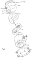
- the vacuum cleaning apparatus 1 with high filtering power comprises an outer housing preferably formed by an envelope 2 made of transparent plastic material and a head 12.
- the envelope 2 has a frustum-conical base 16 which is crowned for a portion of its lateral surface and is connected to a mobile support plate 17 by screws or equivalent mechanical fastening means.
- the body of the envelope 2 is cylindrical and on its lateral surface is provided with an inlet 3 to which a corrugated sucking tube 18 is externally connected, at the free end of which the conventional fittings of a vacuum cleaner are connected (not shown on the drawings).
- the inlet 3 is silenced as it is made of two blocks of sound absorbing material.
- the inlet is also connected inside the cylindrical body of the envelope 2 to a descending diagonal duct 4, whose lower end is directed upwards after a U bend.
- the duct 4 is associated with a support ring 5 which is fixed to the base 16 by screws or equivalent mechanical fastening means.
- the support ring 5 holds a cylinder or injector 6 in a position concentric with the lower opening of the duct 4.
- the cylinder or injector 6 has the function of conveying upwards a mixture consisting of water present inside the envelope 2 and sucked air, as it will be better explained hereinafter.
- a tray 7 is arranged, with a diameter slightly less than the diameter of the envelope but with its surface offset on two different planes connected by a vertical portion.
- the surface comprises two portions of a circle, the one with a larger area and the other with a smaller area, where the portion of larger area is arranged in the lower position and after the tray 7 has been placed over the envelope 2, has a lower frustum-conical surface 9 concentric with the injector 6 and ending with a retaining surface 8.
- the portion of smaller area has a through hole in which a filter 10 is arranged, holding a first part of the sucked impurities, when the nebulized water passes through the sucked air, as described hereinafter.
- Such decanter has lateral walls with cylindrical development for collecting the very fine particles as it will be described hereinafter.
- the head 12 On the decanter the head 12 is arranged, comprising a motor 14 of known type supporting a microfilter 13 with filtering power, an extremely fine outlet filter 15 to ensure a perfect purification of air coming out from the present apparatus, the electric supply and the control panel.
- the head 12 is fixedly connected to the decanter 11 by a screw or equivalent mechanical fastening means and is then fixed to the transparent envelope 2 by means of known hooks not shown in the drawings.
- the motor generates inside the apparatus 1 such a vacuum as to allow suction of air by the corrugated tube 18 at its free end not shown in the drawings. Sucked air then passes through the inlet 3 and the duct 4, reaching the partially flooded injector 6.
- microfilter 13 will withhold other impurities while air will subsequently flow through filter 15 for a further purification.
- vacuum cleaning apparatus of the present invention is not only environmentally friendly for its operation features but also versatile, because it allows use of many accessories known in this field, such as those ejecting water before suction but it is also possible its use as simple air purification device.
Landscapes
- Engineering & Computer Science (AREA)
- Mechanical Engineering (AREA)
- Cleaning In General (AREA)
- Filters For Electric Vacuum Cleaners (AREA)
- Filtration Of Liquid (AREA)
Applications Claiming Priority (2)
| Application Number | Priority Date | Filing Date | Title |
|---|---|---|---|
| ITMI990854 IT1312211B1 (it) | 1999-04-23 | 1999-04-23 | Apparecchio aspirapolvere ad elevato potere filtrante |
| ITMI990854 | 1999-04-23 |
Publications (2)
| Publication Number | Publication Date |
|---|---|
| EP1048260A2 true EP1048260A2 (fr) | 2000-11-02 |
| EP1048260A3 EP1048260A3 (fr) | 2001-01-24 |
Family
ID=11382800
Family Applications (1)
| Application Number | Title | Priority Date | Filing Date |
|---|---|---|---|
| EP00201418A Withdrawn EP1048260A3 (fr) | 1999-04-23 | 2000-04-19 | Appareil de nettoyage par le vide muni d'un haut pouvoir filtrant |
Country Status (2)
| Country | Link |
|---|---|
| EP (1) | EP1048260A3 (fr) |
| IT (1) | IT1312211B1 (fr) |
Cited By (2)
| Publication number | Priority date | Publication date | Assignee | Title |
|---|---|---|---|---|
| WO2004062455A1 (fr) * | 2003-01-16 | 2004-07-29 | Vaso Gluhajic | Filtre a liquide par ejection gravitationnelle |
| WO2010005334A1 (fr) * | 2008-05-27 | 2010-01-14 | Vaso Gluhajic | Filtre humide president et son application |
Family Cites Families (6)
| Publication number | Priority date | Publication date | Assignee | Title |
|---|---|---|---|---|
| US1363859A (en) * | 1920-01-15 | 1920-12-28 | Fetters Norman Craig | Vacuum-cleaner |
| GB249875A (en) * | 1925-03-26 | 1926-10-21 | Siemens Schuckertwerke Gmbh | Improvements in or relating to dust aspirators |
| US2539867A (en) * | 1948-07-02 | 1951-01-30 | William H Schnabel | Vacuum cleaner cartridge |
| US2954095A (en) * | 1957-09-30 | 1960-09-27 | Rexair Inc | Vacuum cleaner |
| WO1991010392A1 (fr) * | 1990-01-17 | 1991-07-25 | Hans Zengerer | Aspirateur |
| NO971571L (no) * | 1997-04-04 | 1998-10-05 | Kkelien Ingar B | Dobbeltvirkende selvroterende skrÕstilt vannfilter |
-
1999
- 1999-04-23 IT ITMI990854 patent/IT1312211B1/it active
-
2000
- 2000-04-19 EP EP00201418A patent/EP1048260A3/fr not_active Withdrawn
Cited By (2)
| Publication number | Priority date | Publication date | Assignee | Title |
|---|---|---|---|---|
| WO2004062455A1 (fr) * | 2003-01-16 | 2004-07-29 | Vaso Gluhajic | Filtre a liquide par ejection gravitationnelle |
| WO2010005334A1 (fr) * | 2008-05-27 | 2010-01-14 | Vaso Gluhajic | Filtre humide president et son application |
Also Published As
| Publication number | Publication date |
|---|---|
| ITMI990854A1 (it) | 2000-10-23 |
| EP1048260A3 (fr) | 2001-01-24 |
| IT1312211B1 (it) | 2002-04-09 |
Similar Documents
| Publication | Publication Date | Title |
|---|---|---|
| CA2538717C (fr) | Depoussiereur puissant pour aspirateur | |
| CA2535388C (fr) | Dispositif de depoussierage de la sous-section d'un aspirateur | |
| RU2198581C2 (ru) | Пылесос с тангенциальным отделением мусора | |
| CA2447976A1 (fr) | Collecteur de poussiere pour aspirateur a cyclone | |
| WO2008011797A1 (fr) | Vide-poussière secondaire à séparation cyclonique pour aspirateur | |
| EP1023864A3 (fr) | Dispositif pour collecter la poussière destiné à un aspirateur et aspirateur du type balai | |
| EP1915940A1 (fr) | Dispositif de depoussierage d un appareil de nettoyage de type parallele | |
| JP2011110234A (ja) | サイクロン式集塵装置およびこれを備えた電気掃除機 | |
| US6055701A (en) | Liquid pick-up appliances for use in surface cleaning or drying | |
| CN109893034B (zh) | 回收桶及其清洁设备 | |
| KR20070078679A (ko) | 집진장치 | |
| CN113854911B (zh) | 一种箱体及具有其的清洁设备 | |
| CN111346433A (zh) | 移动式焊接烟尘净化器及净化方法 | |
| CN110893081A (zh) | 一种吸尘器组件及随手吸 | |
| CN112890665B (zh) | 一种垃圾分离器及一种清洁设备 | |
| CN100374065C (zh) | 外置式吸尘器除尘装置 | |
| EP1048260A2 (fr) | Appareil de nettoyage par le vide muni d'un haut pouvoir filtrant | |
| CN213696722U (zh) | 一种双腔式尘气分离装置及具有其的除螨仪 | |
| CN110840331A (zh) | 一种尘气分离装置及吸尘器 | |
| EP1707098B1 (fr) | Aspirateur à bain de liquide avec un déflecteur incliné | |
| CN209984149U (zh) | 垃圾箱及扫地机器人 | |
| CN215820806U (zh) | 一种用于洗地机的污水箱及洗地机 | |
| CN108714002A (zh) | 一种吸尘器及其尘杯组件 | |
| CN101897559A (zh) | 一种真空吸尘器集尘桶的固定结构 | |
| CN101889843A (zh) | 灰尘分离及自清洁式集尘桶 |
Legal Events
| Date | Code | Title | Description |
|---|---|---|---|
| PUAI | Public reference made under article 153(3) epc to a published international application that has entered the european phase |
Free format text: ORIGINAL CODE: 0009012 |
|
| AK | Designated contracting states |
Kind code of ref document: A2 Designated state(s): AT BE CH CY DE DK ES FI FR GB GR IE IT LI LU MC NL PT SE |
|
| AX | Request for extension of the european patent |
Free format text: AL;LT;LV;MK;RO;SI |
|
| PUAL | Search report despatched |
Free format text: ORIGINAL CODE: 0009013 |
|
| AK | Designated contracting states |
Kind code of ref document: A3 Designated state(s): AT BE CH CY DE DK ES FI FR GB GR IE IT LI LU MC NL PT SE |
|
| AX | Request for extension of the european patent |
Free format text: AL;LT;LV;MK;RO;SI |
|
| 17P | Request for examination filed |
Effective date: 20010616 |
|
| AKX | Designation fees paid |
Free format text: AT BE CH CY DE DK ES FI FR GB GR IE IT LI LU MC NL PT SE |
|
| 17Q | First examination report despatched |
Effective date: 20050414 |
|
| STAA | Information on the status of an ep patent application or granted ep patent |
Free format text: STATUS: THE APPLICATION IS DEEMED TO BE WITHDRAWN |
|
| 18D | Application deemed to be withdrawn |
Effective date: 20050825 |