EP1048311A2 - Dispositif d'injection à aiguille muni d'ailettes - Google Patents
Dispositif d'injection à aiguille muni d'ailettes Download PDFInfo
- Publication number
- EP1048311A2 EP1048311A2 EP00108789A EP00108789A EP1048311A2 EP 1048311 A2 EP1048311 A2 EP 1048311A2 EP 00108789 A EP00108789 A EP 00108789A EP 00108789 A EP00108789 A EP 00108789A EP 1048311 A2 EP1048311 A2 EP 1048311A2
- Authority
- EP
- European Patent Office
- Prior art keywords
- injection needle
- protector
- connector
- stretchable member
- holder
- Prior art date
- Legal status (The legal status is an assumption and is not a legal conclusion. Google has not performed a legal analysis and makes no representation as to the accuracy of the status listed.)
- Granted
Links
Images


Classifications
-
- A—HUMAN NECESSITIES
- A61—MEDICAL OR VETERINARY SCIENCE; HYGIENE
- A61M—DEVICES FOR INTRODUCING MEDIA INTO, OR ONTO, THE BODY; DEVICES FOR TRANSDUCING BODY MEDIA OR FOR TAKING MEDIA FROM THE BODY; DEVICES FOR PRODUCING OR ENDING SLEEP OR STUPOR
- A61M25/00—Catheters; Hollow probes
- A61M25/01—Introducing, guiding, advancing, emplacing or holding catheters
- A61M25/06—Body-piercing guide needles or the like
- A61M25/0612—Devices for protecting the needle; Devices to help insertion of the needle, e.g. wings or holders
- A61M25/0637—Butterfly or winged devices, e.g. for facilitating handling or for attachment to the skin
-
- A—HUMAN NECESSITIES
- A61—MEDICAL OR VETERINARY SCIENCE; HYGIENE
- A61M—DEVICES FOR INTRODUCING MEDIA INTO, OR ONTO, THE BODY; DEVICES FOR TRANSDUCING BODY MEDIA OR FOR TAKING MEDIA FROM THE BODY; DEVICES FOR PRODUCING OR ENDING SLEEP OR STUPOR
- A61M25/00—Catheters; Hollow probes
- A61M25/01—Introducing, guiding, advancing, emplacing or holding catheters
- A61M25/06—Body-piercing guide needles or the like
- A61M25/0612—Devices for protecting the needle; Devices to help insertion of the needle, e.g. wings or holders
- A61M25/0618—Devices for protecting the needle; Devices to help insertion of the needle, e.g. wings or holders having means for protecting only the distal tip of the needle, e.g. a needle guard
- A61M25/0625—Devices for protecting the needle; Devices to help insertion of the needle, e.g. wings or holders having means for protecting only the distal tip of the needle, e.g. a needle guard with a permanent connection to the needle hub, e.g. a guiding rail, a locking mechanism or a guard advancement mechanism
-
- A—HUMAN NECESSITIES
- A61—MEDICAL OR VETERINARY SCIENCE; HYGIENE
- A61M—DEVICES FOR INTRODUCING MEDIA INTO, OR ONTO, THE BODY; DEVICES FOR TRANSDUCING BODY MEDIA OR FOR TAKING MEDIA FROM THE BODY; DEVICES FOR PRODUCING OR ENDING SLEEP OR STUPOR
- A61M5/00—Devices for bringing media into the body in a subcutaneous, intra-vascular or intramuscular way; Accessories therefor, e.g. filling or cleaning devices, arm-rests
- A61M5/178—Syringes
- A61M5/31—Details
- A61M5/32—Needles; Details of needles pertaining to their connection with syringe or hub; Accessories for bringing the needle into, or holding the needle on, the body; Devices for protection of needles
- A61M5/3205—Apparatus for removing or disposing of used needles or syringes, e.g. containers; Means for protection against accidental injuries from used needles
- A61M5/321—Means for protection against accidental injuries by used needles
- A61M5/3243—Means for protection against accidental injuries by used needles being axially-extensible, e.g. protective sleeves coaxially slidable on the syringe barrel
- A61M5/3245—Constructional features thereof, e.g. to improve manipulation or functioning
- A61M2005/3247—Means to impede repositioning of protection sleeve from needle covering to needle uncovering position
- A61M2005/325—Means obstructing the needle passage at distal end of a needle protection sleeve
-
- A—HUMAN NECESSITIES
- A61—MEDICAL OR VETERINARY SCIENCE; HYGIENE
- A61M—DEVICES FOR INTRODUCING MEDIA INTO, OR ONTO, THE BODY; DEVICES FOR TRANSDUCING BODY MEDIA OR FOR TAKING MEDIA FROM THE BODY; DEVICES FOR PRODUCING OR ENDING SLEEP OR STUPOR
- A61M5/00—Devices for bringing media into the body in a subcutaneous, intra-vascular or intramuscular way; Accessories therefor, e.g. filling or cleaning devices, arm-rests
- A61M5/178—Syringes
- A61M5/31—Details
- A61M5/32—Needles; Details of needles pertaining to their connection with syringe or hub; Accessories for bringing the needle into, or holding the needle on, the body; Devices for protection of needles
- A61M5/3205—Apparatus for removing or disposing of used needles or syringes, e.g. containers; Means for protection against accidental injuries from used needles
- A61M5/321—Means for protection against accidental injuries by used needles
- A61M5/3243—Means for protection against accidental injuries by used needles being axially-extensible, e.g. protective sleeves coaxially slidable on the syringe barrel
-
- A—HUMAN NECESSITIES
- A61—MEDICAL OR VETERINARY SCIENCE; HYGIENE
- A61M—DEVICES FOR INTRODUCING MEDIA INTO, OR ONTO, THE BODY; DEVICES FOR TRANSDUCING BODY MEDIA OR FOR TAKING MEDIA FROM THE BODY; DEVICES FOR PRODUCING OR ENDING SLEEP OR STUPOR
- A61M5/00—Devices for bringing media into the body in a subcutaneous, intra-vascular or intramuscular way; Accessories therefor, e.g. filling or cleaning devices, arm-rests
- A61M5/46—Devices for bringing media into the body in a subcutaneous, intra-vascular or intramuscular way; Accessories therefor, e.g. filling or cleaning devices, arm-rests having means for controlling depth of insertion
Definitions
- the present invention relates to a winged injection needle device having a cover for containing an injection needle after use.
- the present invention is directed to a covering means for a winged injection needle that frequently is used in a procedure such as a liquid infusion, a blood transfusion, extracorporeal blood circulation, or the like.
- a winged injection needle device includes an injection needle, a needle base for fixing the injection needle, and a tube connected to the needle base. Most of the means for preventing sticking accidents are formed so that the injection needle and the needle base can move relative to each other in order to prevent sticking accidents after use. Conventional means roughly can be classified into two types: a device having a wing attached to an injection needle or a needle base; and a device having a wing attached to a cover.
- the injection needle of the present invention belongs to the latter type.
- injection needle is disclosed in, for example, USP No. 5,549,571 A.
- a wing is attached to a hub in which an injection needle penetrates, and the hub is connected to the needle base via a stretchable connection part. Therefore, by stretching or contracting the connection part, it is possible to cover the injection needle by the hub or expose the needle.
- the object of the present invention is to provide a winged injection needle device satisfying the following three conditions: (1) it is possible to contain a used injection needle safely and easily; (2) a structure is simple and the manufacturing cost is low, and (3) a used injection needle device can be disposed of sanitarily.
- the winged injection needle device of the present invention includes an injection needle; a holder holding the base end of the injection needle and having a through hole in communication with the injection needle; a tube through which a liquid medicine can flow; a connector connecting the holder and the tube so that they are in communication with each other; a cylindrical stretchable member capable of stretching or contracting in an axial direction, one end of the member being connected to at least one of the holder, the tube and the connector; and a cylindrical protector through which the injection needle passes, the protector being provided with a wing and being connected to another end of the stretchable member.
- the stretchable member is stretched or contracted so as to slide the protector to change its position with respect to the injection needle within a range including the position in which the tip of the injection needle is completely contained in the protector, whereby an exposed length of the injection needle exposed from the protector can be changed into a desired length, and the stretchable member itself can maintain a certain stretched or contracted state.
- the exposed length of the injection needle can be changed freely and its state can be maintained. Therefore, users do not have to select injection needles having a different length depending upon injection sites or other factors. Thus, the injection needle device can been used extremely easily.
- the stretchable member has an accordion structure. With such a configuration, functions required for the stretchable member can be attained easily.
- the stretchable member is made of polyolefine.
- the stretchable member has an accordion-structured part and has a stretching ratio, which is a ratio of the length of the accordion-structured part stretched to the maximum with respect to the length of the accordion-structured part contracted to the minimum, in the range from 2.5 to 3.6.
- a stretching ratio which is a ratio of the length of the accordion-structured part stretched to the maximum with respect to the length of the accordion-structured part contracted to the minimum, in the range from 2.5 to 3.6.
- a difference between the stretched length and the contracted length of the stretchable member is larger than the maximum exposed length of the injection needle.
- the wing is rotatably attached to a cylindrical part of the protector.
- a cavity diameter at the tip of the protector is 1.1 to 2.0 times the diameter of the injection needle.
- the tip of the protector is provided with a means for preventing the re-protrusion of the injection needle contained in a cavity of the protector.
- the connector has a first part and a second part
- the tube is fitted onto the outer surface of the second part
- the holder is directly or indirectly connected to a cavity of the first part of the connector
- the stretchable member is fitted onto the outer surface of the first part of the connector.
- a winged injection needle device includes an injection needle; a holder holding the base end of the injection needle and having a through hole being in communication with the injection needle, an anchoring member provided on the holder; a tube in which a liquid medicine can flow; a connector having an engaging part capable of engaging the anchoring member provided on the holder and connected to the tube, a cylindrical stretchable member capable of stretching or contracting in an axial direction, one end of the member being coupled to at least one of the tube and the connector; and a cylindrical protector provided with a wing through which the injection needle passes and coupled to another end of the stretchable member.
- the stretchable member is stretched or contracted so as to slide the protector to change its position with respect to the injection needle within a range including the position in which the tip of the injection needle is completely contained in the protector, whereby an exposed length of the injection needle exposed from the protector can be changed into a desired length.
- the holder and the connector are not connected to each other in an initial state, and they are irreversibly connected to each other by contracting the stretchable member so as to engage the anchoring member of the holder with the engaging part of the connector.
- the connector is a hollow cylinder and has a catch on the inner surface
- the anchoring member includes a pair of elastic legs and each of the tips of the elastic legs is provided with an engaging latch, and the inner diameter of the connector is larger than the external size of the tip of the engaging part and smaller than the external size of the engaging latch.
- the winged injection needle of the present invention it is possible to prevent sticking accidents by being unintentionally stuck by an injection needle after a user finished a procedure on a patient. Consequently, it is possible to avoid the infection or contamination caused by sticking accidents. Furthermore, since the cover containing the injection needle can be disposed of sanitarily, the contamination and/or infection of persons other than the users can be prevented.
- the winged injection needle device of the present invention has a simple structure and can be manufactured at low cost, and therefore it can be widely used for medical instruments.
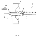
- the schematic structure of a winged injection needle device according to the first embodiment of the present invention will be described with reference to FIG. 1.
- the winged injection needle device 1 of the present invention has a liquid medicine passageway including an injection needle 2, a cylindrical holder 3 tightly fixing the injection needle 2, a tube 4 of polyvinyl chloride resin, for example, through which a liquid medicine can flow, and a cylindrical connector 5 connecting the holder 3 and the tube 4.
- the injection needle device further includes a cylindrical stretchable member 6 made of polyethylene and having an accordion structure, and a protector 8 having a pair of wings 7 at both sides.
- Members constituting the above-mentioned liquid medicine passageway extend through the cavity of the stretchable member 6 and the protector 8.
- the holder 3 is fitted into a through hole of the connector 5, and the tube 4 is fitted onto the outside of the connector 5.
- One end of the stretchable member 6 is fitted onto the outside of the end of tube 4 that is fitted onto the connector 5.
- Another end of the stretchable member 6 is fitted onto the protector base end 9 of the protector 8.
- the holder 3 and the connector 5 may be formed as one unit. In such a case, one end of the stretchable member 6 may be fitted onto any one of the tube 4, the holder 3, and the connector 5.
- the stretchable member 6 is tightly fixed to the connection part of the protector base end 9 and to the end of the tube 4 (or the connector 5) so as not to be easily detached when the stretchable member 6 is stretched.
- the protector tip 10 of the protector 8 has a pore 11.
- the injection needle 2 penetrating through the cavity of the protector 8 can be exposed from the pore 11 or retracted into the protector 8.
- the protector tip 10 is tapered off so that the injection needle does not move when the needle is stuck into the patient's body.
- the diameter of the pore 11 is of a size larger than that of the injection needle.
- a needle cap 14 is placed on the tip of the injection needle 2.
- the cylindrical stretchable member 6 is made, for example, of polyethylene and is capable of stretching or contracting in an axial direction by its accordion structure.
- the stretch or contraction of the stretchable member 6 permits the protector 8 to slide on the outside of the injection needle 2.
- the injection needle 2 can be covered with and contained in the protector 8 or can be exposed from the protector 8.
- the accordion structure is formed so that it can maintain a stretched or contracted state after the external force applied to the accordion structure is removed (free state). Therefore, the stretchable member 6 can maintain the desired length of the stretchable state within the stretchable range.
- the length of the injection needle 2 exposed from the protector 8 (hereinafter, an "exposed length" will be referred to) optionally can be adjusted within the predetermined range.
- the exposed length of the injection needle 2 can be changed optionally, users do not have to select injection needles having a different length depending upon the injection sites or other factors, thus facilitating the procedure with the injection needle device.
- this device makes it possible to finely adjust the exposed length, which cannot be attained by using the standard length of the needle. Therefore, this device is useful in clinical treatment in which various cases are required to be treated.
- a well-known toggle structure such as that of a stretchable straw may be used. Therefore, the details are not described herein.
- the protector can contain the injection needle 2 completely when the stretchable member 6 is stretched to the maximum.
- the stretch-contract difference is larger than the maximum exposed length of the injection needle.
- the maximum exposed length of the injection needle substantially is determined depending upon the applications of use. Consequently, the practically necessary stretch-contract difference also is determined.
- the stretch-contract difference is effected by the length of the part of the stretchable member 6 capable of stretching or contracting, and therefore the length of the stretchable member 6 is also determined.
- a material for the stretchable member 6 is not particularly limited and any materials can be used as long as they are capable of plastically stretching or contracting and capable of maintaining the stretched state.
- a material used for a drinking straw, etc. can be used.
- a preferable example of the material for the stretchable member 6 includes polyolefin such as polyethylene, polypropylene, etc., polyvinyl chloride resin, and the like.
- a material for the protector is not particularly limited and any materials can be used, for example materials used for a needle base and a wing of a conventional winged injection needle device.
- the protector 8 and the wing 7 may be made of different members, respectively. Occasionally, it is rather desirable that the protector 8 and the wing 7 are made of different members in terms of the application or function.
- the wing 7 generally requires a flexibility so as to easily follow the skin, while the protector 8 requires the hardness so as to hold and contain the injection needle 2.
- the wing 7 and the protector 8 are separately formed and the wing 7 is rotatably attached around the protector 8, a user conveniently can select the direction of the injection needle when sticking the needle into a patient body.
- the diameter of the pore 11 of the protector tip 10 is 1.1 to 2.0 times the diameter of the injection needle 2. It is sufficient that the cavity of the protector tip 10 has a diameter such that the injection needle 2 can smoothly penetrate through the cavity; When the diameter is too large, the needle tip cannot be well maintained at the time of sticking. On the contrary, when the diameter is too small, it is difficult for the injection needle to freely slide when the injection needle is covered and contained.
- a method for using the winged injection needle device of this embodiment will be briefly explained.
- the needle cap 14 is removed; then the injection needle 2 is stuck into a patient's body while holding the wing 7 so as to administer the liquid solution into the patient body after sticking; thereafter (after the injection procedure), the winged injection needle device 1 is retracted from the patient's body; and the stretchable member 6 is drawn by holding both the base end of the tube 4 or the stretchable member 6 and the protector 8 so that the stretchable member 6 is stretched .
- the exposed injection needle 2 can be contained in the cavity of the protector 8. In this state, the winged injection needle device 1 as a whole is disposed of. Since the injection needle 2 is covered, the risk of sticking accidents in the disposal process, etc. is reduced.
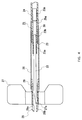
- Fig. 2 is a schematic cross-sectional view showing a winged injection needle device according to a second embodiment of the present invention.
- Fig. 3 is an exploded cross-sectional view showing the device of Fig. 2.
- the injection needle 22 is held in a through hole of a cylindrical holder 23.
- the holder 23 includes a small-diameter part 23a positioned at the side of the injection needle 22 and a large-diameter part 23b positioned at the rear part of the small-diameter part 23a.
- the injection needle 22 is fitted into the small-diameter part 23a so as to be held.
- One end of a connecting pipe 30 is fitted into the large-diameter part 23b.
- Another end of the connecting pipe 30 is fitted into a first part 25a of a cylindrical connector 25. Therefore, the holder 23 and the connector 25 are connected to each other via the connecting pipe 30.
- a tube 24 is fitted onto the second part 25b of the connector 25.
- the first part 25a has a diameter larger that that of the second part. However, it is not necessary that the diameters are in such relation, provided that the injection needle 22 can be held by and the tube 24 is fitted onto the respective part of the connector 25.
- the members from the tube 24 to the injection needle 22 form one through hole.
- Reference numeral 28 denotes a cylindrical protector and it can slide on the outer surface of the injection needle 22.
- a wing 27 is attached to the protector 28 at a hub 27a that is positioned at the center of the wing 27 and can rotate around the outer surface of the protector 28.
- An outer surface step 28a provided at the outer surface of the protector 28 prevents the wing 27 from moving in the direction toward the injection needle 22.
- a wing stopper 29 provided at the rear part of the protector 28 prevents the wing 27 from moving in the direction toward the base end of the injection needle 22.
- Reference numeral 26 denotes a stretchable member. One end of the stretchable member 26 is fitted onto the outside of the wing stopper 29 to be secured, and another end is fitted onto the first part 25a of the connector 25 to be secured. Materials etc. of the stretchable member 26 are as the same as those of the first embodiment shown in FIG. 1.
- stretch or contraction of the stretchable member 26 permits the protector 28 to slide on the outside of the injection needle 22.
- the injection needle 22 can be covered with and contained in the protector 28 or can be exposed from the protector 28.
- the accordion structure is formed so that it can maintain a stretched or contracted state after the external force applied to the accordion structure is removed (free state). Therefore, the stretchable member 26 can maintain the desired length of the stretched state within the stretchable range.
- the length of the injection needle 22 exposed from the protector 28 optionally can be adjusted within the predetermined range.
- a stretching ratio which is a ratio of a length of the accordion-structured part stretched to the maximum with respect to the length thereof contracted to the minimum, is set to be in the range from 2.5 to 3.6.
- the range of the stretching ratio is determined as follows.
- the stretching ratio of the accordion structure is determined in accordance with a wall thickness of materials and the pitch of accordion folds.
- the wall thickness of the material used such kind of the accordion structure is generally in the range from 0.18 to 0.25 mm. Too small a wall thickness does not provide a sufficient strength. Too large a wall thickness makes it difficult to increase the stretching ratio. Therefore, the practical range of the wall thickness used for the injection needle device of the present invention should be further limited than the above-mentioned range. Thus in the practical range, the wall thickness is sufficiently small that it does not affect the stretching ratio and the stretching ratio is determined in accordance with only the pitch of the accordion folds.
- the force required for stretch or contraction depends on the pitch of accordion folds
- the force is substantially determined in accordance with the stretching ratio. That is, the larger the stretching ratio is, the larger the force required for stretch or contraction is.
- the characteristics required for the accordion-structured part used for the injection needle device of the present invention are such that a force required for stretch or contraction is appropriate, and the stretching ratio is sufficiently large, in addition to an appropriate strength.
- the stretching ratio should be 2.5 or more.
- Too large a stretching ratio means too large a force is required for stretch or contraction. Such a too large required force causes difficulty in stretching or contracting the accordion-structured part when the injection needle is in the patient's body. Furthermore, if the stretching ratio, i.e., the pitch is increased, the difference between the inner diameter and the outer diameter of the accordion-structured part in its contracted condition is increased. Since it is difficult to reduce the inner diameter because of the size of the contained member, the outer diameter has to be increased to obtain the increased stretching ratio. Thus the increased stretching ratio makes the size of the injection needle device large. Therefore, the practical upper limit of the stretching ratio should be 3.6.
- the appropriate stretching ratio is set to be in the range from 2.5 to 3.6 from the viewpoint of the conditions required for the injection needle device and the practical selecting range of the wall thickness and the pitch.
- the inner diameter of the protector 28 is small at the tip and slightly larger at the rear part.
- the protector 28 is provided with an inner surface step 28b.
- the diameter of the small-diameter part is the same as that of the pore 11 of the protector tip 10 in the first embodiment.
- Fig. 4 shows a state in which the injection needle 22 is contained in the protector 28 by stretching the stretchable member 26 in the injection needle device having the above-mentioned configuration.
- the injection needle 22 does not easily protrude from the protector 28. That is, the tip of the injection needle 22 is brought into contact with the inner surface step 28b of the protector 28, thereby being prevented from protruding.
- the winged injection needle device it is made to be extremely easy to manufacture the winged injection needle device, because of the rational structure of connecting each member.
- the feature of the structure is that the tube 24 is fitted onto the small-diameter part 25b of the connector 25; the holder 23 is connected to the large diameter part 25a of the connector 25 via the connecting pipe 30; and the stretchable member 26 is fitted onto the outer surface of the large-diameter part 25a of the connector 25.
- the stretchable member 26 can be connected reliably to the base end of the injection needle 22.
- the winged injection needle device of the third embodiment according to the present invention will be described with reference to Fig. 5.
- the same elements as those of Fig. 1 are given to the same numbers and the explanations are not repeated herein.
- the holder 53 to which the injection needle 2 is fixed is detachably held in the cavity of the protector 58.
- An anchoring member 52 including a pair of elastic legs is attached to the rear end of the holder 53.
- Anchoring latches 52a are respectively formed on the elastic legs of the anchoring member 52.
- Anchoring catches 55a are formed on the inner surface of the cylindrical connector 55 attached to the tube 4.
- the external size 56 of the anchoring latches 52a of the anchoring member 52 is larger than the inner diameter of the connector 55.
- the anchoring member 52 is anchored to the connector 55. Consequently, the injection needle 2 is coupled to the connector 55. Furthermore, since the external size of the tip of the elastic legs of the anchoring member 52 is smaller than the inner diameter of the connector 55, the anchoring member 52 easily can be inserted into the connector 55.
- the connector 55 is not connected to the holder 53 in the initial state.
- the connector 55 is connected to the holder 53 by moving the anchoring member 52 with holding the protector 58 so as to anchor to the connector 55.
- the force of holding the anchoring member 52 to the connector 55 is larger than the force of holding the holder 53 in the cavity of the protector 58. Therefore, when the holder 53 is connected to the connector 55, by stretching the stretchable member 6 while holding the protector 58, the holder 53 is detached from the cavity of the protector 58 while the connection between the holder 53 and the connector 55 is maintained.
- a method for using the winged injection needle device of this embodiment will be briefly explained.
- the holder 53 is detachably fitted into the cavity of the protector 58.
- the stretchable member 6 is contracted thus to bring the holder 53 closer to the connector 55 so as to fit the anchoring member 52 into the cavity of the connector 55.
- the tube 4 is drawn in the direction in which the tube is taken apart from the protector 58, the holder 53 that was non-securably fitted into the protector 58 is detached from the protector 58 while the holder 53 is connected to the connector 55 as the stretchable member 6 is stretched.
- the injection needle 2 is covered with and contained in the protector 58.
- Fig. 6 is a schematic cross-sectional view showing a winged injection needle device according to a fourth embodiment of the present invention.
- the same elements as those of Fig. 1 are given to the same numbers and the explanations are not repeated herein.
- a slit 17 is formed on the tip of the protector 8.
- Reference numeral 18 denotes a protrusion prevention stopper, which is movably attached so that it can pass through the slit 17 and be inserted into the cavity of the protector 8.
- the protrusion prevention stopper 18 is inserted into the cavity of the protector 8, thereby preventing the injection needle 2 from protruding.
- the slit 17 may be replaced by a hole.
- the stopper 18 may be provided in a package together with the injection needle, to be attached to the device if necessary, instead of attaching the stopper 18 to the protector from the beginning.
Landscapes
- Health & Medical Sciences (AREA)
- Life Sciences & Earth Sciences (AREA)
- Biophysics (AREA)
- Pulmonology (AREA)
- Engineering & Computer Science (AREA)
- Anesthesiology (AREA)
- Biomedical Technology (AREA)
- Heart & Thoracic Surgery (AREA)
- Hematology (AREA)
- Animal Behavior & Ethology (AREA)
- General Health & Medical Sciences (AREA)
- Public Health (AREA)
- Veterinary Medicine (AREA)
- Infusion, Injection, And Reservoir Apparatuses (AREA)
Applications Claiming Priority (4)
| Application Number | Priority Date | Filing Date | Title |
|---|---|---|---|
| JP11868399 | 1999-04-26 | ||
| JP11868399 | 1999-04-26 | ||
| JP25575599A JP4348578B2 (ja) | 1999-04-26 | 1999-09-09 | 翼付き注射針装置 |
| JP25575599 | 1999-09-09 |
Publications (3)
| Publication Number | Publication Date |
|---|---|
| EP1048311A2 true EP1048311A2 (fr) | 2000-11-02 |
| EP1048311A3 EP1048311A3 (fr) | 2002-09-04 |
| EP1048311B1 EP1048311B1 (fr) | 2005-07-06 |
Family
ID=26456578
Family Applications (1)
| Application Number | Title | Priority Date | Filing Date |
|---|---|---|---|
| EP00108789A Expired - Lifetime EP1048311B1 (fr) | 1999-04-26 | 2000-04-25 | Dispositif d'injection à aiguille muni d'ailettes |
Country Status (5)
| Country | Link |
|---|---|
| US (1) | US6375640B1 (fr) |
| EP (1) | EP1048311B1 (fr) |
| JP (1) | JP4348578B2 (fr) |
| CN (1) | CN1262317C (fr) |
| DE (1) | DE60021144T2 (fr) |
Cited By (5)
| Publication number | Priority date | Publication date | Assignee | Title |
|---|---|---|---|---|
| WO2003026725A1 (fr) * | 2001-09-20 | 2003-04-03 | Kabushiki Kaisha Top | Aiguille de retenue a ailettes |
| FR2852850A1 (fr) * | 2003-03-28 | 2004-10-01 | Perouse Laboratoires | Dispositif d'injection |
| WO2015042161A1 (fr) * | 2013-09-18 | 2015-03-26 | David Stroup | Dispositif de perfusion médicale et procédés d'utilisation |
| EP2952221A4 (fr) * | 2013-01-30 | 2016-11-02 | Equipos Médicos Vizcarra S A | Cathéter intraveineux périphérique fermé à système de sécurité civpcss |
| US10549028B2 (en) | 2013-09-18 | 2020-02-04 | Alliance Vascular Devices, Llc | Medical infusion device and methods of use |
Families Citing this family (77)
| Publication number | Priority date | Publication date | Assignee | Title |
|---|---|---|---|---|
| US6855130B2 (en) * | 2000-03-07 | 2005-02-15 | Becton, Dickinson And Company | Passive safety device for needle of IV infusion or blood collection set |
| US6832992B2 (en) * | 2000-03-07 | 2004-12-21 | Becton, Dickinson And Company | Passive safety device for needle of blood collection set |
| US6537259B1 (en) | 2000-03-07 | 2003-03-25 | Becton, Dickinson And Company | Passive safety device |
| US6474523B2 (en) * | 2001-01-08 | 2002-11-05 | Trg Accessories Llc | Piece of baggage having an adjustable strap for alternatively supporting the piece of baggage from one's waist or shoulder |
| US6984223B2 (en) | 2001-11-13 | 2006-01-10 | Becton, Dickinson And Company | Needle safety device |
| JP4151311B2 (ja) * | 2002-05-24 | 2008-09-17 | ニプロ株式会社 | 留置針 |
| JP4648615B2 (ja) * | 2003-04-04 | 2011-03-09 | 株式会社ジェイ・エム・エス | 翼付きシールドを有する医療用針装置 |
| US6840920B2 (en) * | 2003-05-09 | 2005-01-11 | Visual Connections | Butterfly needle with passive guard |
| CN100502967C (zh) * | 2003-08-13 | 2009-06-24 | 杨章民 | 注射器的针头结构 |
| US7425208B1 (en) | 2003-08-29 | 2008-09-16 | Vitello Jonathan J | Needle assembly facilitating complete removal or nearly complete removal of a composition from a container |
| US20060229573A1 (en) * | 2005-04-08 | 2006-10-12 | Mckinley Medical L.L.L.P. | Adjustable infusion catheter |
| US20080097405A1 (en) * | 2006-07-28 | 2008-04-24 | Miller Stephen C | Luer fitting for power injectable PICC |
| US20080154212A1 (en) * | 2006-12-26 | 2008-06-26 | Stat Medical Devices, Inc. | Syringe with retractable needle support |
| US8323251B2 (en) | 2008-01-14 | 2012-12-04 | Fenwal, Inc. | Phlebotomy needle assembly and frangible cover |
| US20090198214A1 (en) * | 2008-02-01 | 2009-08-06 | Istvan Bognar | Butterfly Needle Devices and Methods Relating Thereto |
| EP2110149B1 (fr) * | 2008-03-28 | 2017-05-03 | Fenwal, Inc. | Assemblage d'aiguille à ailettes et couvercle fragile |
| JP2010214096A (ja) * | 2009-02-19 | 2010-09-30 | Jms Co Ltd | 医療用針装置 |
| US9480799B2 (en) * | 2009-04-08 | 2016-11-01 | Stat Medical Devices, Inc. | Retractable needle assembly utilizing a standard interface and syringe utilizing the same |
| US20110125130A1 (en) * | 2009-04-08 | 2011-05-26 | Stat Medical Devices, Inc. | Retractable needle assembly and syringe utilizing the same |
| US8986249B2 (en) * | 2009-04-08 | 2015-03-24 | Stat Medical Devices, Inc. | Retractable needle assembly and syringe utilizing the same |
| US9044552B2 (en) * | 2009-04-08 | 2015-06-02 | Stat Medical Devices, Inc. | Needle safety system and method |
| US9408984B2 (en) | 2009-09-15 | 2016-08-09 | Becton, Dickinson And Company | Self-injection device |
| US8597229B2 (en) * | 2009-12-24 | 2013-12-03 | Vr Medical Technology, Llc | Automated peritoneal dialysis cycler and methods of use |
| US9402967B1 (en) | 2010-05-27 | 2016-08-02 | Medical Device Engineering, Llc | Tamper evident cap assembly |
| CN102078651A (zh) * | 2010-09-30 | 2011-06-01 | 山东中保康医疗器具有限公司 | 带有紧固式接头的输液器 |
| US8864708B1 (en) | 2010-12-03 | 2014-10-21 | Medical Device Engineering, LLC. | Tamper indicating closure assembly |
| US9311592B1 (en) | 2012-08-31 | 2016-04-12 | Medical Device Engineering, LLC. | Support and closure assembly for discharge port of a syringe and tracking system therefore |
| US9078981B2 (en) * | 2012-09-21 | 2015-07-14 | Boston Scientific Scimed Inc. | Catheter system including an embolism protection device |
| US10524710B2 (en) | 2012-11-15 | 2020-01-07 | Becton, Dickinson And Company | Passive double drive member activated safety blood collection device |
| US20150360005A1 (en) * | 2013-01-30 | 2015-12-17 | Equipos Médicos Vizcarra, S.A. | Peripheral intravenous catheter with bellows-type passive safety system ivcbts |
| US9821152B1 (en) | 2013-03-04 | 2017-11-21 | Medical Device Engineering, LLC. | Closure assembly |
| US9861784B2 (en) | 2013-12-03 | 2018-01-09 | Becton, Dickinson And Company | Blood collection device with double pivot shields |
| US9855191B1 (en) | 2013-12-09 | 2018-01-02 | Jonathan J. Vitello | Tamper evident shield assembly with tracking |
| US10912898B1 (en) | 2014-02-03 | 2021-02-09 | Medical Device Engineering Llc | Tamper evident cap for medical fitting |
| US10207099B1 (en) | 2014-02-21 | 2019-02-19 | Patrick Vitello | Closure assembly for medical fitting |
| US10166347B1 (en) | 2014-07-18 | 2019-01-01 | Patrick Vitello | Closure assembly for a medical device |
| US10300263B1 (en) | 2015-02-27 | 2019-05-28 | Timothy Brandon Hunt | Closure assembly for a medical connector |
| US10166343B1 (en) | 2015-03-13 | 2019-01-01 | Timothy Brandon Hunt | Noise evident tamper cap |
| US10315024B1 (en) | 2015-03-19 | 2019-06-11 | Patick Vitello | Torque limiting closure assembly |
| KR101589006B1 (ko) * | 2015-10-17 | 2016-02-12 | 주식회사 메덱셀 | 펜니들에 대한 안전보호시스템 |
| CN105854131B (zh) * | 2016-03-07 | 2018-12-18 | 西安交通大学第一附属医院 | 一种注射器针头保护装置 |
| US11097071B1 (en) | 2016-12-14 | 2021-08-24 | International Medical Industries Inc. | Tamper evident assembly |
| US10307548B1 (en) | 2016-12-14 | 2019-06-04 | Timothy Brandon Hunt | Tracking system and method for medical devices |
| US10953162B1 (en) | 2016-12-28 | 2021-03-23 | Timothy Brandon Hunt | Tamper evident closure assembly |
| WO2018160401A1 (fr) * | 2017-02-28 | 2018-09-07 | Boston Scientific Scimed, Inc. | Aiguilles articulées |
| US10758684B1 (en) | 2017-03-03 | 2020-09-01 | Jonathan J. Vitello | Tamper evident assembly |
| US11040149B1 (en) | 2017-03-30 | 2021-06-22 | International Medical Industries | Tamper evident closure assembly for a medical device |
| US10888672B1 (en) | 2017-04-06 | 2021-01-12 | International Medical Industries, Inc. | Tamper evident closure assembly for a medical device |
| US10933202B1 (en) | 2017-05-19 | 2021-03-02 | International Medical Industries Inc. | Indicator member of low strength resistance for a tamper evident closure |
| US10898659B1 (en) | 2017-05-19 | 2021-01-26 | International Medical Industries Inc. | System for handling and dispensing a plurality of products |
| CN107497018B (zh) * | 2017-09-29 | 2019-12-24 | 郑州大学第一附属医院 | 一次性小儿用安全注射针 |
| US11541180B1 (en) | 2017-12-21 | 2023-01-03 | Patrick Vitello | Closure assembly having a snap-fit construction |
| US11278681B1 (en) | 2018-02-20 | 2022-03-22 | Robert Banik | Tamper evident adaptor closure |
| US11413406B1 (en) | 2018-03-05 | 2022-08-16 | Jonathan J. Vitello | Tamper evident assembly |
| CN108354635B (zh) * | 2018-03-06 | 2024-05-31 | 万军 | 一种可伸缩天线式肿瘤穿刺活检针 |
| US11793987B1 (en) | 2018-07-02 | 2023-10-24 | Patrick Vitello | Flex tec closure assembly for a medical dispenser |
| US11779520B1 (en) | 2018-07-02 | 2023-10-10 | Patrick Vitello | Closure for a medical dispenser including a one-piece tip cap |
| US11857751B1 (en) | 2018-07-02 | 2024-01-02 | International Medical Industries Inc. | Assembly for a medical connector |
| US11690994B1 (en) | 2018-07-13 | 2023-07-04 | Robert Banik | Modular medical connector |
| US11426328B1 (en) | 2018-08-31 | 2022-08-30 | Alexander Ollmann | Closure for a medical container |
| US11471610B1 (en) | 2018-10-18 | 2022-10-18 | Robert Banik | Asymmetrical closure for a medical device |
| USD948713S1 (en) | 2019-09-03 | 2022-04-12 | International Medical Industries, Inc. | Asymmetrical self righting tip cap |
| USD903865S1 (en) | 2018-11-19 | 2020-12-01 | International Medical Industries, Inc. | Self-righting tip cap |
| US11911339B1 (en) | 2019-08-15 | 2024-02-27 | Peter Lehel | Universal additive port cap |
| US11697527B1 (en) | 2019-09-11 | 2023-07-11 | Logan Hendren | Tamper evident closure assembly |
| CN110801570A (zh) * | 2019-11-12 | 2020-02-18 | 江苏诺尔贝斯医疗科技有限公司 | 一种医用导管 |
| US11357588B1 (en) | 2019-11-25 | 2022-06-14 | Patrick Vitello | Needle packaging and disposal assembly |
| CN110747105A (zh) * | 2019-11-28 | 2020-02-04 | 北京擎科生物科技有限公司 | 一种共通道打液装置 |
| TWI720808B (zh) * | 2020-02-05 | 2021-03-01 | 善德生化科技股份有限公司 | 翼型針具之保護套 |
| US11904149B1 (en) | 2020-02-18 | 2024-02-20 | Jonathan Vitello | Oral tamper evident closure with retained indicator |
| CN111743549B (zh) * | 2020-07-03 | 2021-02-19 | 于美瑛 | 一种血液科抽血器 |
| US11523970B1 (en) | 2020-08-28 | 2022-12-13 | Jonathan Vitello | Tamper evident shield |
| AU2021356704A1 (en) | 2020-10-09 | 2023-06-01 | Icu Medical, Inc. | Fluid transfer device and method of use for same |
| US12070591B1 (en) | 2020-12-14 | 2024-08-27 | Patrick Vitello | Snap action tamper evident closure assembly |
| US11872187B1 (en) | 2020-12-28 | 2024-01-16 | Jonathan Vitello | Tamper evident seal for a vial cover |
| US12172803B1 (en) | 2021-10-04 | 2024-12-24 | Patrick Vitello | Tamper evident integrated closure |
| US12545483B1 (en) | 2022-04-22 | 2026-02-10 | Medical Device Engineering, Llc | Systems and methods for filling and venting dropper bottles |
Family Cites Families (8)
| Publication number | Priority date | Publication date | Assignee | Title |
|---|---|---|---|---|
| US4927416A (en) * | 1987-12-02 | 1990-05-22 | National Medical Device Corporation | User-protective hypodermic syringe holder |
| US5176655A (en) * | 1990-11-08 | 1993-01-05 | Mbo Laboratories, Inc. | Disposable medical needle and catheter placement assembly having full safety enclosure means |
| AU1328292A (en) * | 1991-01-14 | 1992-08-17 | Precision Dynamics Corporation | Cannula guard |
| GB2274783B (en) * | 1993-02-03 | 1996-12-11 | Graham Cameron Grant | Intravenous infusion set with needle protection |
| US5674201A (en) * | 1995-03-16 | 1997-10-07 | Becton Dickinson And Company | Rotatable catheter housed within a flexible wing assembly |
| US5549571A (en) | 1995-04-18 | 1996-08-27 | Sak; Robert F. | Butterfly assembly with retractable needle cannula |
| ES2171213T3 (es) * | 1995-09-18 | 2002-09-01 | Becton Dickinson Co | Funda de aguja con tapa plegable. |
| US5951525A (en) * | 1998-02-10 | 1999-09-14 | Specialized Health Products, Inc. | Manual safety medical needle apparatus and methods |
-
1999
- 1999-09-09 JP JP25575599A patent/JP4348578B2/ja not_active Expired - Fee Related
-
2000
- 2000-04-20 US US09/553,266 patent/US6375640B1/en not_active Expired - Fee Related
- 2000-04-25 DE DE60021144T patent/DE60021144T2/de not_active Expired - Fee Related
- 2000-04-25 EP EP00108789A patent/EP1048311B1/fr not_active Expired - Lifetime
- 2000-04-26 CN CNB001069853A patent/CN1262317C/zh not_active Expired - Fee Related
Cited By (9)
| Publication number | Priority date | Publication date | Assignee | Title |
|---|---|---|---|---|
| WO2003026725A1 (fr) * | 2001-09-20 | 2003-04-03 | Kabushiki Kaisha Top | Aiguille de retenue a ailettes |
| US6942642B2 (en) | 2001-09-20 | 2005-09-13 | Kabushiki Kaisha Top | Retaining needle with wing |
| FR2852850A1 (fr) * | 2003-03-28 | 2004-10-01 | Perouse Laboratoires | Dispositif d'injection |
| EP2952221A4 (fr) * | 2013-01-30 | 2016-11-02 | Equipos Médicos Vizcarra S A | Cathéter intraveineux périphérique fermé à système de sécurité civpcss |
| WO2015042161A1 (fr) * | 2013-09-18 | 2015-03-26 | David Stroup | Dispositif de perfusion médicale et procédés d'utilisation |
| US9050130B2 (en) | 2013-09-18 | 2015-06-09 | David Stroup | Medical infusion device and methods of use |
| US9457144B2 (en) | 2013-09-18 | 2016-10-04 | Alliance Vascular Devices, Llc | Medical infusion device |
| US10549028B2 (en) | 2013-09-18 | 2020-02-04 | Alliance Vascular Devices, Llc | Medical infusion device and methods of use |
| US11826542B2 (en) | 2013-09-18 | 2023-11-28 | David Stroup | Medical infusion device and methods of use |
Also Published As
| Publication number | Publication date |
|---|---|
| JP4348578B2 (ja) | 2009-10-21 |
| EP1048311A3 (fr) | 2002-09-04 |
| DE60021144T2 (de) | 2005-12-22 |
| CN1271609A (zh) | 2000-11-01 |
| US6375640B1 (en) | 2002-04-23 |
| HK1031698A1 (en) | 2001-06-22 |
| JP2001009032A (ja) | 2001-01-16 |
| DE60021144D1 (de) | 2005-08-11 |
| CN1262317C (zh) | 2006-07-05 |
| EP1048311B1 (fr) | 2005-07-06 |
Similar Documents
| Publication | Publication Date | Title |
|---|---|---|
| US6375640B1 (en) | Winged injection needle device | |
| US6776775B1 (en) | Hypodermic syringe needle assembly and method of making the same | |
| JP2974299B2 (ja) | 片手操作可能な針バリアーを備えた針アセンブリ | |
| US9713673B2 (en) | Huber needle with safety sheath | |
| US6926696B2 (en) | Hypodermic syringe needle assembly and method of making the same | |
| US4966592A (en) | Protective sleeve for hypodermic needle | |
| CA1164753A (fr) | Seringue | |
| US6379337B1 (en) | Retractable safety needles for medical applications | |
| US5743888A (en) | Safety needle | |
| US7393344B2 (en) | Hypodermic syringe needle assembly and method of making the same | |
| US6629957B1 (en) | Protection for puncture needles | |
| EP1396250A1 (fr) | Ensemble d'aiguille de transfert | |
| US6669671B1 (en) | Retractable needle with dual locking mechanisms | |
| US7351225B2 (en) | Safety indwelling needle | |
| JP2002532203A (ja) | 引込式皮下針アセンブリおよびその製造方法 | |
| JPH02111376A (ja) | カテーテル組立体 | |
| JPH11226125A (ja) | 一回使用の安全注射器 | |
| IL98250A (en) | Needle safety container | |
| JP3414394B2 (ja) | 針保護アセンブリ | |
| US5919165A (en) | Rotatable needle shield for needle cannula | |
| US20060282044A1 (en) | Hypodermic syringe needle assembly | |
| JPH03191965A (ja) | 留置針 | |
| TW555576B (en) | Medical needle device with winged shield for erroneous piercing prevention | |
| JP4305704B2 (ja) | 翼付き注射針装置 | |
| JP2004305346A (ja) | 翼付きシールドを有する医療用針装置 |
Legal Events
| Date | Code | Title | Description |
|---|---|---|---|
| PUAI | Public reference made under article 153(3) epc to a published international application that has entered the european phase |
Free format text: ORIGINAL CODE: 0009012 |
|
| AK | Designated contracting states |
Kind code of ref document: A2 Designated state(s): AT BE CH CY DE DK ES FI FR GB GR IE IT LI LU MC NL PT SE |
|
| AX | Request for extension of the european patent |
Free format text: AL;LT;LV;MK;RO;SI |
|
| PUAL | Search report despatched |
Free format text: ORIGINAL CODE: 0009013 |
|
| AK | Designated contracting states |
Kind code of ref document: A3 Designated state(s): AT BE CH CY DE DK ES FI FR GB GR IE IT LI LU MC NL PT SE |
|
| AX | Request for extension of the european patent |
Free format text: AL;LT;LV;MK;RO;SI |
|
| 17P | Request for examination filed |
Effective date: 20021113 |
|
| 17Q | First examination report despatched |
Effective date: 20030131 |
|
| AKX | Designation fees paid |
Designated state(s): DE FR GB IT SE |
|
| GRAP | Despatch of communication of intention to grant a patent |
Free format text: ORIGINAL CODE: EPIDOSNIGR1 |
|
| GRAS | Grant fee paid |
Free format text: ORIGINAL CODE: EPIDOSNIGR3 |
|
| GRAA | (expected) grant |
Free format text: ORIGINAL CODE: 0009210 |
|
| AK | Designated contracting states |
Kind code of ref document: B1 Designated state(s): DE FR GB IT SE |
|
| REG | Reference to a national code |
Ref country code: GB Ref legal event code: FG4D |
|
| REF | Corresponds to: |
Ref document number: 60021144 Country of ref document: DE Date of ref document: 20050811 Kind code of ref document: P |
|
| REG | Reference to a national code |
Ref country code: SE Ref legal event code: TRGR |
|
| ET | Fr: translation filed | ||
| PLBE | No opposition filed within time limit |
Free format text: ORIGINAL CODE: 0009261 |
|
| STAA | Information on the status of an ep patent application or granted ep patent |
Free format text: STATUS: NO OPPOSITION FILED WITHIN TIME LIMIT |
|
| 26N | No opposition filed |
Effective date: 20060407 |
|
| PGFP | Annual fee paid to national office [announced via postgrant information from national office to epo] |
Ref country code: SE Payment date: 20090407 Year of fee payment: 10 Ref country code: DE Payment date: 20090428 Year of fee payment: 10 Ref country code: IT Payment date: 20090423 Year of fee payment: 10 Ref country code: FR Payment date: 20090417 Year of fee payment: 10 |
|
| PGFP | Annual fee paid to national office [announced via postgrant information from national office to epo] |
Ref country code: GB Payment date: 20090422 Year of fee payment: 10 |
|
| EUG | Se: european patent has lapsed | ||
| GBPC | Gb: european patent ceased through non-payment of renewal fee |
Effective date: 20100425 |
|
| REG | Reference to a national code |
Ref country code: FR Ref legal event code: ST Effective date: 20101230 |
|
| PG25 | Lapsed in a contracting state [announced via postgrant information from national office to epo] |
Ref country code: DE Free format text: LAPSE BECAUSE OF NON-PAYMENT OF DUE FEES Effective date: 20101103 |
|
| PG25 | Lapsed in a contracting state [announced via postgrant information from national office to epo] |
Ref country code: IT Free format text: LAPSE BECAUSE OF NON-PAYMENT OF DUE FEES Effective date: 20100425 Ref country code: GB Free format text: LAPSE BECAUSE OF NON-PAYMENT OF DUE FEES Effective date: 20100425 |
|
| PG25 | Lapsed in a contracting state [announced via postgrant information from national office to epo] |
Ref country code: FR Free format text: LAPSE BECAUSE OF NON-PAYMENT OF DUE FEES Effective date: 20100430 |
|
| PG25 | Lapsed in a contracting state [announced via postgrant information from national office to epo] |
Ref country code: SE Free format text: LAPSE BECAUSE OF NON-PAYMENT OF DUE FEES Effective date: 20100426 |