EP1048328A2 - Dispositif de mise sous tension d'une corde - Google Patents
Dispositif de mise sous tension d'une corde Download PDFInfo
- Publication number
- EP1048328A2 EP1048328A2 EP00303513A EP00303513A EP1048328A2 EP 1048328 A2 EP1048328 A2 EP 1048328A2 EP 00303513 A EP00303513 A EP 00303513A EP 00303513 A EP00303513 A EP 00303513A EP 1048328 A2 EP1048328 A2 EP 1048328A2
- Authority
- EP
- European Patent Office
- Prior art keywords
- string
- racquet
- tensioning device
- association
- stringing machine
- Prior art date
- Legal status (The legal status is an assumption and is not a legal conclusion. Google has not performed a legal analysis and makes no representation as to the accuracy of the status listed.)
- Withdrawn
Links
Images


Classifications
-
- A—HUMAN NECESSITIES
- A63—SPORTS; GAMES; AMUSEMENTS
- A63B—APPARATUS FOR PHYSICAL TRAINING, GYMNASTICS, SWIMMING, CLIMBING, OR FENCING; BALL GAMES; TRAINING EQUIPMENT
- A63B51/00—Stringing tennis, badminton or like rackets; Strings therefor; Maintenance of racket strings
- A63B51/14—Arrangements for stringing, e.g. for controlling the tension of the strings during stringing
Definitions
- the present invention relates generally to the field of string tensioning devices and in particular to string tensioning devices of the sort that may be used to tension strings of a sports racquet such as a tennis or badminton racquet. Most particularly the present invention relates to string tensioning devices of the sort that use an electric motor to provide tension to the strings being strung into the racquet frame.
- Rhoquet stringers have been used and are well known in the art for tensioning racquet strings in sports racquets such as tennis racquets. Each sport racquet has a different preferred string tension, and even different string compositions may require different string tensions for the same racquet. Lastly player preferences also affect the desired string tension so it is not uncommon to need to tension string as close as possible to a desired tension.
- the racquet stringers were of the simple type having a swing lever and a counterweight mounted movably on the swing lever, in an arrangement commonly known as a drop weight. Examples of this may be found in U.S. patents 3,302,920 and 5,269,515.
- U.S. patents 3,302,920 and 5,269,515. to tighten a string to a specified tension, the operator secures the movable weight on the lever at a specified distance from the fulcrum. The operator then clamps the string on a rotatable wheel coaxial with the fulcrum of the lever and swings the lever against the tension of the string, allowing the pull of gravity on the weight to tension the string in a controlled manner.
- this type of simple device has two important disadvantages. Firstly, to achieve the correct tension, the swing lever must come to a horizontal resting position against the counter pull of the tension string. Any deviation from the horizontal decreases, in an uncontrolled manner, the tension being applied to the string. Typically it is very difficult to achieve the required tension exactly at a horizontal position of the swing lever. Secondly, the heft of the movable weight and the length of the swing lever create an unwielding implement that needs to be continually manipulated out of the way by the operator during the stringing of a racquet. This promotes operator fatigue as well as creating an obstacle to the free rotation of the racquet being strung. Such free rotation is desirable to allow easy access to the holes on the head of the racquet through which the string must be weaved.
- microprocessor compares in each instant the tension on the string to a previously preselected reference tension. Depending upon the results of the comparison, the motor will be engaged or relaxed (U.S. Patent 5,733,212).
- gear motor assembly provides controlled mechanical resistance when the motor is rotating by means of external torque applied to the slowest moving shaft in the assembly which may also be referred to as the output shaft of the gearbox.
- This characteristic of gear motors provides a controlled means for the release of tension from the section of the string between the clamp and the winch after each tensioning operation (i.e. after the motor is de-energized) and obviates the need for reversing the direction of the motor to allow the release of the string from the winch of the tensioning mechanism.
- a string tensioning device for use in association with a racquet stringing machine, said string tensioning device comprising:
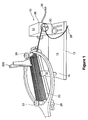
- Figure 1 shows a string tensioning device indicated generally at 10 according to the present invention.
- the string tensioning device 10 is shown in association with a racquet stringing machine 12.
- the racquet stringing machine 12 includes a base 14, a racquet supporting post 16 at one end, and a string tensioning device 10 at the other end.
- the racquet stringing post 16 includes a rotatable cap element 18 having a generally horizontal support member 20 with clamp elements 22 and 24 located at opposite ends of the horizontal member 20. These elements are conventional and will be familiar to those skilled in the art.
- FIG. 1 Also shown in Figure 1 is a sports racquet 26 which is being strung with string 28.
- the sports racquet 26 is a tennis racquet, but it will be appreciated that the present invention is applicable to stringing machines that may be used with a wide variety of sports racquets including tennis, badminton, racquet ball, squash and other stringed sports racquets.
- the string tensioning device 10 is mounted to the base 14 by means of conventional bolts, welding, or the like.
- an electrical cord 32 Extending from one end of the string tensioning device 10 is an electrical cord 32 which ends in a plug head (not shown).
- the electrical cord 32 provides a connection to a standard AC power source, such as a household electrical current.
- the string tensioning device 10 also includes an outer housing 36 within which is contained a stallable electrical motor 38.
- the stallable electrical motor 38 provides torque to an output shaft 40 upon which sits a split winch element 42 which is described in more detail below and shown in Figure 7.
- stallable electric motor 38 good results have been achieved with a shaded pole alternating current motor with impedance protection.
- a shaded pole alternating current motor with impedance protection is available from Multi Products of Racine, Wisconsin and has the benefit that it may stall for extended periods of time without overheating.
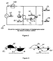
- the control circuit 50 is preferably in the form of an alternating current phase control circuit consisting of a total of five simple electronic components.
- a variable resistor 52 a fixed resistor 54, a first capacitor 56, a second capacitor 58 and a quadrac 60.
- the AC input 62 a switch 64 and the stallable electric motor 38.
- this control circuit 50 is one form of circuit to control the stall torque of the shaded pole motor of the preferred form of the invention.
- the torque control is provided by means of phase control as set out in more detail below.
- variable resistor 52 is connected in series with a first capacitor 56.
- the variable resistor 52 most preferably has a range of 0 to 100 k Ohms.
- the first capacitor 56 is most preferably of 0.068 MF.
- the second or fixed resistor 54 which is connected in series to a second capacitor 58.
- the second resistor is most preferably a 1500 Ohm resistor, with the second capacitor being again a 0.068 MF capacitor.
- the fixed resistor and second capacitor are connected in parallel to the variable resistor 52 and first capacitor 56.
- a transistor triac 70 the main terminals of which are connected in parallel to the variable resistor/first capacitor.
- a gate terminal 72 on the triac 70 is connected to one main terminal of a transistor diac 74.
- the transistor diac 74 has one main terminal 75 connected to the gate terminal 72, and the other main terminal 76 connected to the variable resistor 52, with the connection of the terminal 76 being at a point in the circuit 50 between the variable resistor 52 and the first capacitor 56.
- the variable resistor 52 connected in series to the first capacitor 56 and the fixed resistor 54 connected in series to the second capacitor 58 are so arranged in the circuit 50 such that a direct connection not passing through any other circuit elements exists between said first and second capacitors 56, 58, and so arranged that a direct connection not passing through any other circuit elements exists between said variable resistor 52 and said fixed resistor 54.
- phase control circuit 50 is connected to the AC motor 38, such that the AC motor 38 is connected in series with the variable resistor 52 connected in series to the first capacitor 56, in series with the main terminals of the triac 70 and in series with the fixed resistor 54 connected in series to the second capacitor 58.
- variable resistor 52 can be used to adjust the amplitude of the voltage at which the transistor diac 74 will trigger the transistor triac 70.
- the adjustment of the amplitude at which the transistor triac 70 is triggered controls the current passing through the circuit and therefore controls the power output of the AC motor 38, and the output torque.
- the power output for the AC Motor 38 is shown at two different settings for the variable resistor 52.
- the darkly shaded area 80 represents the motor "on” condition
- the lightly shaded area 82 is the motor "off” condition.
- This figure illustrates an example of a motor being turned on 75% of the time (i.e. at 75% of maximum torque).
- the opposite is true, with the motor being turned on only 25% of the time and generating only 25% of maximum torque.
- variable resistor 52 will be provided with a manually actuable knob 100, as shown in Figure 5, which is associated with a reference scale 102.
- reference scale 102 will provide a range of weights, which comprehend typical preferred string tension weights, such as in the range of 10 to 90 lbs., and more preferably 30 to 80 lbs. tension for tennis racquets.
- a desired reading such when 60 lbs. on the reference scale 102 is beneath a mark or pointer 104 on the knob 100.
- Appropriate gradations 106 are preferably provided on the reference scale 102 such that if another tension was required for the next racquet being strung, all that is required is to move the pointer 104 relative to the scale 102 to a new tension, for example 65 lbs.
- the reference scale 102 would be calibrated by, for example, inserting a pull scale onto the device, subjecting it to a specific amount of pull, and making the reference scale 102 reflect the tension recorded by the pull scales.
- the device settings can be changed to select a predetermined desired tension by moving the pointer 104 relative to the scale 102.
- it will be necessary periodically to re-calibrate the device 10 by tensioning a standard pull scale, selling it to a desired force, and aligning the calibration scale to the pointer on the selling knob as outlined above.
- the present device once calibrated, can be used in association with racquet stringing machine as shown in Figures 1 to 6.
- the racquet is clamped in position in the frame as indicated in Figure 1.
- a string 28 is threaded through the holes in the racquet in accordance with the racquet manufacturer's stringing specifications.
- the free end of the string is extended is extended outwardly from the racquet frame and is wrapped around the gripper 42 which is on the output shaft of the string tensioning device 10.
- the preferred form of gripper element 42 is in the form of a moulded or cast split winch element which is rigidly secured to the output shaft 40 of the device 10.
- a close up of one form of the moulded element 42 is shown in Figure 4 and includes the string 120, a movable winch element 122 and a fixed winch element 124.
- the fixed winch element is held by a fastener (not shown) axially threaded in the center of the motor shaft 40, said motor shaft containing a pin (not shown) transversally mounted in the motor shaft so as to fit in a keyway (not shown) moulded in the fixed winch element 124.
- the movable winch element 122 is movably mounted by means of fastener 128 which locates movable winch element 122 in relation to fixed winch element 124.
- Fastener 128 rides in slot 129 allowing the movement of movable winch element 122 transversally in relation to the line at which winch elements 122 and 124 separate.
- the string 120 loops around the two winch elements 122, 124 and then is hooped between the winch elements 122, 124 with a free end at 130.
- Tension on the string 120 in the direction of arrow T causes the winch elements to compress together further gripping the string 120.
- the more tension that is applied the more firmly the string 120 is gripped by the gripping element 122, 124.
- the gripping element is formed from moulded polyurethane which is a soft but durable material which does not mar or otherwise nick the string.
- the moulded polyurethane is most preferably a composite which includes a friction increasing agent such as coarse sand or silica. This form of friction increasing agent is gentle and prevents the string from acquiring nicks or the like and yet is effective at increasing the friction between the string and the winch elements.
- FIG. 6 a further embodiment of the gripping element 42 is shown at 42'.
- all of the elements are the same, except that either of the fixed winch element 124' or the movable winch element 122' are provided with a key 180, and the other is provided with a keyway 182, into which key 180 fits. Sharp corners, which could otherwise nick the string are to be avoided, but the key/keyway combination has the result of more securely gripping the string between the elements 122' and 124'.
- a rounded rectangular key/keyway is shown it will be appreciated by those skilled in the art that many different profiles are possible, which would achieve the same results. It will be appreciated by those skilled in the art that the use of a friction inducing agent and/or a friction inducing geometry in the keyway will enhance the gripping properties of this winch arrangement considerably.
- gear box 150 Located between the stallable motor and the output shaft is most preferably a gear box 150.
- the gear box is of a conventional type and simply changes the speed and torque characteristics of the stallable motor to the desired torque range for stringing a racquet such as a tennis racquet. Such a gear box is well known in the art and is therefore not discussed in any further detail herein.
- the present device can be used in association with a stringing machine to string a racquet once the device has been appropriately calibrated.
- the first step is to clamp the racquet in the racquet clamping frame as shown in Figure 1.
- the string is weaved through the racquet in the manner taught by the manufacturer of the racquet. This results in the free end extending from the racquet frame which needs to be tensioned.
- the string is simply wound around and fed between the gripping elements and the motor is then engaged.
- the preselected tension is set by moving the pointer on the calibration scale to the desired predetermined tension.
- the motor will then advance the gripping element in a circular fashion until the desired torque is achieved at which point the motor will stall.
- the operator will easily recognize the stall condition because the winch element is no longer revolving. Then, the operator may use a conventional flying clamp 200, as illustrated in Figure 1 to clamp the string to maintain tension in the string to maintain tension in the string during the next phase of the stringing operation.
- the motor can be disengaged by tripping switch 64.
- an indicator light may be provided on the face of the device. The indicator light simply indicates whether the motor is on or off. Also, it is desirable to provide an easily accessible switch 64 for the purpose of energizing and de-energizing the motor.
- the string simply unwinds from the winch element when not being tensioned by the motor.
- the free end can be easily removed from the gripping element and threaded back through the racquet frame in the manner specified by the racquet manufacturer.
- the free end can be simply and quickly wrapped around the gripping element, the motor engaged and the next section of the racquet string tensioned across the frame.
Landscapes
- Health & Medical Sciences (AREA)
- General Health & Medical Sciences (AREA)
- Physical Education & Sports Medicine (AREA)
- Tension Adjustment In Filamentary Materials (AREA)
- Basic Packing Technique (AREA)
- Control Of Electric Motors In General (AREA)
Applications Claiming Priority (2)
| Application Number | Priority Date | Filing Date | Title |
|---|---|---|---|
| US299081 | 1999-04-26 | ||
| US09/299,081 US6162139A (en) | 1999-04-26 | 1999-04-26 | String tensioning device |
Publications (2)
| Publication Number | Publication Date |
|---|---|
| EP1048328A2 true EP1048328A2 (fr) | 2000-11-02 |
| EP1048328A3 EP1048328A3 (fr) | 2003-12-10 |
Family
ID=23153227
Family Applications (1)
| Application Number | Title | Priority Date | Filing Date |
|---|---|---|---|
| EP00303513A Withdrawn EP1048328A3 (fr) | 1999-04-26 | 2000-04-26 | Dispositif de mise sous tension d'une corde |
Country Status (2)
| Country | Link |
|---|---|
| US (1) | US6162139A (fr) |
| EP (1) | EP1048328A3 (fr) |
Cited By (1)
| Publication number | Priority date | Publication date | Assignee | Title |
|---|---|---|---|---|
| US8066593B2 (en) * | 2007-04-11 | 2011-11-29 | Wilson Sporting Goods Co. | Customized racquet stringing system and method |
Families Citing this family (13)
| Publication number | Priority date | Publication date | Assignee | Title |
|---|---|---|---|---|
| KR200194486Y1 (ko) * | 2000-03-10 | 2000-09-01 | 유민선 | 라켓용 스트링 머신 |
| TW494782U (en) * | 2001-08-03 | 2002-07-11 | Elding Ind Co Ltd | Control device for racket threading machine |
| TW493457U (en) * | 2001-08-10 | 2002-07-01 | Ding-Wei Ju | Device for pulling thread for racket |
| US7153226B1 (en) * | 2005-12-27 | 2006-12-26 | Erik Bernard Van Der Pols | String-pulling device of a racket stringing apparatus |
| USD571384S1 (en) * | 2007-01-23 | 2008-06-17 | Erik Bernard Van Der Pols | String-pulling body of a racket stringing apparatus |
| US7833118B2 (en) * | 2007-04-11 | 2010-11-16 | Wilson Sporting Goods Co. | Racquet stringing machine |
| US7695383B2 (en) * | 2007-04-11 | 2010-04-13 | Wilson Sporting Goods Co. | Racquet stringing machine |
| US7686713B2 (en) * | 2007-04-11 | 2010-03-30 | Wilson Sporting Goods Co. | Racquet stringing machine |
| US8075429B2 (en) | 2007-04-11 | 2011-12-13 | Wilson Sporting Goods Co. | Racquet stringing machine |
| US8206249B1 (en) * | 2011-04-08 | 2012-06-26 | Herbert H. Wise | Electronic racquet stringing machine |
| CN104771877B (zh) * | 2015-04-02 | 2017-05-24 | 厦门德欧赛特环保科技有限公司 | 球拍自动穿线机 |
| US10456633B1 (en) * | 2018-06-28 | 2019-10-29 | Matthew James Polson | Systems and methods for stringing a racket |
| US11058927B2 (en) * | 2019-07-08 | 2021-07-13 | Adaptive Integrations Technology, Inc. | Automatic string weaving system for stringed sports racquet and method |
Citations (5)
| Publication number | Priority date | Publication date | Assignee | Title |
|---|---|---|---|---|
| US3302920A (en) | 1964-09-25 | 1967-02-07 | Caterpillar Tractor Co | Apparatus for producing templates |
| US3918713A (en) | 1974-03-15 | 1975-11-11 | Bernard Kaminstein | Racket stringing machine |
| EP0476982A2 (fr) | 1990-09-17 | 1992-03-25 | Vlt Corporation | Appareil électrique comprenant un convertisseur de puissance |
| US5269515A (en) | 1993-04-29 | 1993-12-14 | Chu David T | Machine for stringing game racket |
| US5733212A (en) | 1996-10-08 | 1998-03-31 | Wise U. S. A., Inc. | Electronic racket stringing machine |
Family Cites Families (13)
| Publication number | Priority date | Publication date | Assignee | Title |
|---|---|---|---|---|
| US3302950A (en) * | 1965-12-07 | 1967-02-07 | Wesley J Hartman | Racket stringing machine |
| US3635080A (en) * | 1968-05-31 | 1972-01-18 | Court & Slope Inc | Racket-stringing machine with automatic locking |
| US3913912A (en) * | 1974-04-25 | 1975-10-21 | Garcia Corp | Racket stringing apparatus |
| FR2327803A1 (fr) * | 1975-10-13 | 1977-05-13 | Babolat Maillot Witt | Machine a corder les raquettes a reglage electronique |
| US4156525A (en) * | 1977-10-03 | 1979-05-29 | Parnell Paul E | Racket stringing apparatus |
| FR2475908A2 (fr) * | 1980-02-18 | 1981-08-21 | Montana Sport | Perfectionnements a la machine a corder les raquettes |
| US4373721A (en) * | 1981-02-27 | 1983-02-15 | Ray Lynn L | Racket stringer tensioner |
| US4417729A (en) * | 1982-02-26 | 1983-11-29 | Prince Manufacturing, Inc. | Racket stringing apparatus |
| JPS60199475A (ja) * | 1984-03-26 | 1985-10-08 | 土田 明 | テニスラケツト等のガツト張り機におけるガツト引張装置 |
| US4706955A (en) * | 1986-05-20 | 1987-11-17 | Sumiaty Ngadi | Racket frame clamp for stringing machine |
| FR2642655B1 (fr) * | 1989-02-07 | 1993-02-19 | Babolat Vs | Appareil pour le cordage d'une raquette de tennis |
| US5327790A (en) * | 1992-06-19 | 1994-07-12 | Massachusetts Institute Of Technology | Reaction sensing torque actuator |
| US5820500A (en) * | 1994-05-03 | 1998-10-13 | Raos; Davor | Non-rotating racquet and stringing machine and method |
-
1999
- 1999-04-26 US US09/299,081 patent/US6162139A/en not_active Expired - Fee Related
-
2000
- 2000-04-26 EP EP00303513A patent/EP1048328A3/fr not_active Withdrawn
Patent Citations (5)
| Publication number | Priority date | Publication date | Assignee | Title |
|---|---|---|---|---|
| US3302920A (en) | 1964-09-25 | 1967-02-07 | Caterpillar Tractor Co | Apparatus for producing templates |
| US3918713A (en) | 1974-03-15 | 1975-11-11 | Bernard Kaminstein | Racket stringing machine |
| EP0476982A2 (fr) | 1990-09-17 | 1992-03-25 | Vlt Corporation | Appareil électrique comprenant un convertisseur de puissance |
| US5269515A (en) | 1993-04-29 | 1993-12-14 | Chu David T | Machine for stringing game racket |
| US5733212A (en) | 1996-10-08 | 1998-03-31 | Wise U. S. A., Inc. | Electronic racket stringing machine |
Cited By (3)
| Publication number | Priority date | Publication date | Assignee | Title |
|---|---|---|---|---|
| US8066593B2 (en) * | 2007-04-11 | 2011-11-29 | Wilson Sporting Goods Co. | Customized racquet stringing system and method |
| US20120277039A1 (en) * | 2007-04-11 | 2012-11-01 | Wilson Sporting Goods Co. | Customized racquet stringing system |
| US8303441B1 (en) * | 2007-04-11 | 2012-11-06 | Wilson Sporting Goods Co. | Customized racquet stringing system |
Also Published As
| Publication number | Publication date |
|---|---|
| US6162139A (en) | 2000-12-19 |
| EP1048328A3 (fr) | 2003-12-10 |
Similar Documents
| Publication | Publication Date | Title |
|---|---|---|
| EP1048328A2 (fr) | Dispositif de mise sous tension d'une corde | |
| US9700753B1 (en) | Personal force resistance cable exercise device, force resistance assembly, and method of exercising | |
| US6712723B2 (en) | Tennis racket stringing machine | |
| KR101375810B1 (ko) | 운동 장치 및 이에 사용되는 부하 제어 장치 | |
| US6227990B1 (en) | Electronic racket stringing machine | |
| JPH02953B2 (fr) | ||
| US5139206A (en) | Wire prefeeder | |
| US20140315668A1 (en) | Racket Stringing Machine | |
| KR200490207Y1 (ko) | 낚싯줄 감는 기구 | |
| US4516739A (en) | Magnetically controlled wire tensioning device | |
| EP0873956B1 (fr) | Dispositif de tension avec contrôle automatique de la tension pour tissu | |
| US7226397B1 (en) | Rowing exercise machine | |
| US10329116B2 (en) | Sensing apparatus for yarn feeder | |
| EP0697990A1 (fr) | Cantre | |
| EP0223226B1 (fr) | Dispositif de mise en écheveaux de fils | |
| EP0295223B1 (fr) | Porte enroulable | |
| FR2327803A1 (fr) | Machine a corder les raquettes a reglage electronique | |
| US5064129A (en) | Apparatus for winding two-face adhesive tape on a club shaft of a golf club | |
| JPH0229086Y2 (fr) | ||
| CZ4994U1 (cs) | Stroj na vyplétání tenisových raket | |
| CZ166896A3 (cs) | Stroj na vyplétání tenisových raket | |
| US3275264A (en) | Wire unreeling and tensioning device | |
| WO2007138541A2 (fr) | Appareil de cordage de raquettes | |
| CN222888681U (zh) | 一种运动鞋的自动系紧机构 | |
| JPH04913B2 (fr) |
Legal Events
| Date | Code | Title | Description |
|---|---|---|---|
| PUAI | Public reference made under article 153(3) epc to a published international application that has entered the european phase |
Free format text: ORIGINAL CODE: 0009012 |
|
| AK | Designated contracting states |
Kind code of ref document: A2 Designated state(s): AT BE CH CY DE DK ES FI FR GB GR IE IT LI LU MC NL PT SE |
|
| AX | Request for extension of the european patent |
Free format text: AL;LT;LV;MK;RO;SI |
|
| RIN1 | Information on inventor provided before grant (corrected) |
Inventor name: BASSILI, JOHN |
|
| PUAL | Search report despatched |
Free format text: ORIGINAL CODE: 0009013 |
|
| AK | Designated contracting states |
Kind code of ref document: A3 Designated state(s): AT BE CH CY DE DK ES FI FR GB GR IE IT LI LU MC NL PT SE |
|
| AX | Request for extension of the european patent |
Extension state: AL LT LV MK RO SI |
|
| AKX | Designation fees paid |
Designated state(s): AT BE CH CY DE DK ES FI FR GB GR IE IT LI LU MC NL PT SE |
|
| STAA | Information on the status of an ep patent application or granted ep patent |
Free format text: STATUS: THE APPLICATION IS DEEMED TO BE WITHDRAWN |
|
| 18D | Application deemed to be withdrawn |
Effective date: 20040612 |